The Vision Miner 22IDEX V4 uses three bed fixing screws that pass through the bed and thread into the bed holders, secured from the bottom with a nut. This article explains what these screws do, where they are, and how to check them after receiving the printer.
¶ How the Bed Mount Works
The build plate sits on three support points arranged in a triangle — two at the front (left and right corners) and one at the rear (center). At each point, a steel ball is attached to the underside of the bed. Each ball rests in a holder with two guide rails, allowing the ball to slide along a fixed path.
Steel ball attached to the underside of the bed. Each of the three support points has one ball.
Bed holder with two guide rails. The steel ball sits between the rails and can slide along the fixed path.
This is a kinematic coupling — the bed is not rigidly attached to the holders. Because the bed heats to very high temperatures, it must be free to expand in all directions. If the bed were clamped down tightly, thermal expansion would cause it to warp or bow. By allowing free movement, the bed stays flat across its entire surface at any temperature.
Each bed fixing screw passes through a hole in the bed, threads into the bed holder, and is secured from the bottom with a nut. The screws prevent the bed from falling off the holders, but they must not clamp the bed down. The bed should have 2–3 mm of upward play at each of the three screw locations. This play is essential — it lets the bed expand freely when heated and tilt during automatic bed leveling.
NOTE: The screws can be removed entirely, but this is not recommended during normal operation — if an emergency occurs (e.g. a crash or sudden stop), the bed could fall off the holders.
¶ Screw Locations and Specifications
Three countersunk M3 screws, one at each bed support point:
- Front left — left corner of the bed frame
- Front right — right corner of the bed frame
- Rear center — center rear of the bed frame
Overview of all three bed fixing screw locations: front left, front right, and rear center.
Close-up of an installed bed fixing screw. The countersunk M3 screw passes through the bed and threads into the holder, secured from the bottom with a nut.
Tools needed (only if adjustment is required):
- 2 mm Hex screwdriver (hex wrench)
- 5.5 mm wrench or socket
¶ Checking the Bed After Receiving the Printer
The screws are pre-configured at the factory. After receiving the printer, verify that the bed has 2–3 mm of upward play in all three corners:
- Gently lift the bed upward at each of the three screw locations (front left, front right, rear center).
- The bed should move up freely by 2–3 mm at each point.
- If the bed moves freely upward at all three corners — the screws are set correctly and the printer is ready for use.
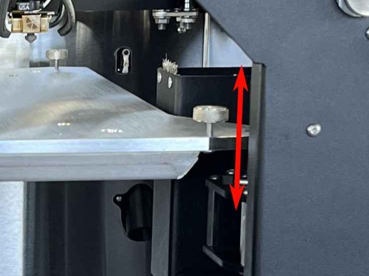
Checking bed play: gently lift the bed upward at a screw location. The bed should move up freely by 2–3 mm.
If the bed is locked and has no upward play, use a 2 mm hex screwdriver to hold the screw and a 5.5 mm wrench to loosen the nut from the bottom. Unscrew the screw a few millimeters upward until the bed has 2–3 mm of play, then re-tighten the nut to lock the screw in this new position.
¶ Rear Screw — Must Be Flush with the Bed Surface
IMPORTANT: The rear center screw must not protrude above the bed surface. If it sticks up, it will push against the build plate from below and distort the bed mesh height map, causing uneven first layers.
After checking play, verify that the rear screw head is flush with or slightly below the bed surface. If it protrudes, it can push the build plate up from below and make the surface uneven. Use a 2 mm hex screwdriver to turn it down until it is flush.
To check, slide a credit card (or similar thin, flat object) between the bed surface and the build plate at the rear screw location. If the card catches on the screw head, the screw is protruding and must be turned down. You can also place the build plate on the bed and feel for any wobble at the rear — if the plate rocks, the rear screw is likely too high.
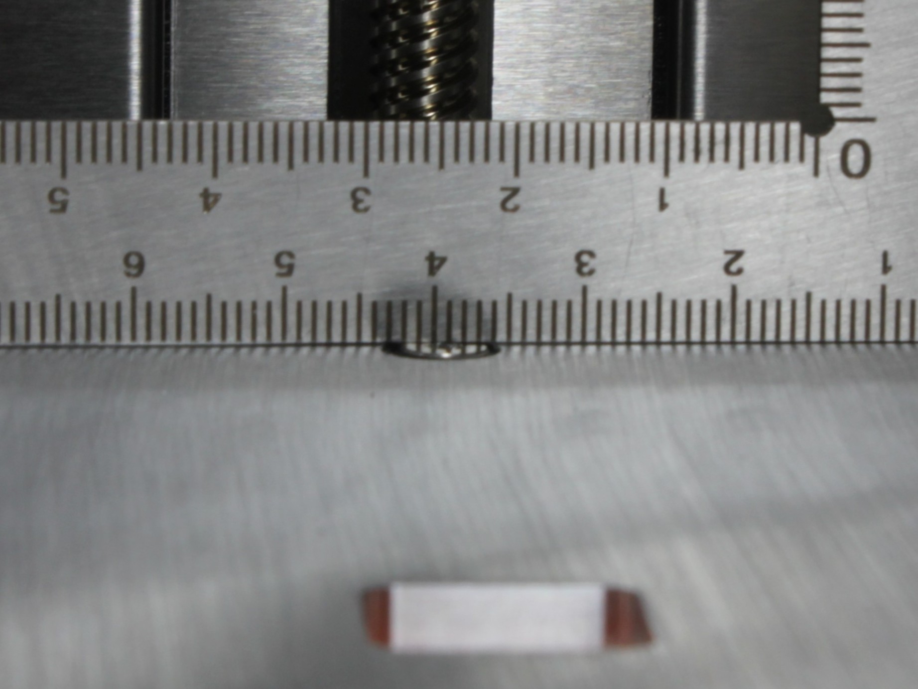
Correct: the rear screw head is flush with or slightly below the bed surface.
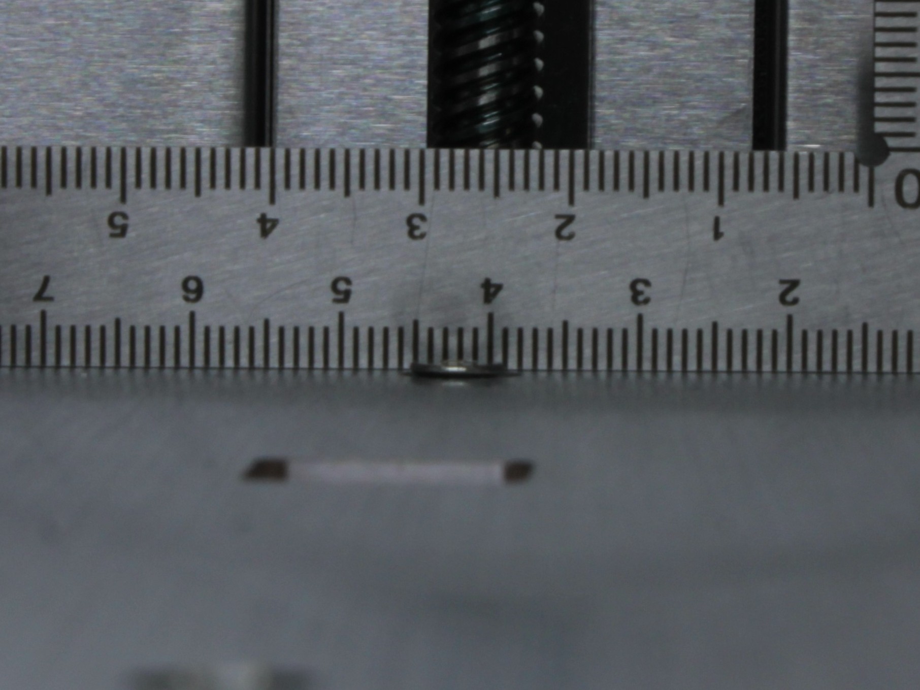
Incorrect: the rear screw protrudes above the bed surface. This will push the build plate up and distort the bed mesh height map.
¶ Transport
Before transporting the printer, verify that all three bed fixing screws are present and have the standard 2–3 mm of upward play. The screws keep the bed attached to the holders during transit. Do not tighten them beyond the normal setting.
IMPORTANT: Make sure all three bed fixing screws are installed before shipping or relocating the printer. Do not overtighten them.
After arriving at the new location, check the bed play again as described above.
¶ FAQ
¶ Do the screws affect print quality?
Not normally. As long as the bed has a few millimeters of play and the rear screw is flush with the bed surface, the screws do not affect printing or auto-calibration. If the rear screw protrudes above the bed, it can push the build plate up and distort the height map.
¶ Should I remove the screws before running auto-calibration?
No. Auto-calibration works within the normal range of play. The screws do not interfere with the leveling procedure.
¶ I'm shipping the printer — what should I do?
Make sure all three bed fixing screws are installed and have the standard 2–3 mm of upward play. The screws keep the bed on the holders during transit. Do not overtighten them. After arriving, check that the bed still has play.
¶ Do I need to measure anything when setting up?
No. Just check that the bed has 2–3 mm of upward play at all three corners. If it moves freely upward, the screws are set correctly. No measurement needed.
¶ What happens if I overtighten the bed fixing screws?
Overtightening the screws clamps the bed to the holders and prevents free thermal expansion. This can cause:
- The bed to warp or bow when heated, instead of staying flat
- Extra mechanical stress on the bed and holders
- Improper adhesion of printed parts due to an uneven surface
- Uneven temperature distribution across the bed
Always leave 2–3 mm of upward play at each screw location.
¶ Is it normal that the screws rattle?
Yes, this is completely normal. The screws are intentionally loose to allow the bed to expand freely. If the rattling bothers you, you can use the nut on the bottom of each screw to lock it in place (counter-nut). Tighten the nut against the bed holder to stop the rattle — this is exactly what the nut is there for. Make sure the bed still has 2–3 mm of upward play after adjusting.
¶ I want to try Non-Planar Printing or Demo Mode — what should I do?
Remove all three bed fixing screws before running Non-Planar Printing or Demo Mode. These modes require the bed to move freely without any screw interference.
WARNING: Running Non-Planar Printing or Demo Mode with the bed fixing screws installed will damage the printer.
After you are done, reinstall all three screws with the standard 2–3 mm of upward play.
¶ Support
Vision Miner Support
- Email: support@visionminer.com
- Phone: +1 (949) 522-4422