¶ Safety Precautions
Before you begin, please read and follow these safety guidelines:
- Power Off: Ensure the printer is turned off and unplugged from the power source.
- Hot Surfaces: Wait for all components to cool down to avoid burns.
- Sharp Edges: Be cautious of sharp edges on metal parts.
- Electrical Safety: Avoid touching electrical components.
¶ Preparation
Tools Required
- Hex 2mm Allen key
- Hex 2.5mm Allen key
- PH2 Phillips screwdriver
- Y-EndStop Tool STL
Parts Included
- 2x Y-EndStop
- 4x M3 Screws
- 4x M3 Nuts
¶ Video Guide
¶ Install the Endstops
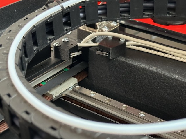
Note: Ensure the endstops are oriented correctly.
-
Position the Endstops:
- Place the endstops as shown in the image above, ensuring they are oriented correctly.
-
Secure the Endstops:
- Use the provided M3 screws and nuts to attach the endstops.
- Use the printed Y-EndStop Tool to hold the M3 nuts in place during installation.
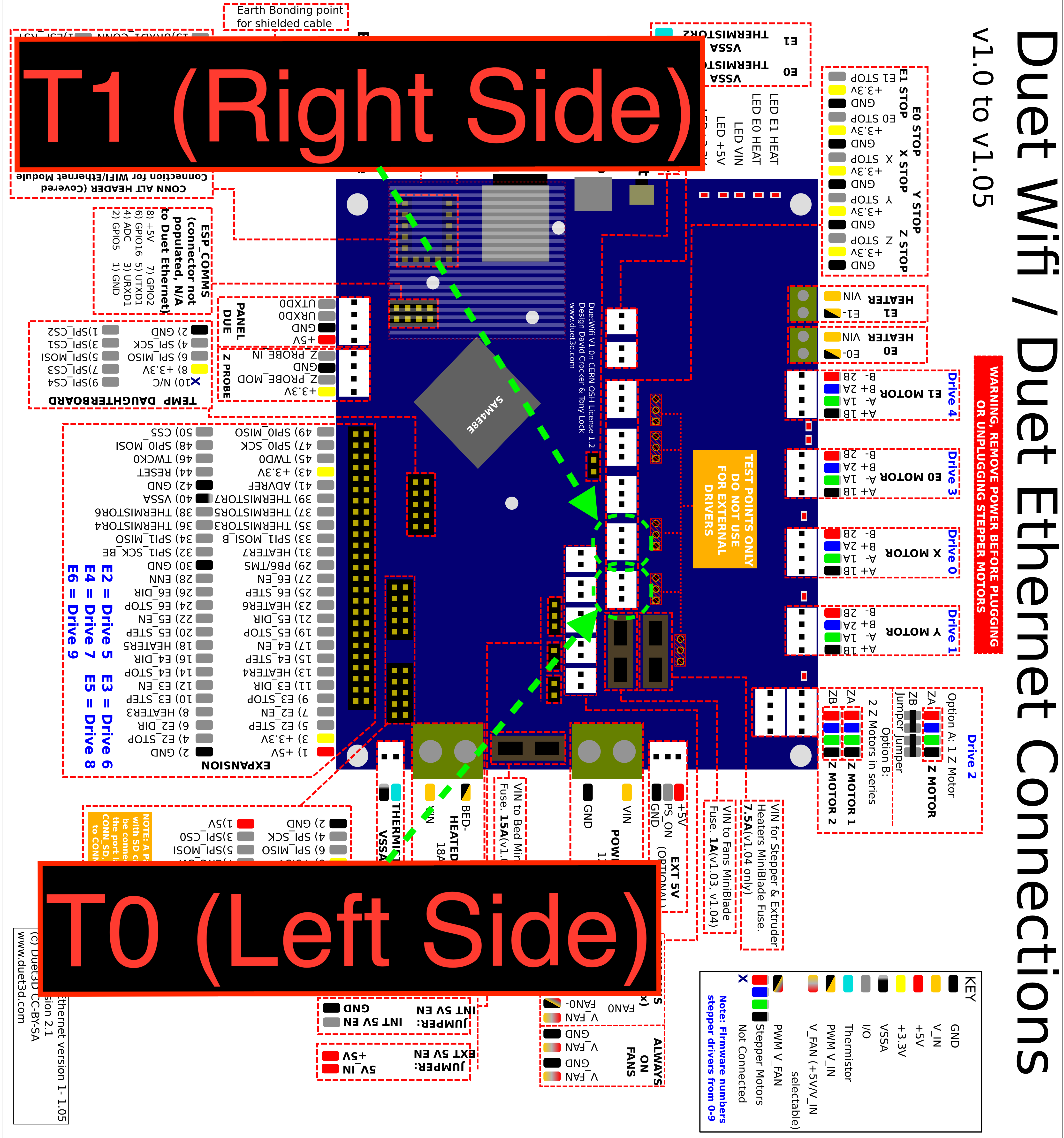
¶ Connect Wiring
¶ Move Screws (If Needed)
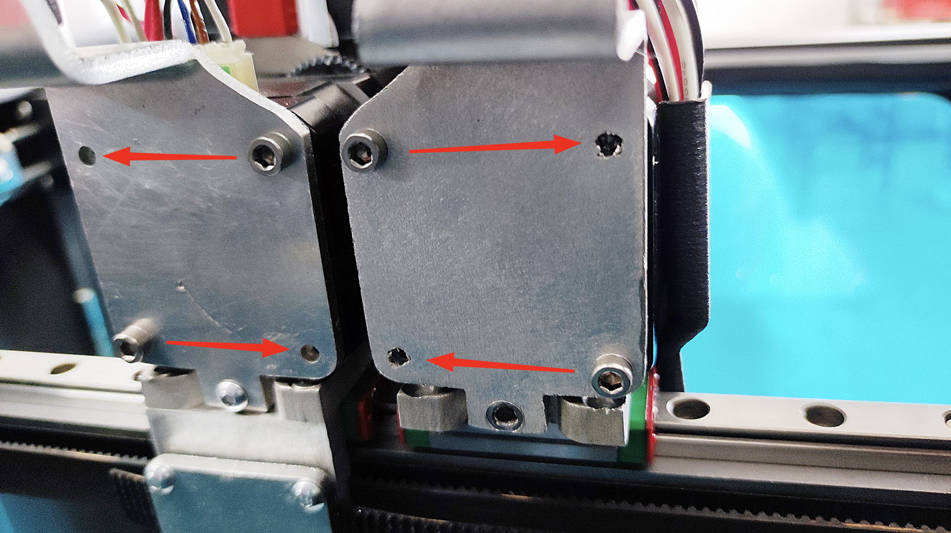
Important: The bolts on the backs of the tool heads must be positioned diagonally, with the upper screws closer to the printer's outer sides and the lower ones closer to the middle.
-
Remove the Aluminum Plate:
- Use the 2.5mm Hex Allen key to remove the two screws securing the aluminum plate on the back of the tool head.
- Use the 2mm Hex Allen key to remove the bottom screw, freeing the aluminum plate completely.
-
Relocate Extruder Screws:
- Carefully loosen one of the screws on the extruder using the PH2 Phillips screwdriver. Be cautious not to strip the screw.
- Move the loosened screw to the opposite hole diagonally (either horizontally or vertically).
- Repeat this process for the second screw, moving it to the remaining free hole.
-
Reattach the Aluminum Plate:
- Position the aluminum plate back onto the tool head.
- Lightly tighten the bottom screw using the 2mm Hex Allen key.
- Lightly tighten the two upper screws using the 2.5mm Hex Allen key.
- Finally, securely tighten all three screws on each side.
¶ Update Firmware
After installation, you must update the firmware to the latest version compatible with V2 printers equipped with Y-EndStops.
¶ Homing Process Description
After installing the endstops and updating the firmware, the homing process should proceed as follows:
-
Initial Movement:
- The crossbar moves to the front end, then slightly back, and forward again to calibrate.
-
Y-Axis Homing:
- The crossbar moves to the maximum back position.
-
X and U-Axis Homing:
- The left head moves to the far left (X-axis).
- The right head moves to the far right (U-axis).
-
Endstop Alignment Check:
- The heads move slightly away from the sides.
- The printer aligns the crossbar along the Y-axis; one side may adjust slightly forward or backward.
-
Final Calibration:
- The printer re-homes the X and U axes if necessary.
Note: The homing process should be smooth without any unusual noises or movements. If it differs significantly from this description, please record a video and contact support.
¶ Ensure No Crossbar Skew
- Error Message: If the crossbar adjustment during Y-axis homing exceeds the allowed limit, you will be notified in the web interface.
- Visual Inspection: When homing the Y-axis, observe the crossbar correction. It should not twist more than 1 mm.
¶ Troubleshooting
-
Misaligned Crossbar:
- Solution: Print and install the Adjustable EndStop Holder. Adjust it until both endstops contact the heads simultaneously with minimal crossbar skew.
-
Incorrect Endstop Orientation:
- Solution: Ensure endstops are mirrored and oriented with the open side down and metal plates facing each other.
-
Homing Process Errors:
- Solution: Verify that the firmware is updated and check endstop connections