This guide covers the auto-calibration procedure for the Vision Miner 22IDEX V4 printer. Auto-calibration establishes precise nozzle heights, Z-offset, bed mesh compensation, and XY alignment — all in one automated sequence. Run this procedure after nozzle changes, significant maintenance, or if you suspect alignment issues.
The printer heats both nozzles and probes them against the bare aluminum bed to measure their relative positions. The full calibration sequence includes:
- Tool Height Calibration — measures the height difference between Tool 0 (left) and Tool 1 (right). This offset is critical for Mirror Mode and Duplicate Mode printing. Optional — can be skipped.
- Z-Offset Calibration — sets the precise first-layer height for proper bed adhesion.
- Mesh Bed Calibration — probes the bed surface to create a compensation map for surface variations. Provides additional first-layer accuracy when enabled in printer settings (if enabled).
- XY Auto Squaring — corrects axis perpendicularity in the XY plane (if enabled).
- Steps per mm Calibration — calibrates motor steps per millimeter for dimensional accuracy (if enabled).
- XYZ Offset Calibration — measures the offset between nozzles using the square cutout in the build plate. Essential for multi-color and multi-material printing.
¶ Safety and Warnings
Attention: Remove the build plate before starting. The nozzles must directly contact the bare aluminum bed. Running calibration with the build plate installed will damage the machine.
WARNING: The nozzles will be heated to working temperature during this procedure. Do not touch the hotends, heater blocks, or nozzles without heat-resistant gloves.
WARNING: When cleaning nozzles with a wire brush, keep the brush away from the heater cartridge wires and temperature sensor wires. A short circuit can blow a fuse or damage the mainboard.
IMPORTANT: During nozzle probing, the machine may briefly display a red error box: "Error: Probe was not triggered." This is part of the normal probing sequence — not an actual error. The probing process works by approaching incrementally, and this message appears during initial approach. We know this is not optimal and are working on improving it.
¶ Tools and Materials
- 2 mm hex screwdriver (hex wrench) — for heat break set screw adjustment
- 2.5 mm hex screwdriver (optional) — for leveling the heater block during adjustment
- Wire brush (brass recommended) — for nozzle cleaning
- Heat-resistant gloves (optional — recommended when handling hot components)
¶ 1. Starting the Calibration
- Open the Dashboard in the Web Interface.

- Open the Macros panel and select Auto Calibration.
- Enter the target temperature for the left tool (Tool 0) when prompted. Use the temperature matching the filament last loaded in that hotend. For a new machine or clean nozzles, use 250 °C.

- Enter the target temperature for the right tool (Tool 1). Same rule — match the loaded filament, or use 250 °C if clean.

- Confirm that the build plate has been removed when prompted. Click OK.

- The printer will automatically heat both nozzles, home all axes, and prepare for calibration.
¶ 2. Nozzle Cleaning
-
The printer runs an automated nozzle wipe using the built-in cleaning brushes. Wait for it to complete.
-
When prompted, manually clean both nozzle tips with a wire brush (brass preferred). Remove all plastic residue — even small traces affect probe accuracy.
WARNING: Keep the wire brush away from the heater cartridge and temperature sensor wires. A short circuit can blow a fuse or damage the mainboard.

¶ Heat Break Check
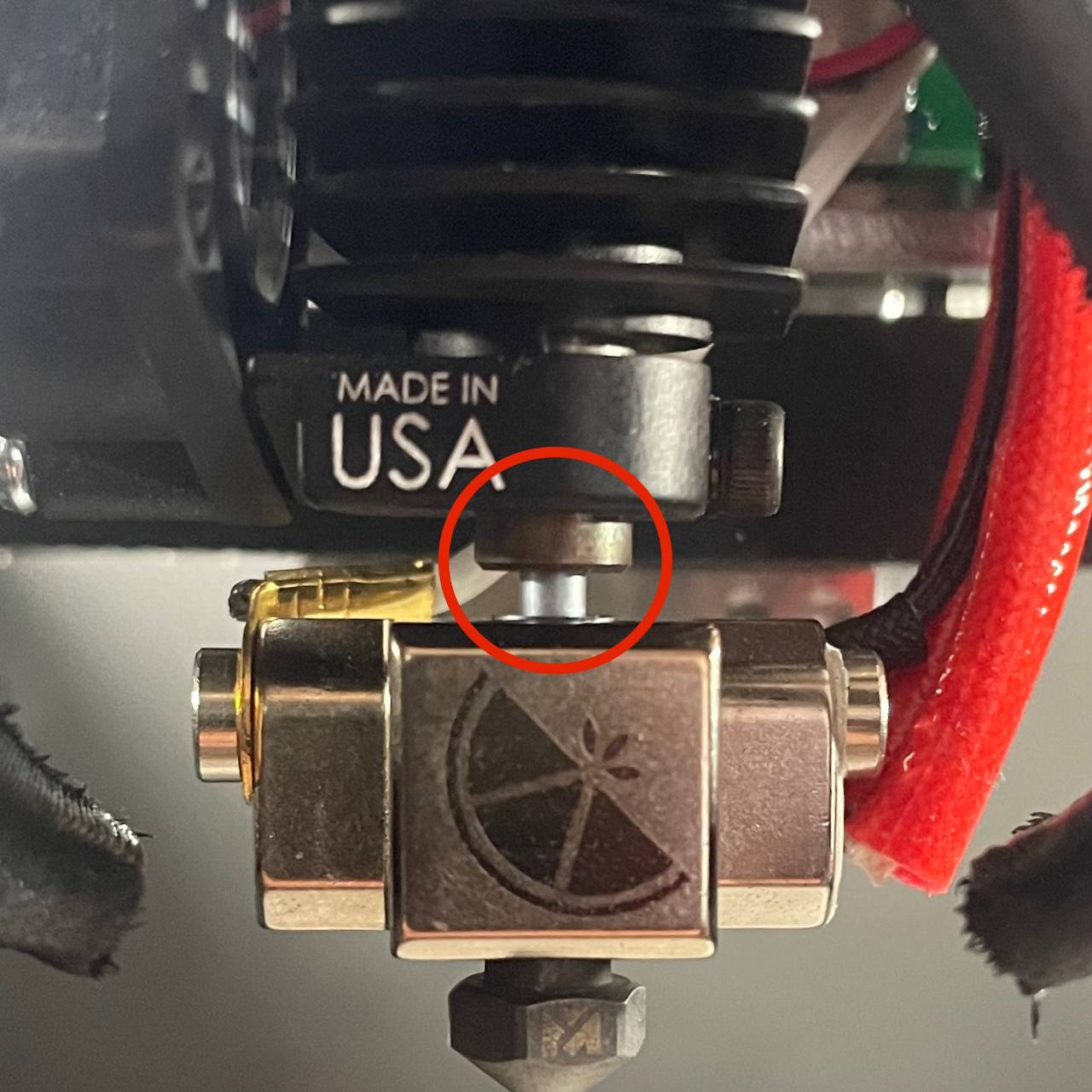
While the nozzles are accessible for cleaning, verify the position of the heat breaks on both tool heads:
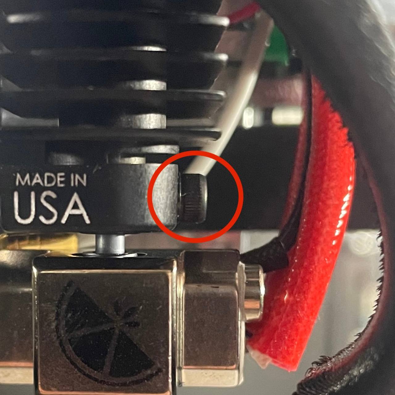
a. Check that neither heat break protrudes from the heat sink by more than 1 mm (≈ 1/32 in.).


b. If a heat break protrudes too far, locate the set screw on the side of the heat sink for that tool head.
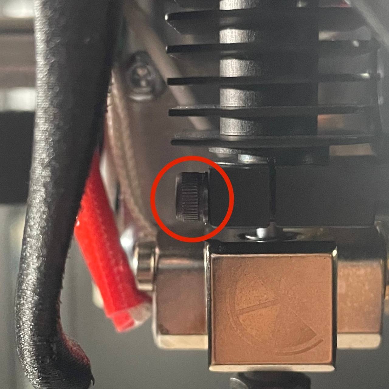
c. Use the two-screwdriver method: with a 2 mm hex screwdriver, loosen the set screw. Then use a second tool (e.g., the 2.5 mm hex wrench from the kit) to gently level the heater block and push the heat break upward until it protrudes no more than 1 mm. Retighten the set screw.
d. Complete this for both tool heads before proceeding.
-
Click OK in the Web Interface prompt once both nozzles are clean and heat breaks are verified.
-
The printer homes all axes again and begins probing.
¶ 3. Tool Height Calibration
-
The machine probes both nozzles against the bed to measure their height difference. The target is a deviation under 50 microns (0.05 mm).
-
If the deviation is within tolerance, the printer proceeds automatically to Z-Offset Calibration. Skip to Remaining Calibration Steps.
-
If the deviation exceeds 50 microns, a prompt appears with three options: Calibrate, Skip Calibration, or Cancel Calibration. Select Calibrate to adjust the heat break.

¶ 4. Adjusting the Heat Break (If Required)
WARNING: The hotend components are hot. Wear heat-resistant gloves or use tools to avoid burns.
-
The Web Interface prompt will indicate which tool (left or right) needs adjustment. Identify the corresponding nozzle.
-
Locate the set screw on the side of the heat sink that secures the heat break for the indicated tool.
-
Loosen the set screw approximately one full turn with a 2 mm hex screwdriver. Do not fully remove it — just enough so the heater block can slide up and down.
-
Use the two-screwdriver method: hold a second tool (e.g., the 2.5 mm hex wrench) against the heater block to level it and push it down approximately 2–5 mm (≈ 3/16 in.).
WARNING: The heater block is hot. Use tools — do not push with bare fingers.

-
Slightly re-tighten the set screw — just enough to prevent the hotend from wobbling, but loose enough that the bed can still push it upward during the next probing sequence. Too tight = bed can't adjust; too loose = inaccurate result.
-
Click OK in the Web Interface prompt. The printer probes the nozzle against the bed, pushing the loosened hotend upward until it matches the height of the other nozzle.
¶ Tighten the Heat Break
- Once the printer finds the correct height, it positions the nozzle for access. When prompted, permanently tighten the heat break set screw with the 2 mm hex screwdriver.

- Click OK to confirm. The machine re-runs the tool height check. If within tolerance, it proceeds automatically. If still out of tolerance, repeat steps 14–21.
¶ 5. Remaining Calibration Steps
-
After tool height calibration passes, the following steps run automatically without user interaction:
- Z-Offset Calibration — sets the first-layer height
- Mesh Bed Calibration — creates a bed compensation map (runs if enabled in printer settings)
- XY Auto Squaring — corrects axis perpendicularity (runs if enabled in printer settings)
- Steps per mm Calibration — calibrates motor steps per millimeter (runs if enabled in printer settings)
- XYZ Offset Calibration — measures nozzle offset using the square cutout in the build plate
-
When all steps complete, the printer displays a summary with calibration results:
- Tool 1 Z Offset — the height difference between Tool 0 and Tool 1. The two nozzles can never be perfectly level mechanically, but the printer compensates for this offset automatically. This is critical for dual-head printing (Multi color/Dual Material Printing) — it ensures consistent layer height and maximum bonding strength between two materials.
- Z-Offset — the distance between the nozzle tip and the bed surface. Determines how well the first layer adheres to the build plate.
- Tool 1 Y-Offset — the Y-axis positional offset between the two nozzles. Used to align toolheads in the XY plane so that multi-color and multi-material prints line up correctly.
- Tool 1 U-Offset — the U-axis (secondary X) positional offset between the two nozzles. Same purpose as Y-Offset but in the X direction.
- XY Skew — the perpendicularity correction between X and Y axes. Compensates for any mechanical skew in the crossbar (if enabled).
- Steps per mm — motor step calibration values for dimensional accuracy. Corrects any deviation in actual travel distance vs expected distance (if enabled).

- Click OK to dismiss the results. Reinstall the build plate — the printer is ready for use.
¶ Related Articles
- XY Alignment Calibration — fine-tune XY alignment between toolheads using a test print after running Auto Calibration.
- Bed Leveling Calibration — adjust bed leveling for consistent first-layer adhesion across the build surface.
¶ FAQ
¶ When should I run auto-calibration?
After nozzle changes, heat break adjustments, any maintenance on the motion system or hotends, or whenever you notice first-layer inconsistency or nozzle misalignment between tools.
¶ Can I skip the tool height adjustment if prompted?
Yes — select Skip Calibration at the prompt. The remaining calibrations will still run, but prints may show height differences between Tool 0 and Tool 1. Not recommended for Mirror Mode and Duplicate Mode prints, as these modes rely on both nozzles being at the same height.
¶ What if calibration keeps failing after repeated adjustments?
Check that nozzles are truly clean, heat breaks are fully seated, and the aluminum bed surface is free of debris or residue. Ensure the heat break is not bent — a bent heat break will cause the nozzle to probe at an angle, giving inconsistent results. If the issue persists, contact support.
¶ Do I need to recalibrate after changing filament?
No. Auto-calibration sets mechanical offsets that don't depend on filament type. However, if you swap nozzles or remove a hotend, run calibration again.
¶ Can I run calibration with filament loaded?
Yes. The printer automatically retracts filament before probing. However, make sure the nozzles are thoroughly cleaned before and during the process — any plastic residue on the nozzle tip will affect probe accuracy.
¶ How long does auto-calibration take?
A full auto-calibration typically takes 5–15 minutes, depending on which optional steps are enabled and whether the tool height adjustment requires manual intervention. If the tool height passes on the first attempt, it will be faster.
¶ What do the calibration results mean?
- Tool 1 Z Offset — the height difference between the two nozzles. The printer uses this to compensate automatically, so both nozzles print at the correct height. This is essential for Mirror and Duplicate Mode printing and for strong bonding between two materials in multi-material prints.
- Z-Offset — how close the nozzle sits to the bed on the first layer. A correct Z-Offset gives good first-layer adhesion without squishing filament too much.
- Tool 1 Y-Offset / U-Offset — the XY alignment between the two nozzles. These values ensure that when printing with two colors or materials, the layers line up precisely.
- XY Skew — corrects for any mechanical skew in the motion system. If the X and Y axes aren't perfectly perpendicular, this value compensates for it.
- Steps per mm — corrects the actual travel distance of each motor to match the expected distance. Improves dimensional accuracy of printed parts.
¶ What are the optional calibration steps?
- Mesh Bed Calibration — disabled by default. Enable it if you notice uneven first layers across different areas of the bed.
- XY Auto Squaring — disabled by default. Probes reference holes in the bed plate to measure axis perpendicularity and correct crossbar skew. Enable it if you notice dimensional inaccuracy or skew in printed parts.
- Steps per mm Calibration — disabled by default. Uses the same reference holes to measure actual travel distance and correct motor steps. Enable it if you need precise dimensional accuracy.
¶ How do I enable or disable optional calibration steps?
These settings can be configured through the printer's Web Interface in the system configuration. Contact support if you need help locating these settings.
¶ What should I do after calibration?
After auto-calibration, it is recommended to verify XY alignment with a test print, especially if you plan to do multi-color or multi-material printing. See the XY Alignment Calibration guide for instructions.
¶ Can I cancel calibration mid-process?
Yes — you can click Cancel at any user prompt during calibration. The printer will turn off all heaters and abort the process. No partial calibration values will be saved — your previous calibration settings remain unchanged.
¶ Troubleshooting
- Issue: Tool height deviation keeps exceeding tolerance after repeated adjustments.
- Cause: Tightening the heat break set screw shifts the nozzle along the Z-axis. Heat break may be damaged or bent.
- Solution: Tighten the set screw without applying linear force along the Z-axis. Use the two-screwdriver method to stabilize the heater block while tightening. If the heat break is visibly bent or worn, replace it.
- Issue: Calibration completes but first layer is too high or too low.
- Cause: Debris on the nozzle or bed surface affected the Z-Offset calibration result.
- Solution: Re-run auto-calibration with more thorough cleaning of the nozzles and bed. Ensure the bare aluminum bed is completely clean.
- Issue: Colors or materials are misaligned after calibration in multi-color prints.
- Cause: The XY Offset Calibration measured the offset correctly, but a dirty nozzle or bent heat break caused a slight measurement error.
- Solution: Run the XY Alignment Calibration test print to fine-tune the offset with live adjustment macros.
- Issue: Calibration aborts with "Probe is not connected" or "GND Wire is Shorted on T0".
- Cause: The Z-probe failed to attach or a grounding wire has a short circuit.
- Solution: This is a hardware issue. Contact support for diagnosis.
¶ Support
Vision Miner Support
- Email: support@visionminer.com
- Phone: +1 (949) 522-4422