¶ Brief Overview
This guide provides step-by-step instructions for replacing the Chamber Heater element in the Vision Miner 22IDEX printer. The Chamber Heater is responsible for maintaining the elevated ambient temperature within the build enclosure, crucial for printing certain high-temperature materials. This procedure involves working with electrical connections and requires caution.
¶ Introduction
The Chamber Heater helps create a stable, high-temperature environment inside the printer, reducing warping and improving layer adhesion for materials like ABS, PC, PEEK, and others. If the Chamber Heater fails or becomes damaged, it will need replacement to restore this functionality. This guide covers the safe removal of the old heater and installation of a new one.
Safety Note: This procedure involves disconnecting and reconnecting mains voltage wiring. It should only be attempted by users comfortable and qualified to work with electrical components. Always prioritize safety and ensure the printer is completely disconnected from power before starting.
¶ Tools & Materials
- Replacement Chamber Heater
- PH2 Phillips Screwdriver
- Flathead Screwdriver (Appropriate size for electrical terminal screws)
- 2.5 mm Hex Driver (For optional heater cover removal)
- 7 mm Wrench (For optional heater cover removal)
- Wire Cutters
- New Zip Ties (Small)
- Thermal Paste (e.g., Boron Nitride Paste)
¶ Safety & Pre-checks
DANGER - Electrical Hazard: Disconnect the printer from mains power AT THE WALL OUTLET before opening the rear electrical compartment or touching any internal wiring. Failure to do so can result in severe electrical shock or damage to the printer. VERIFY POWER IS DISCONNECTED.
Warning: Allow the printer, especially the Chamber Heater element and surrounding areas, to cool down completely to room temperature before beginning work to avoid burns.
Caution: Before disconnecting any wires, carefully note their exact positions on the terminals (Relay, Distribution Block). Taking clear photos is highly recommended. Incorrect wiring upon reassembly can lead to component damage, malfunction, or safety hazards.
- Ensure the printer has fully cooled down.
- Confirm printer is powered off and physically unplugged from the wall outlet.
- Gather all required tools and the new replacement Chamber Heater.
- Ensure adequate lighting and clear access to both the inside of the print chamber and the rear electrical compartment.
¶ Step-by-Step Instructions
¶ 1. Preparation and Safety
- VERIFY POWER OFF: Double-check that the printer is switched off AND unplugged from the mains power source.
- Cool Down: Ensure all components are at room temperature.
- Gather Tools: Assemble all necessary tools and the new Chamber Heater unit.
- Access Rear: Open or remove the rear access panel/door(s) to expose the electrical compartment containing the relay and distribution blocks.
¶ 2. Disconnecting the Old Heater
¶ 2.1 Electrical Disconnection (Rear)
- Identify Heater Wires: Locate the power cables originating from the Chamber Heater element. Trace them to where they connect inside the rear electrical compartment. They typically connect to a Solid State Relay (SSR) and a Power Distribution Block.
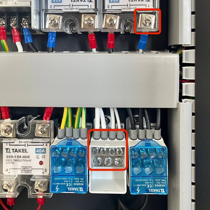
- Document Connections: (CRITICAL STEP) Take clear photos or draw a precise diagram showing exactly which terminals the Chamber Heater wires are connected to on both the Relay and the Distribution Block. Note wire colors or any polarity markings if present.
- Disconnect Wires: Using the appropriate Flathead Screwdriver, carefully loosen the terminal screws for the Chamber Heater wires on the Relay and the Distribution Block. Gently pull the wires out of the terminals.
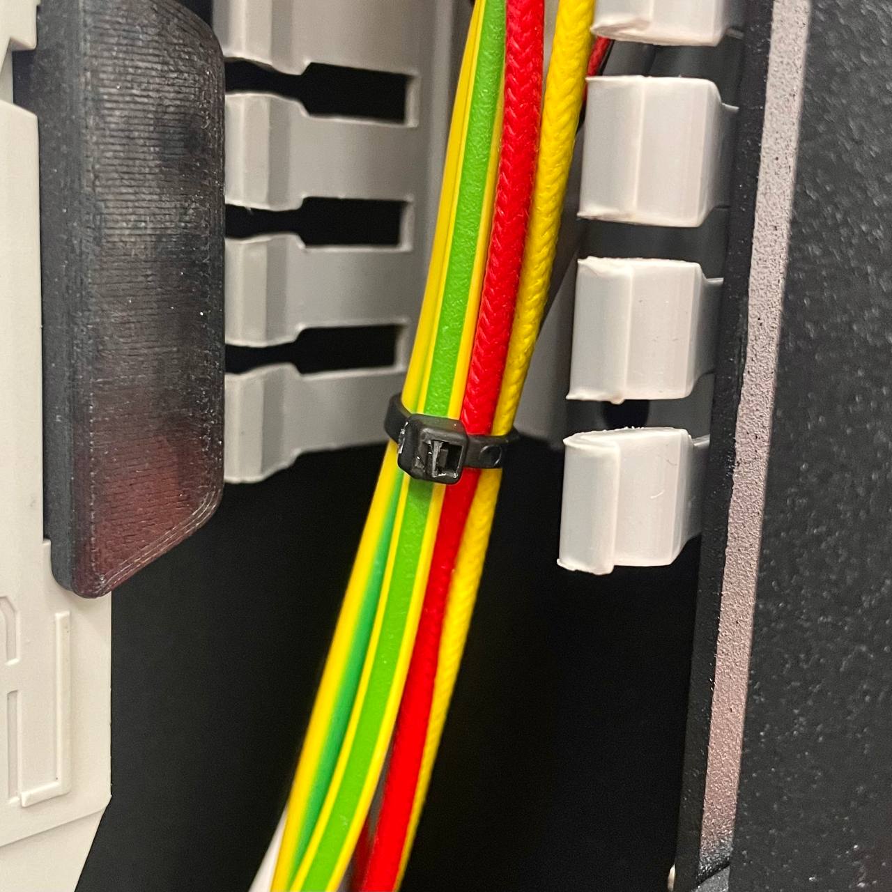
- Cut Zip Ties: Using Wire Cutters, carefully snip any zip ties that are bundling the Chamber Heater cables with other wiring within the rear compartment. Free the cables so they can be pulled through later. Be cautious not to cut adjacent wires.
¶ 2.2 Heater Removal (Inside Chamber)
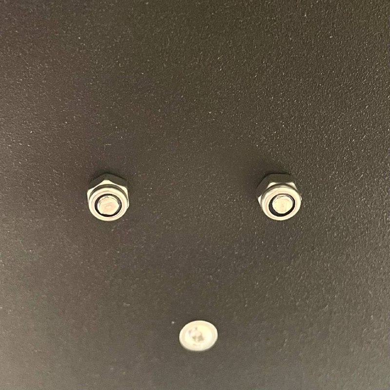
- (Optional but Recommended for Access) If the Chamber Heater has a protective metal cover, remove it now using the 2.5 mm Hex Driver and 7 mm Wrench. Keep the cover and its fasteners safely aside. (This provides better access to the heater body and sensor).
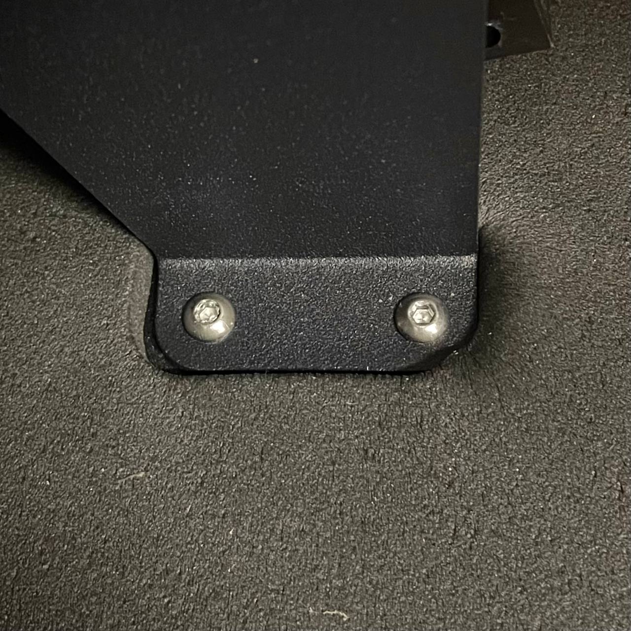
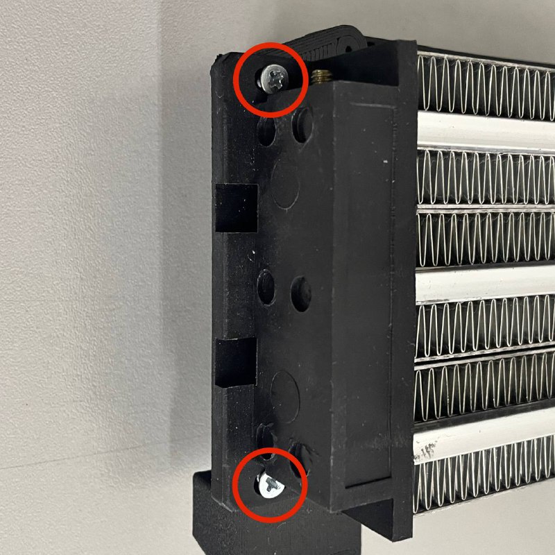
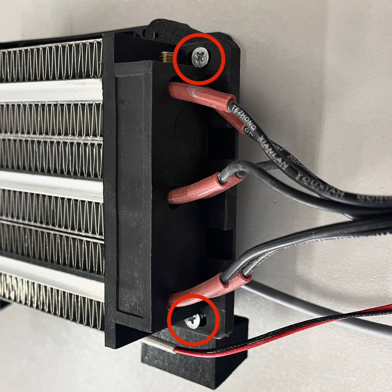
- Unscrew Heater: Using the PH2 Phillips Screwdriver, remove the screws that mount the main Chamber Heater unit to its support brackets or holders inside the print chamber.
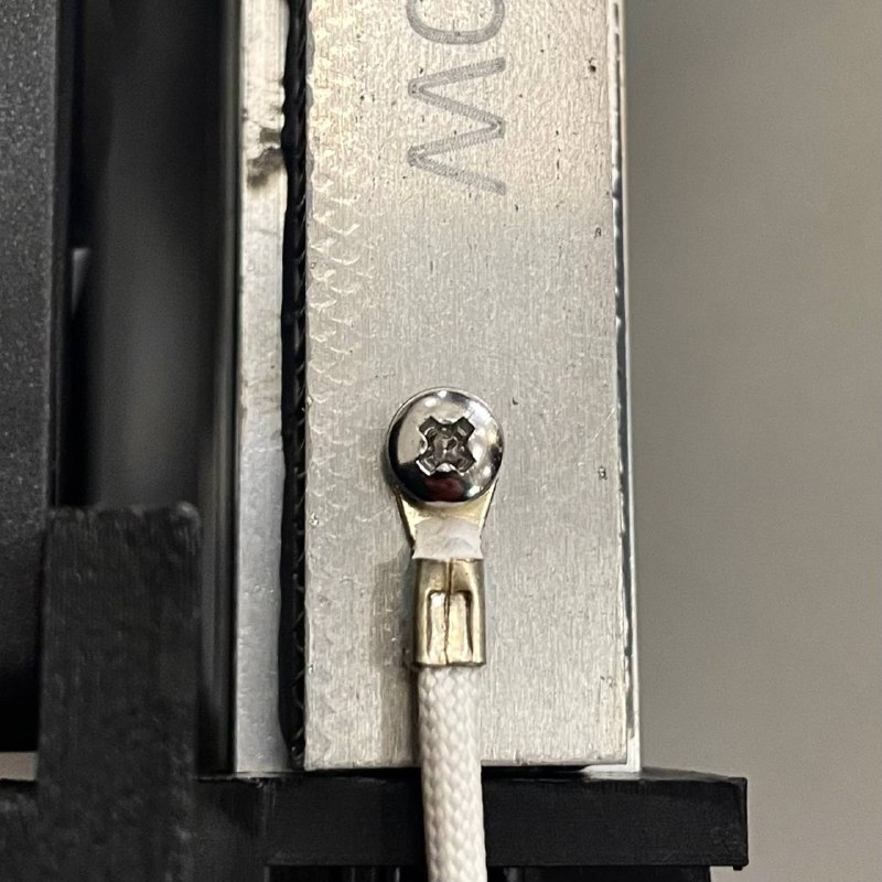
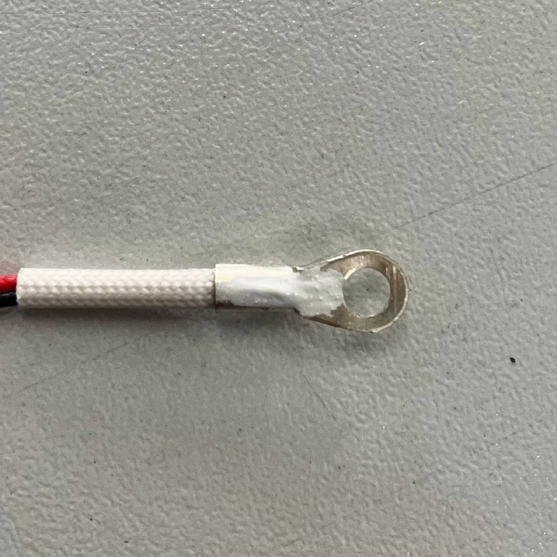
- Disconnect Temp Sensor: Locate the temperature sensor attached to the body of the Chamber Heater. Using the PH2 Phillips Screwdriver, remove the screw securing the sensor. Carefully detach the sensor from the heater body. Let it hang temporarily nearby (ensure its wire is not strained).
- Remove Heater Unit: Carefully guide the disconnected power cables (from Step 2.1) from the rear compartment into the print chamber through the frame opening. Maneuver the old Chamber Heater unit, along with its cables, out of the printer.
¶ 3. Installing the New Heater
¶ 3.1 Prepare New Heater
- Take the new Chamber Heater unit.
- Position it inside the print chamber, close to its final mounting location.
- Carefully feed the power cables attached to the new heater through the designated opening in the printer frame, pushing them from the inside of the chamber towards the rear electrical compartment. Ensure enough cable length reaches the Relay and Distribution Block area.
¶ 3.2 Install Temperature Sensor
- Retrieve the original temperature sensor you removed in Step 2.2.2.
- Apply a small bead of Thermal Paste onto the metal contact surface of the temperature sensor body.
- Carefully position the temperature sensor onto its designated mounting spot on the new Chamber Heater unit.
- Secure the sensor using its screw and the PH2 Phillips Screwdriver. Tighten until snug, ensuring good contact, but do not overtighten.
¶ 3.3 Mount New Heater (Inside Chamber)
- Align the new Chamber Heater unit with its mounting holders inside the print chamber.
- Reinstall the mounting screws using the PH2 Phillips Screwdriver, securing the heater firmly in place.
- (Optional) If you removed the protective cover, reinstall it now using the 2.5 mm Hex Driver and 7 mm Wrench.
¶ 3.4 Electrical Connection (Rear)
- Move to the rear electrical compartment. Route the new Chamber Heater power cables neatly towards the Relay and Distribution Block.
- CRITICAL WIRING: Referencing the photos or diagrams you took in Step 2.1.2, connect the new heater wires to the exact same terminals on the Relay and Distribution Block where the old heater was connected.
- Using the Flathead Screwdriver, securely tighten the terminal screws onto the wires. Gently tug each wire to confirm it is held firmly and making good electrical contact. Ensure no stray wire strands are shorting between terminals.
Warning: Double-check your wiring against your documentation. Incorrect connections are dangerous and can cause component failure. If unsure, contact support.
- Secure Cables: Use New Zip Ties to neatly bundle the new Chamber Heater cables with the surrounding wiring harness. Ensure cables are not pulled taut, pinched, or routed near sharp edges.
¶ 4. Final Checks
- Review Connections: Perform a final visual inspection of all electrical connections in the rear compartment. Ensure they match your documentation and are secure.
- Check Mountings: Confirm all screws (heater mounting, sensor, cover) are appropriately tightened.
- Cable Management: Verify cables are neatly secured with zip ties and free from potential pinching when the rear panel is closed.
- Power Up: Plug the printer power cord back into the wall outlet. Turn on the printer using the main power switch.
- Test Heating: Navigate to the printer's heating controls and select the
Extratab. Select the Chamber Heater and set it to a moderate target temperature (e.g.,50°Cor60°C).- Monitor: Observe the displayed chamber temperature on the screen. It should start rising steadily towards the target.
- Listen: Listen for the click of the Solid State Relay (SSR) engaging.
- Verify: Confirm that the heater reaches and maintains the set temperature correctly.
¶ Troubleshooting & FAQs
- Q: The chamber temperature does not increase after replacement.
- A: Power off and unplug immediately. Re-verify the electrical connections at the Relay and Distribution Block against your photos/diagrams. Ensure terminal screws are tight. Check if any printer fuses may have blown (consult printer documentation for fuse locations/ratings). Confirm the SSR is functioning (may require advanced diagnostics or support).
- Q: The displayed chamber temperature is
-200°C, or clearly incorrect.- A: Check the temperature sensor connection on the heater body (Step 3.2). Ensure the screw is snug and thermal paste was applied. Trace the sensor wire back to the mainboard and check its connection there (refer to sensor replacement guide if needed).
- Q: The printer shows a "Heating Failed" or specific Chamber Heater error.
- A: Note down the exact error message. Power off and unplug. Re-check all wiring and connections related to the Chamber Heater and its temperature sensor. Consult the printer's troubleshooting guide or contact Vision Miner support with the error details.
- Q: I saw a spark or smelled burning plastic when powering on.
- A: Power off and unplug immediately. This indicates a serious wiring error or short circuit. Do not attempt to power on again. Contact Vision Miner support for assistance.
¶ Conclusion & Additional Resources
Replacing the Chamber Heater involves careful work with electrical components. Prioritizing safety by ensuring the printer is unplugged and meticulously double-checking wiring connections is paramount. With the new heater correctly installed, your Vision Miner 22IDEX should regain its ability to maintain stable high temperatures for advanced material printing.