¶ Introduction
If you notice that your first layer is inconsistent across large prints, especially with different Z offsets on the left and right sides of the build plate, start by performing a Bed Leveling Calibration.
If problems persist after bed leveling, the issue may be related to your motion system alignment—specifically, a bow or concavity in your printer’s crossbar or misalignment of the Y-axis rails. This guide walks you through inspecting your mesh, identifying potential bowing, and adjusting your X-axis (crossbar) and Y-axis rails for optimal straightness.
¶ Tools & Materials
- Brand-new (or perfectly clean) glass build plate
- 2.5 mm Hex Screwdrivers
- 5.5 mm Wrench
- Microfiber cloth or other cleaning cloth
- Shims (for leveling corners on Y-axis if needed. For shims, you can contact our support.)
- Reference to the mesh bed visualization plugin (see the Visualizing the Mesh section)
¶ Run the Test
-
Stabilize Temperature
- Ensure your machine is at a stable (ambient) temperature.
- Make sure the build plate is not heated during this procedure.
-
Prepare the Build Plate
- Thoroughly clean the aluminum build plate to remove all residue or particles.
- Place a brand-new or perfectly clean glass build plate on top of the aluminum plate.
- Do not tighten it with thumbscrews, as external force might introduce distortion.
- We assume the glass plate is as close to perfectly flat as possible for calibration.
-
Run Mesh Bed Leveling
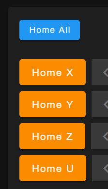
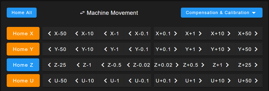
- In the printer’s web interface go to the
Dashboardtab and selectHome Allto home every axis.
- Press
Compensation & Calibrationdropdown and selectRun Mesh Compensation (G29)or enter theG29code.
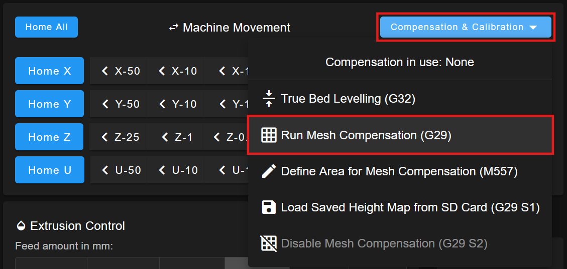
- This will probe various points on the bed and record a mesh map of height deviations.
- In the printer’s web interface go to the
¶ Visualizing the Mesh
-
Enable Mesh Bed Visualization Plugin
- In the web interface, go to
Pluginstab and enable theHeight Mapplugin.
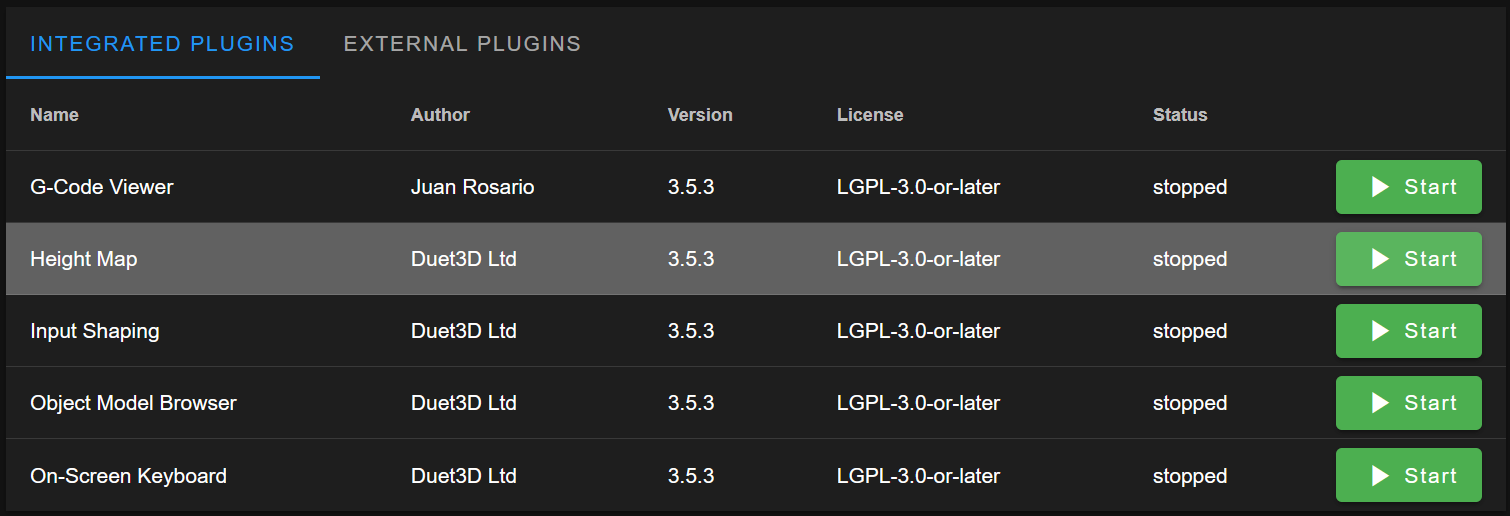
- In the web interface, go to
-
View the Mesh
- Navigate to the
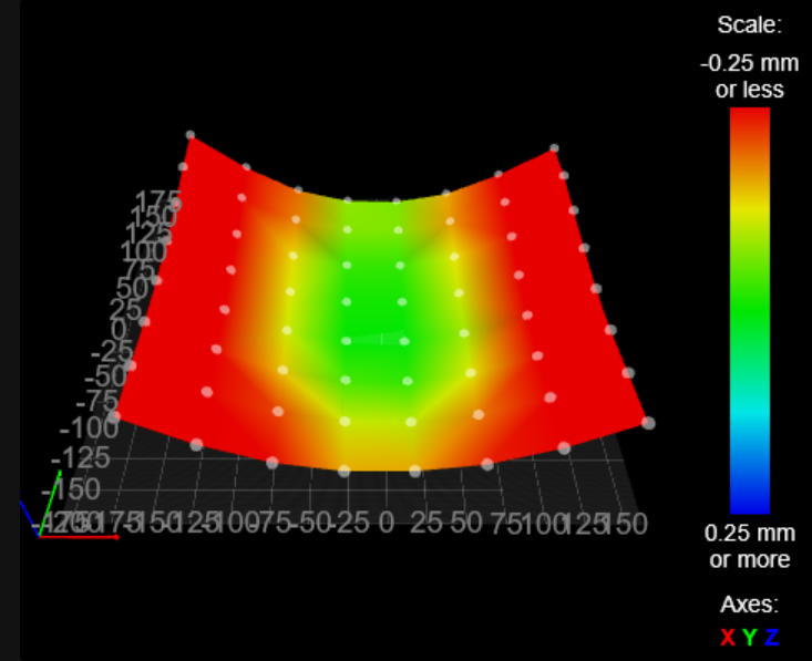
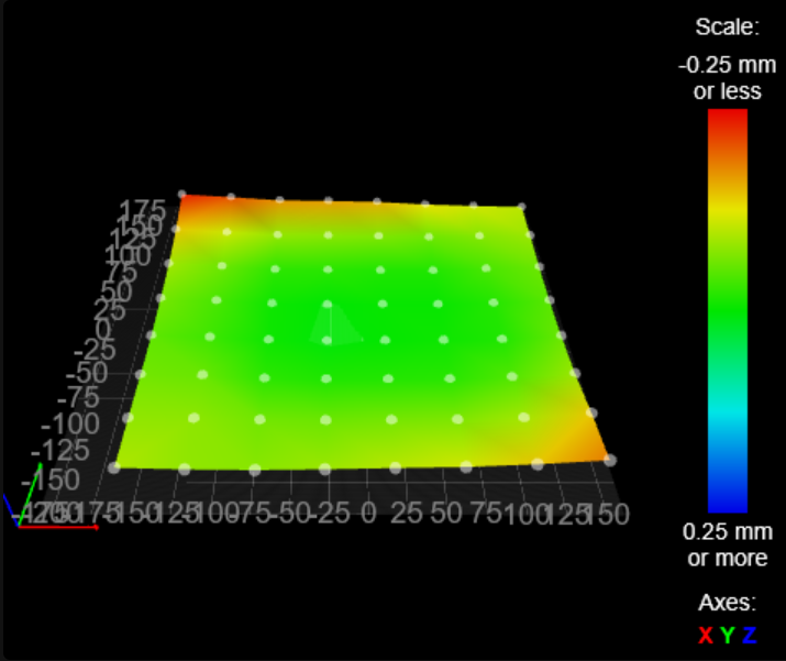
Height Maptab to see the last recorded mesh. - For easier analysis of high/low points, select
Invert Z coordinates. This shows the bed deviations in a way that correlates to how the crossbar or rails might be bowed.
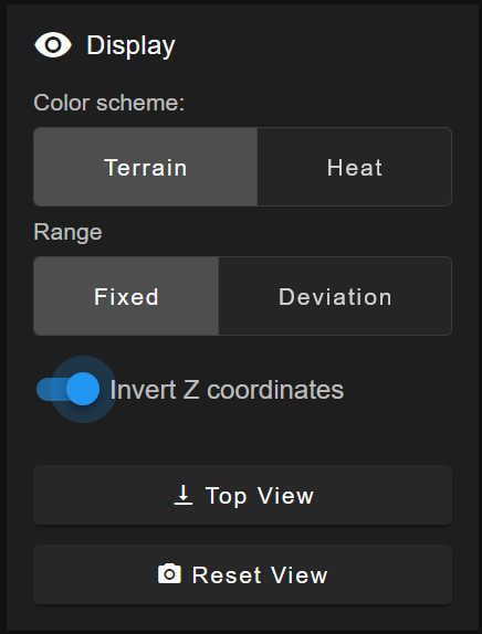
- Navigate to the
¶ Analyzing the Mesh
-
Invert Z coordinate
- Ensure
Invert Z Coordinatesis checked in the mesh visualization. This helps you see whether your crossbar is concave up or down.
- Ensure
-
Objectives
- X-axis Straightness: Look at the line formed along the X-axis in the visualization. It should appear straight (even if it’s slightly tilted, it should not bow).
- Y-axis Straightness: Check for parallelism across the front and back rails. Uneven corners or a skewed mesh may indicate that Y rails are not parallel.
If the mesh indicates bowing or curvature along the X-axis, proceed with the X-axis Straightness procedure. If the X-axis is already straight, you can skip to Adjusting the Y-Axis Parallelity.
¶ Adjusting the X-Axis Straightness
If the reading along the X-axis is bowed or concave (concave up or down), you will need to adjust the crossbar. The goal is to make the X-axis as straight as possible according to the mesh.
-
Observe the X-axis Reading
- Identify where the mesh curves. Is it concave up in the middle (like a “U” shape) or concave down (like an “n” shape)?
- Decide if you need to push the center of the crossbar up or down to flatten it.
- Identify where the mesh curves. Is it concave up in the middle (like a “U” shape) or concave down (like an “n” shape)?
-
Loosen the Linear Rail from the Crossbar
- Locate the screws that secure the linear rail to the crossbar.
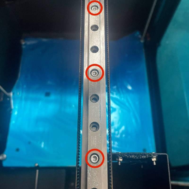
- Use a 2.5 mm hex screwdriver on the screws and a 5.5 mm wrench to hold the nuts underneath.

- Loosen each screw by about one full turn so that the linear rail can move slightly on the crossbar.
- Locate the screws that secure the linear rail to the crossbar.
-
Loosen the Y-Rail Attachment Screws
- At the top of the machine, you will see two screws on each side (front and back) that hold the Y-rails to the top gantry (via spacers).
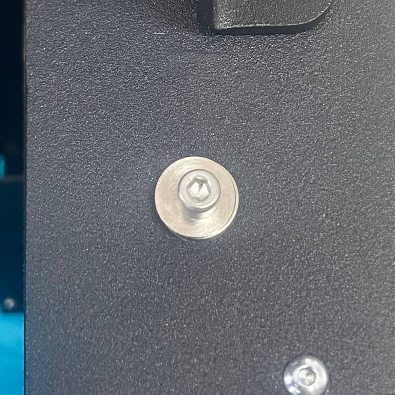
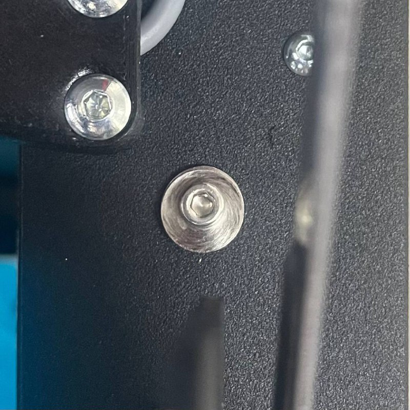
- Use a 2.5 mm hex screwdriver to loosen these screws by about half a turn to one full turn. This allows the crossbar some freedom to move.
- At the top of the machine, you will see two screws on each side (front and back) that hold the Y-rails to the top gantry (via spacers).
-
Deflect the Crossbar as Needed
- Compare the mesh to see how much the crossbar is out of alignment.
- If you have a 1 mm bow, you may need to push it up or down a few millimeters (potentially 5 mm or more) to compensate.
- Methods:
- Manual Push/Pull (with assistance):
Have a second person help push or pull the crossbar while you tighten the screws. If you need to push the center down, for instance, someone can gently apply downward pressure as you secure the screws. - Using a Screwdriver and Build Plate (for upward deflection):
- Place a screwdriver (or a similarly sturdy tool) vertically on top of the build plate, directly under the center of the crossbar.
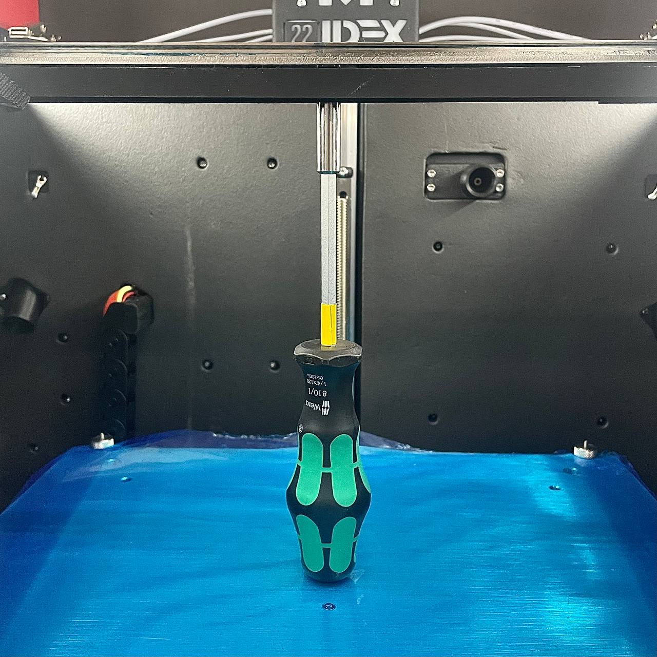
- Very carefully raise the build plate (by controlling the Z-axis movement) so that the build plate pushes the screwdriver upward, which in turn pushes the crossbar up.
- Deflect the crossbar more than the measured bow. For example, if you have a 1 mm bow, you may push it up by 3–5 mm to compensate.
- Keep the crossbar in that deflected position while tightening the screws (see Step 5).
- Place a screwdriver (or a similarly sturdy tool) vertically on top of the build plate, directly under the center of the crossbar.
- Manual Push/Pull (with assistance):
-
Tighten the Crossbar Screws
- While holding the crossbar in the deflected position, start tightening the linear rail screws.
- Begin from the center screw, then work outward left to right, alternating side to side to ensure even load distribution.
- Check that the rail does not slip while you tighten.
-
Re-secure the Top Gantry Screws
- Move the crossbar to the back of the machine and tighten the two screws on each side.
- Then move the crossbar to the front of the machine and tighten those two screws.
- If your machine has a specific “locator” screw or a non-slotted hole, align and secure that first, then tighten the others.
-
Retest the Adjustment
Home Allaxes again, thenRun Mesh Compensation (G29)to capture the new mesh.
- Return to the
Height Maptab and confirm if the X-axis is now straight. - You may need to repeat the adjustment if you still see bowing.
¶ Adjusting the Y-Axis Parallelity
Once the X-axis is verified or corrected, follow these steps to ensure the Y-axis rails are parallel.
-
Rerun the Test
- With the X-axis straightened,
Home AllandRun Mesh Compensation (G29)again to collect the latest mesh data.
- With the X-axis straightened,
-
Analyze the Mesh
- Look specifically at the corners on the left and right.
- Ensure
Invert Z coordinatesis still selected to see accurate up/down deviations.
- Look specifically at the corners on the left and right.
-
Add Shims if Needed
- If one corner on the right-hand side is higher than the back corner (or vice versa), you may need to place shims between the top gantry and the Y-rail spacers to bring it into alignment.
For shims, you can contact our support.
![]()
![]()
- The same procedure applies to the left-hand side if needed.
-
Re-secure the Top Gantry Screws
- After shimming, carefully re-tighten the screws that hold the Y-rails to the top gantry.
- Verify each screw is secure, making sure the shims stay in place and the rails remain parallel.
- Slide the build plate forward and back to confirm the motion is smooth before continuing.
- After shimming, carefully re-tighten the screws that hold the Y-rails to the top gantry.
-
Rerun the Test
- After adding shims and re-securing the top gantry screws,
Home AllandRun Mesh Compensation (G29)once more.
- Check the
Height Mapfor improvement. Make minor adjustments or additional shimming if necessary.
- After adding shims and re-securing the top gantry screws,