¶ Safety Precautions
- Cool Down: Ensure the machine is cool to the touch to avoid burns.
- Power Off: Always turn off the machine and disconnect the power cord before starting any maintenance.
- Electrical Safety: Be cautious when handling electronic components to prevent electric shock.
- Wear Protective Gear: Use safety glasses and gloves to protect against sharp edges and small components.
- Avoid Static Discharge: Ground yourself to prevent static electricity from damaging electronic parts.
¶ Tools Required
- 2.5 mm hex screwdriver
- New servo motor
¶ 1. Preparation
¶ Power Down the Machine
- Wait for all components to cool down.
- Turn off your 3D printer.
- Unplug the power cord from the outlet.
Warning: Failure to disconnect the power can result in electric shock.
¶ 2. Removing the Old Servo Motor
¶ Disconnect the Servo Motor
¶ 1. Unplug from the Mainboard
- Open the rear electronics bay.
- Locate the servo motor wire connected to the mainboard.
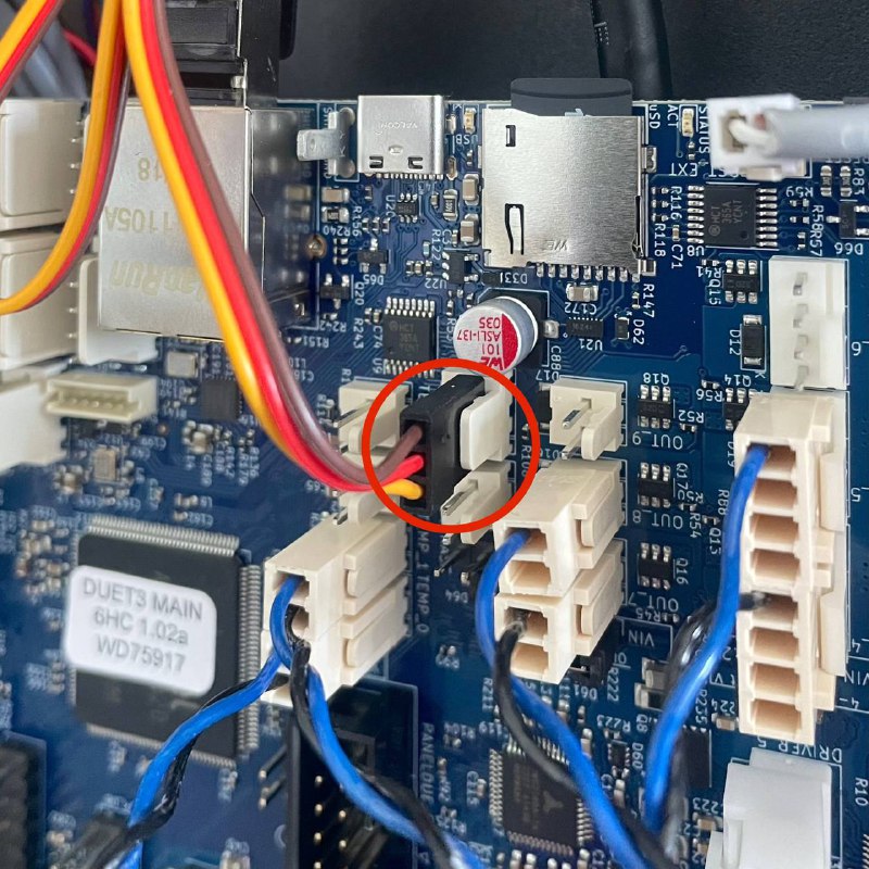
- Gently unplug the wire.
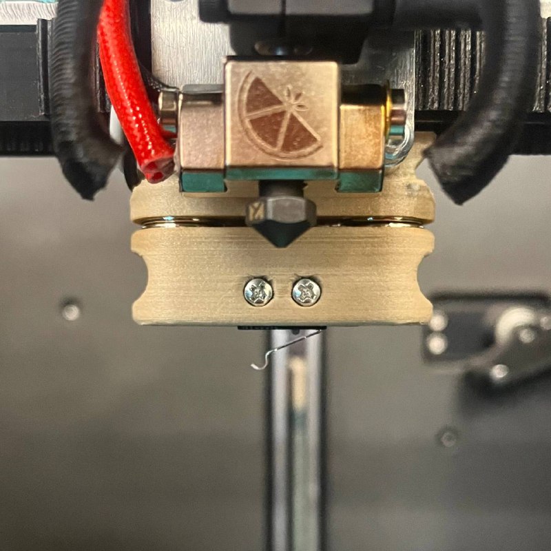
¶ Remove the Probe Docking Station
¶ Access the Servo Motor Screws
- Open the lid of the machine to access the interior.
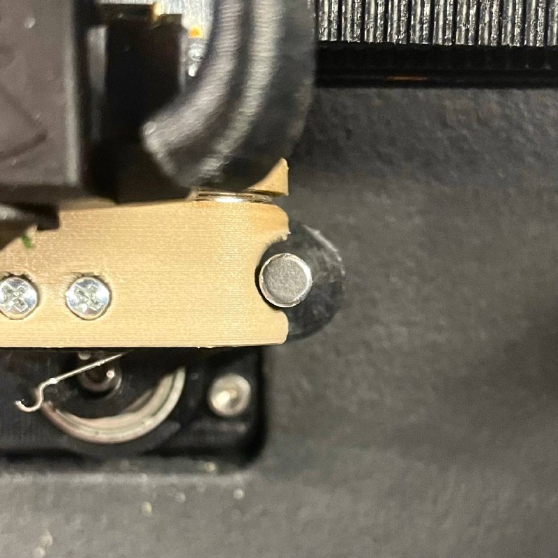
¶ Detach the Docking Station
- Using the 2.5 mm hex screwdriver, remove the screw holding the probe docking station attached to the servo.
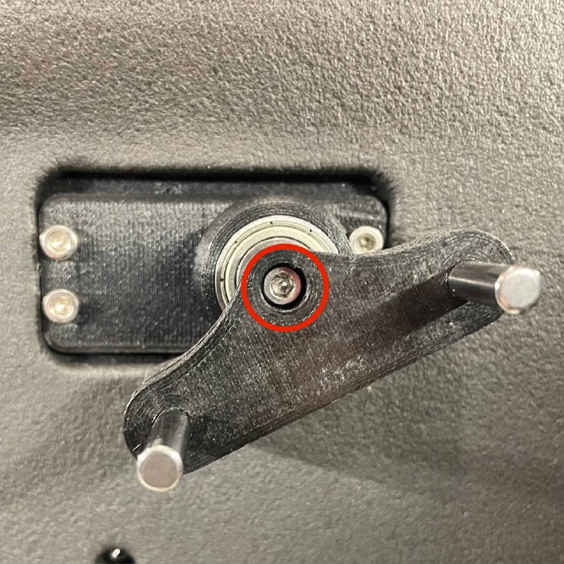
- Pull the docking station towards the front of the machine to remove it.
¶ Remove the Servo Motor
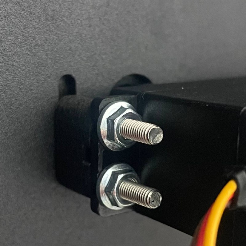
¶ Unscrew the Servo Motor
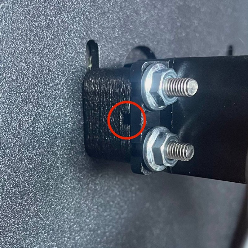
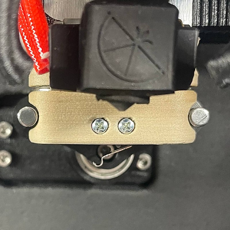
- Locate the four screws securing the servo motor from inside the machine.
- Using the 2.5 mm hex screwdriver, remove the screws while holding the nuts at the back to prevent spinning.
- Carefully slide the servo motor out.
Caution: Be mindful of any wires or components that may obstruct removal.
¶ 3. Installing the New Servo Motor
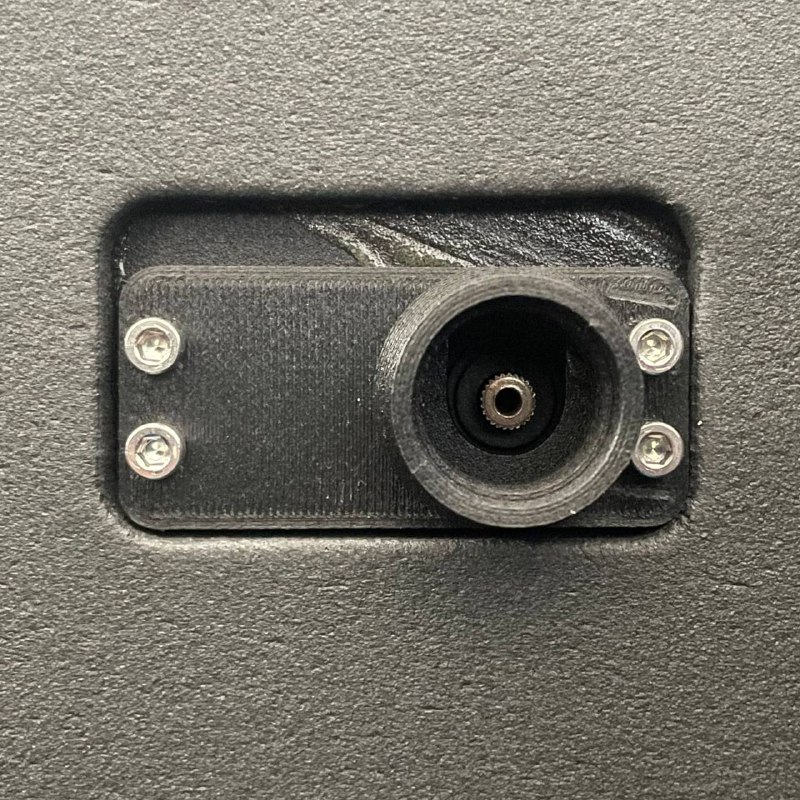
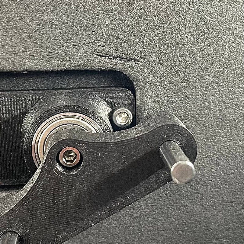
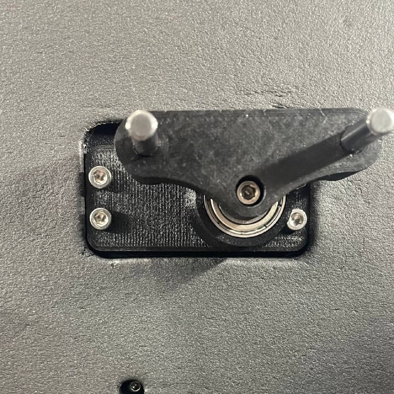
¶ Position the New Servo Motor
- Place the new servo motor into the designated slot.
- Ensure the standoffs and bearing housing are correctly aligned.
¶ Partially Tighten the Screws
- Insert the four screws through the servo motor mounting holes.
- Hand-tighten the nuts at the back just enough to hold the servo in place.
Important: Do not fully tighten the screws; the servo should still move up and down for calibration.
¶ 4. Reconnecting and Securing Components
¶ Reconnect the Servo Wire
- Plug the servo motor wire back into the mainboard, matching the previous connection.
¶ Close the Electronics Bay
- Securely close the rear door.
¶ 5. Calibrating the Servo Motor
¶ Performing the Automated Probe Servo Arm Calibration
This procedure utilizes the built-in macro to configure the servo's position and angle.
¶ 1. Reconnect Power
- Plug the power cord back into the machine.
- Turn on the 3D printer.
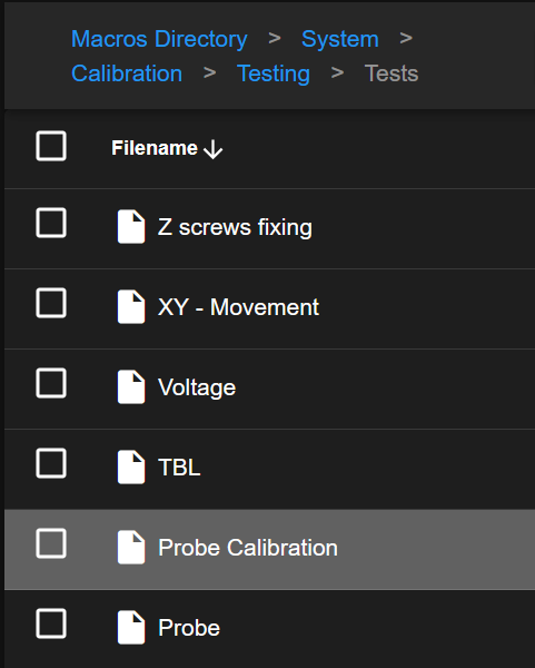
¶ 2. Initiate Calibration Macro
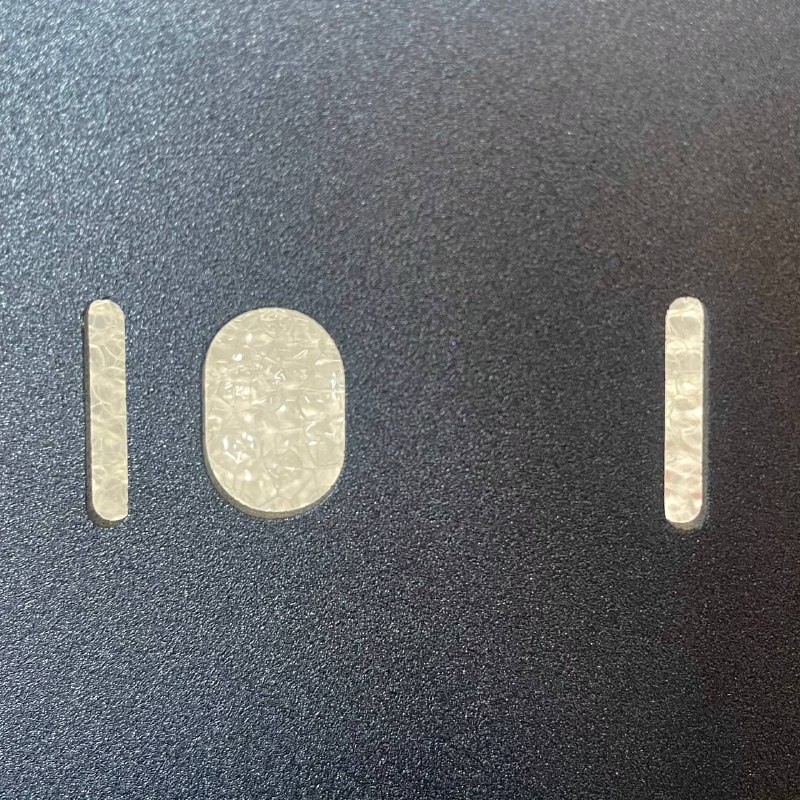
- On the printer's web interface, navigate to the
Macrostab. - Go to the
System > Calibration > Testing > Tests. - Select the
Probe Calibrationmacro.
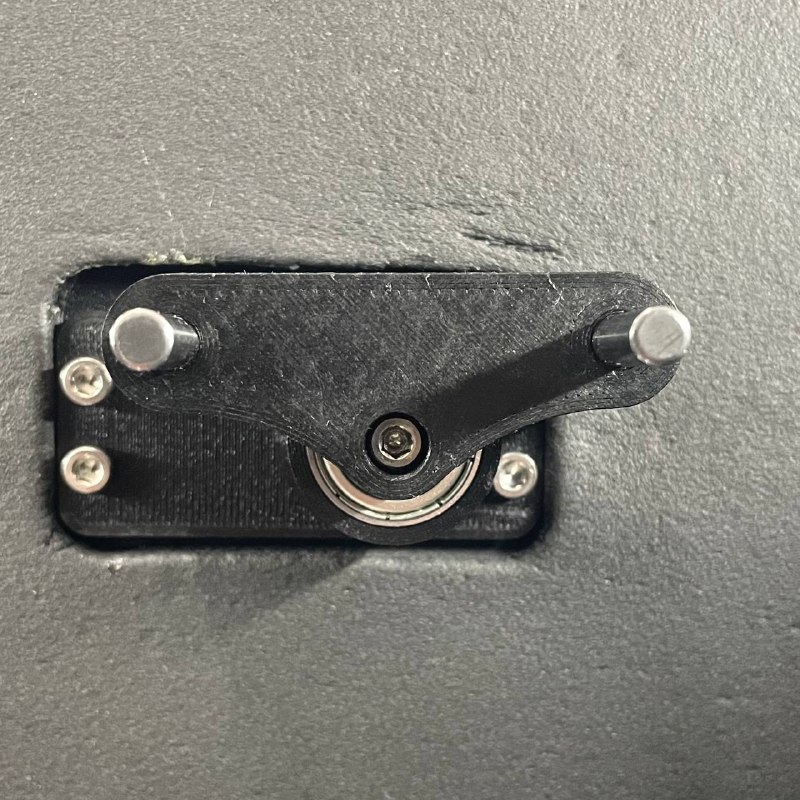
¶ 3. Servo Rotation Check and Dock Station Installation
- The macro will start by rotating the servo shaft. Make sure the rotation is smooth, with no resistance or unusual sounds.
- Mount the dock station onto the servo and tighten it so that it nearly aligns over the top-right screw.
- Follow the on-screen instructions to confirm that the servo motor is rotating correctly.
¶ 4. Initial Angle Adjustment
- The macro will move the servo dock station to a key position (the pick-up/drop-off pose).
- On-screen adjustment buttons (
Adjust the CW/Adjust the CCW) will appear. Use them to precisely adjust the servo's rotation angle until the probe holder arm is perfectly horizontal.
- Confirm the angle adjustment on the screen.
¶ 5. Holder Height Check
- Manually place the detachable Z-probe onto its magnetic mount on the left toolhead.
- Follow the macro instructions: the printer will move the toolhead (with the probe attached) close to the servo dock mechanism.
- Visually inspect the vertical alignment between the servo dock station and the corresponding feature on the probe body. Check if the dock is too high, too low, or correctly aligned to engage the probe properly.
¶ 6. Height Adjustment (If Necessary)
- If Height is CORRECT: Select the
Doneon the screen to skip height calibration. - If Height is INCORRECT:
- Carefully loosen the servo mount fasteners:
- Use the 2.5 mm Hex Driver to loosen the three accessible screws.
- Use the 5.5 mm Wrench to loosen the fourth screw at the rear of the printer mechanism.
- Use the 2.5 mm Hex Driver to loosen the three accessible screws.
- Carefully slide the entire servo mount assembly up or down manually until the dock aligns perfectly in height with the probe (which is still mounted on the toolhead).
- Gently snug the three accessible screws (2.5 mm Hex) – just enough to hold the position.
- Confirm on the screen that the adjustment is complete.
- The macro will move the toolhead away.
- Follow the prompt to fully tighten the three accessible screws (2.5 mm Hex).
- The macro will likely rotate the servo arm to provide access to the fourth screw.
- Follow the prompt to fully tighten the fourth screw (2.5 mm Hex).
- Carefully loosen the servo mount fasteners:
¶ 7. Angle Adjustment
- After the height adjustment (or if it was skipped), the macro proceeds to angle calibration (a repeat of Step 3). Adjust as needed and confirm.
¶ 8. XY Position Adjustment
- The macro prompt for a fine-tuning of the probe position .
- The toolhead will move near the servo dock.
- Use the on-screen adjustment buttons (
+X,-X) to precisely align the servo dock horizontal (XY) position relative to the target position.
- The macro only stores the X position, use Y for easier setup.
- Confirm the XY adjustment on the screen.
¶ 9. Final Check / Test Cycle
- After completing all adjustments, the macro execute an automatic test cycle: attempting to pick up the probe from the dock and then return it.
- Observe this process carefully. Ensure the pick-up and drop-off actions are smooth, precise, and reliable.
- Confirm successful completion on the screen if the problem is solved.
¶ Best Practices
- Regular Maintenance: Periodically check the servo motor and docking station for wear.
- Firmware Updates: Keep your printer’s firmware up to date for optimal performance.
- Gentle Handling: Avoid applying excessive force when adjusting components.
- Documentation: Keep a log of maintenance activities for future reference.
¶ Troubleshooting
-
Servo Motor Not Moving:
- Ensure the servo wire is correctly connected to the mainboard.
- Check for any firmware errors in the web interface.
-
Docking Station Misalignment:
- Repeat the calibration steps to adjust the servo position.
- Verify that the docking station is securely attached.
By carefully following this guide, you can successfully replace and calibrate the servo motor on your 3D printer, ensuring continued precision and reliability in your printing tasks.