¶ Introduction
XY Alignment calibration ensures that both toolheads (T0 and T1) are perfectly aligned when printing multi-material or multi-color parts. This calibration is essential for eliminating gaps, voids, or color misalignment in dual-extruder prints such as soluble supports, multi-color parts, and multi-material prints.
During Auto Calibration, the machine automatically measures the alignment using cutouts in the build plate. However, you should verify and fine-tune this alignment using a test print and live adjustment macros.
¶ When to Perform XY Alignment
You MUST perform XY alignment calibration:
- ✅ After running Auto Calibration
- ✅ Before starting multi-material or multi-color prints
- ✅ After replacing or servicing either toolhead
- ✅ After replacing heat breaks
- ✅ If you notice color shifts or gaps in multi-material prints
You do NOT need to recalibrate:
- ❌ Between prints using the same toolhead configuration
- ❌ When changing materials on already-calibrated toolheads
- ❌ For single-extruder prints
¶ Prerequisites
Before starting XY alignment calibration:
- ✅ Auto Calibration must be completed successfully
- ✅ 0.4mm nozzles installed on both toolheads (required)
- ✅ Two contrasting materials (black and white recommended)
- ✅ Materials must be compatible and stick to each other
- ✅ Same material type for both colors (e.g., PLA black + PLA white)
- ✅ Both toolheads heated to printing temperature
Important: This calibration only works with 0.4mm nozzles. Other nozzle diameters are not supported for this test.
¶ Understanding XY Alignment
¶ How Auto Calibration Works
As part of Auto Calibration, the machine uses cutouts in the build plate to measure alignment:
- Left toolhead (T0) probes to find the center of the cutout
- Right toolhead (T1) probes the same cutout to find its center
- The machine calculates the offset between the two toolheads
- Alignment values are saved automatically
¶ Why Heat Breaks Must Be Straight
Critical Requirement: Heat breaks must not be bent in any direction.
Before performing calibration:
- Visually inspect both heat breaks
- Look at the hotend from the side
- Verify the nozzle points straight down
- Check that the hotend is not bent left, right, forward, or backward
If heat breaks are bent, the nozzles will not align correctly regardless of calibration values.
¶ Part 1: Obtaining the Test Print
¶ Locating the Test File
The XY Alignment test print is pre-loaded on your machine's SD card.
Alternative Method: You can download the XY Alignment test file directly:
Download XY Alignment Test.gcode
-
Access the Web Interface:
- Open your printer's web interface
- Navigate to Jobs
-
Find the Test File:
- Go to Jobs > 0:/gcodes/Slicer/Tests
- Locate XY Alignment Test.gcode
- Download the file to your computer
¶ Preparing the Test File in Your Slicer
-
Open in Slicer:
- Import the downloaded file into your slicer software (PrusaSlicer or compatible)
-
Select Materials:
- Choose contrasting materials for visual clarity
- Recommended: Black and white
- Left toolhead (T0): Assign one color (e.g., black)
- Right toolhead (T1): Assign the other color (e.g., white)
-
Material Requirements:
- Use the same base material type (e.g., both PLA, both PETG, etc.)
- Ensure materials are compatible and will stick to each other
- Set appropriate printing temperatures for your chosen materials
-
Slice and Export:
- Slice the file with your material selections
- Save the G-code back to the SD card or upload to the printer
Pro Tip: High contrast materials (black/white, black/yellow) make alignment verification much easier. Avoid similar colors like dark blue and black.
¶ Part 2: Running the Alignment Test Print
¶ Starting the Print
-
Load Materials:
- Load contrasting materials into both toolheads
- Ensure both are properly loaded and extruding
-
Heat the Toolheads:
- Set temperatures for both materials
- Wait for both hotends to reach target temperature
-
Start the Print:
- Begin printing the prepared XY Alignment test file
- The print will create a cylinder with alternating colors
¶ Understanding the Test Print
What the Print Does:
- Prints a vertical cylinder
- Alternates between T0 and T1 every layer
- Creates two overlapping circles (one from each toolhead)
- Shows alignment along both X-axis and Y-axis
What to Look For:
- The cylinder should have uniform color distribution all around
- No color shift when rotating the part
- Equal amounts of each color visible from all angles
¶ Initial Observation
-
Let It Print:
- Allow the print to run for several layers (at least 10-15 layers)
- This provides enough height to assess alignment
-
Observe the Cylinder:
- Look at the print from all sides (front, back, left, right)
- Check if one color dominates on any particular side
- Rotate your viewing angle to see color distribution
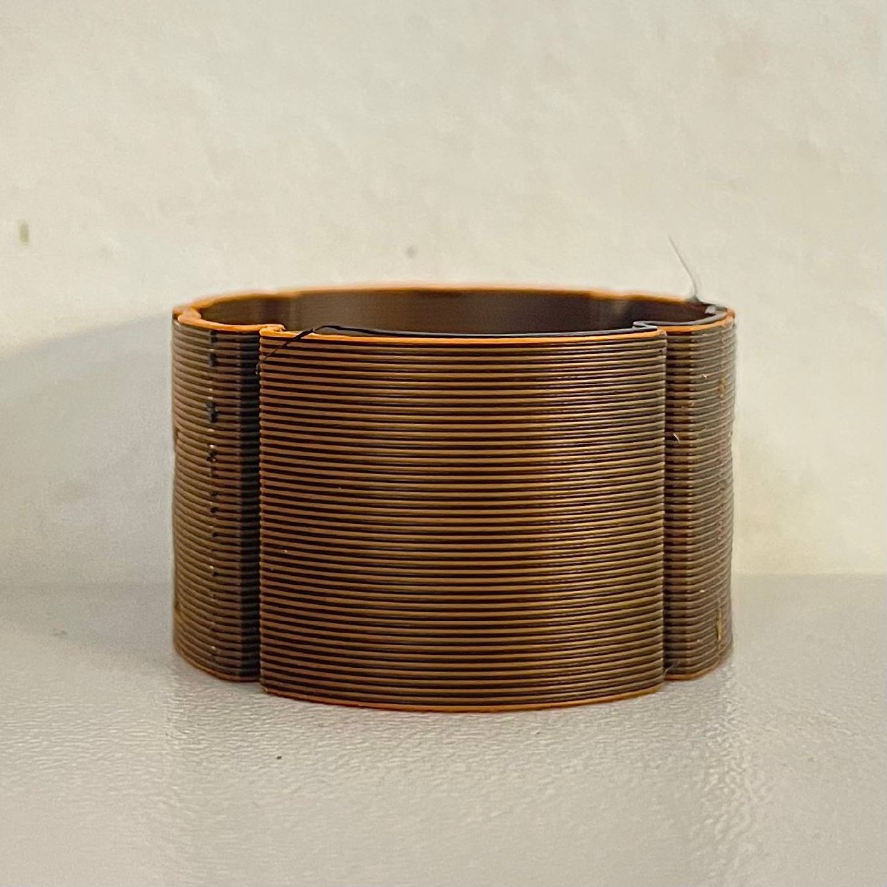
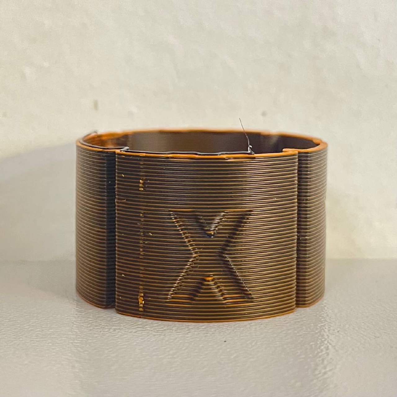
Image: Well-aligned cylinder showing equal color distribution from all angles
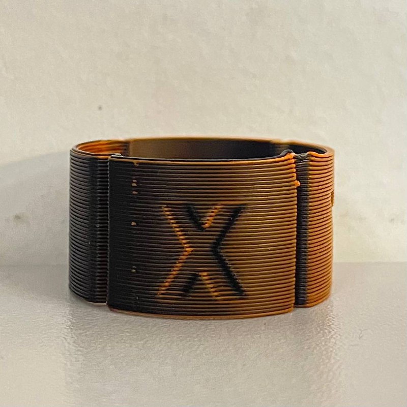
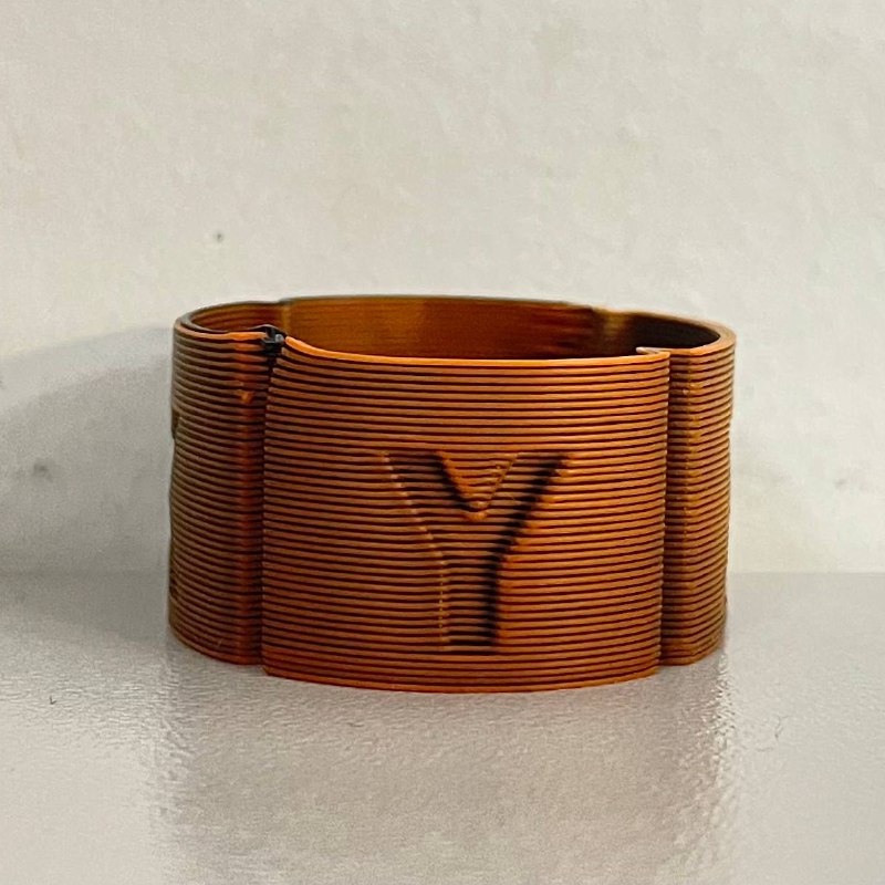
Image: Misaligned cylinder showing more black on one side, indicating need for adjustment
¶ Part 3: Live XY Offset Adjustment
If you notice color imbalance, you can adjust the alignment in real-time while the print continues.
¶ Accessing Live Adjustment Macros
-
Navigate to Macros:
- Open the web interface
- Go to Macros > System > Calibration > Live XY Offset Adjustment
-
Available Adjustment Macros:
- ← Move T1 Left - Moves right toolhead (T1) to the left
- → Move T1 Right - Moves right toolhead (T1) to the right
- ↑ Move T1 Forward - Moves right toolhead (T1) forward
- ↓ Move T1 Backward - Moves right toolhead (T1) backward
Important: You are adjusting the right toolhead (T1) position relative to the left toolhead (T0). The arrows indicate direction when standing in front of the machine.
¶ Understanding the Adjustment Direction
Reading the Test Print:
If you see more black on the right side:
- The right toolhead (T1 with white) is positioned too far right
- Solution: Click ← Move T1 Left
If you see more black on the left side:
- The right toolhead (T1 with white) is positioned too far left
- Solution: Click → Move T1 Right
If you see more black on the front:
- The right toolhead (T1 with white) is positioned too far forward
- Solution: Click ↓ Move T1 Backward
If you see more black on the back:
- The right toolhead (T1 with white) is positioned too far back
- Solution: Click ↑ Move T1 Forward
¶ Making Adjustments
Adjustment Process:
-
Identify Misalignment:
- Determine which side shows more of one color
- Decide which direction to move T1
-
Click the Appropriate Macro:
- Each click moves the toolhead by 0.05mm
- Changes are applied immediately
- Offset values are saved automatically
-
Observe the Change:
- Watch the next few layers being printed
- Check if the color distribution improves
- Continue adjusting as needed
-
Fine-Tune:
- Make small adjustments (1-2 clicks at a time)
- Allow a few layers to print between adjustments to see the effect
- Continue until color distribution is uniform
Example Adjustment Sequence:
- Notice more yellow on the left side of cylinder
- Click → Move T1 Right twice
- Print 3-4 more layers
- Check color distribution
- Click ↑ Move T1 Forward once for final fine-tuning
- Verify color is now uniform all around
¶ Automatic Saving
Note: All offset changes are saved automatically. You do not need to manually save or confirm changes.
The macros automatically update the following files:
0:/user/uoffset.g- X-axis offset (U-axis)0:/user/yoffset.g- Y-axis offset0:/user/tooloffset.g- Combined tool offset values
¶ Part 4: Verifying Alignment
¶ Final Inspection
Once you're satisfied with the adjustments:
-
Let the Print Complete:
- Allow the cylinder to finish printing
- A completed print provides the best verification
-
Visual Inspection:
- Remove the print from the bed
- Rotate the cylinder slowly
- Observe color distribution from all angles
-
Check All Axes:
- X-axis alignment: Look along the front-back direction
- Y-axis alignment: Look along the left-right direction
- Colors should appear equal from all viewing angles

¶ Acceptable Results
Well-Aligned Print:
- ✅ Uniform color distribution when rotating the part
- ✅ No visible color shift on any side
- ✅ Equal amounts of both colors visible from all angles
- ✅ Clean, sharp transitions between colors
Needs Further Adjustment:
- ❌ One color dominates on specific sides
- ❌ Visible shift in color as you rotate the part
- ❌ Gaps or overlaps visible between colors
¶ Troubleshooting
¶ Colors Don't Blend or Stick Together
Problem: The two materials are separating or not adhering.
Solutions:
- Verify both materials are compatible (same base material)
- Increase printing temperature slightly for better layer adhesion
- Ensure bed temperature is appropriate for both materials
- Clean nozzles to remove any contamination
¶ Adjustment Has No Effect
Problem: Clicking adjustment macros doesn't change the print.
Solutions:
- Allow 3-4 layers to print after adjustment to see the effect
- Verify macros are executing (check console for confirmation)
- Ensure you're adjusting the correct axis for the observed problem
- Check that heat breaks are straight and not bent
¶ Alignment Changes Between Prints
Problem: Alignment is good on one print but off on the next.
Solutions:
- Always run Auto Calibration before multi-material prints
- Check for loose toolhead components
- Verify heat breaks are properly seated and not bent
- Inspect X-axis and U-axis belts for proper tension
¶ Cannot Achieve Perfect Alignment
Problem: Alignment is close but never perfect regardless of adjustments.
Solutions:
- Verify 0.4mm nozzles are installed (other sizes not supported)
- Check heat breaks for bending or damage
- Inspect nozzles for wear or damage
- Ensure both toolheads are properly assembled
- Contact support if alignment cannot be achieved within ±0.1mm
¶ Understanding the Adjustment Values
¶ How Adjustments Work
Each click of an adjustment macro changes the offset by 0.05mm:
-
U-axis offset (X-direction):
- Move Left: Increases
global.uoffsetby 0.05mm - Move Right: Decreases
global.uoffsetby 0.05mm
- Move Left: Increases
-
Y-axis offset:
- Move Forward: Decreases
global.yoffsetby 0.05mm - Move Backward: Increases
global.yoffsetby 0.05mm
- Move Forward: Decreases
¶ Checking Current Offsets
After each adjustment, the console displays current offset values:
Current offsets: U[value] Y[value] Z[value]
You can monitor these values to track your adjustments.
¶ Auto Calibration Background
¶ How XY Auto Squaring Works (Advanced)
The Auto Calibration system uses three cutout holes in the build plate:
- Left Rear (LR) hole - Measured with T1
- Right Rear (RR) hole - Measured with T1
- Right Front (RF) hole - Measured with T1
The system:
- Probes each hole to find the center coordinates
- Calculates the angle and distance between holes
- Determines the correction needed for square alignment
- Saves the correction value automatically
Auto vs. Manual Mode:
- Auto mode: Uses calculated correction from Auto Calibration
- Manual mode: Uses manually entered correction value
- The system respects your mode selection
¶ Best Practices
- Always run Auto Calibration first - Live XY adjustment is for fine-tuning only
- Use high-contrast materials - Makes visual inspection much easier
- Print multiple test cylinders - Verify consistency across multiple prints
- Make small adjustments - 1-2 clicks at a time, then observe results
- Document your offsets - Note final values for reference
- Recalibrate after maintenance - Any toolhead work requires new calibration
- Check heat breaks regularly - Ensure they remain straight and undamaged
¶ When to Contact Support
Contact Vision Miner support if:
- Alignment cannot be achieved after multiple attempts
- Heat breaks appear bent or damaged
- Auto Calibration fails repeatedly
- Offset values drift significantly between prints
- Physical damage to toolheads or probe system
¶ Summary
XY Alignment calibration ensures perfect overlap of both toolheads for multi-material and multi-color prints. By running the XY Alignment test print with contrasting materials and using the live adjustment macros, you can achieve precise alignment with uniform color distribution.
Remember: Always run Auto Calibration first, then verify and fine-tune using the test print. The alignment values are saved automatically and will persist until the next Auto Calibration or manual adjustment.