¶ Troubleshooting Endstop Issues
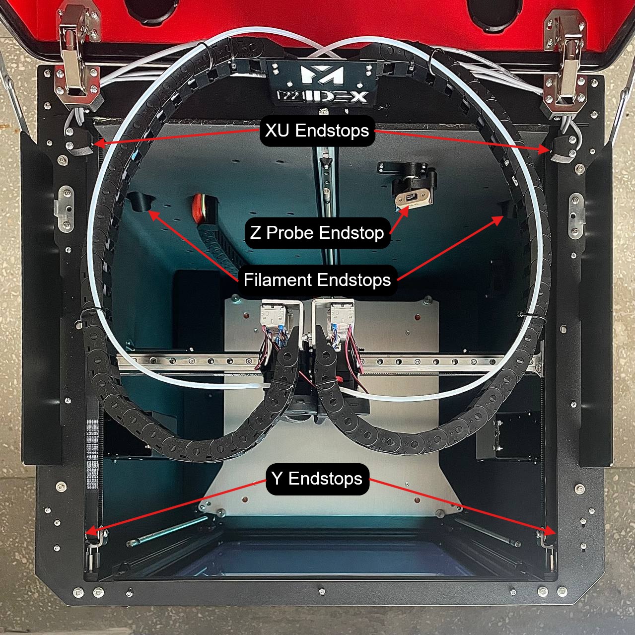
Endstops are crucial components of a 3D printer that define the home positions of moving parts and, in some cases, detect the presence of filament. The Vision Miner 22IDEX is equipped with 7 endstops:
- 1x X-axis endstop
- 1x U-axis endstop (opposite the X endstop, for the second X-carriage)
- 2x Y-axis endstops (one on each side of the Y-axis)
- 2x filament sensors (one for each extruder, T0 and T1)
- 1x Z-probe (used as an endstop for Z-axis homing and bed leveling)
A malfunction in any of these endstops can lead to printing problems or even damage to the printer. This article will help you diagnose and resolve common issues related to X, Y, U axis endstops, the Z-probe, and filament sensors.
¶ Symptoms of Endstop Problems
¶ X, U, Y Axis Endstops and Z-Probe:
- Symptom: During the "homing" procedure, the corresponding axis (X, U, Y), print head, or build plate continues to move even after reaching the physical end of its travel or triggering the endstop. This may be accompanied by a grinding or skipping sound from the motors. For the Z-probe, this might manifest as the nozzle crashing into the bed during Z-homing or calibration.
¶ Filament Sensors:
- Symptom: The printer incorrectly reports that filament has run out and pauses the print, even though filament is still present and loaded. In other cases, the sensor may trigger erratically during a print, despite functioning correctly during manual checks.
¶ Diagnostics
The first step in resolving any endstop issue is to check its electrical functionality using the printer's interface.
¶ Step 1: Checking Endstop Operation in the Printer Interface
¶ For X, U, and Y Axis Endstops:
- Navigate to the
Pluginstab in your printer's web interface. - Enable the
Object Model Browserplugin if it's not already active.
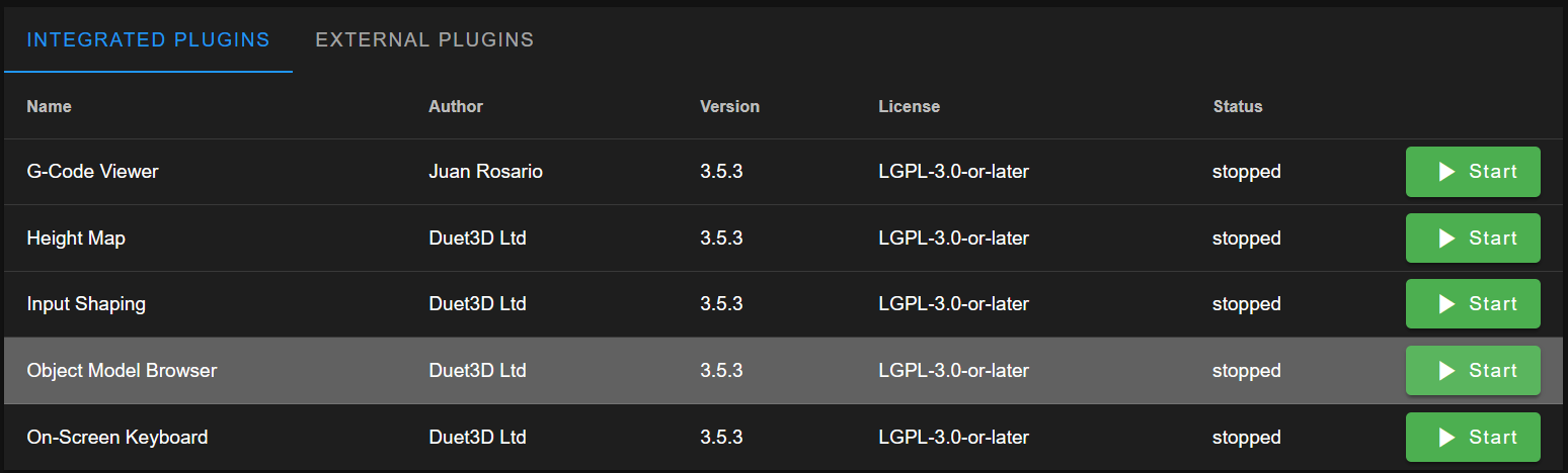
- Go to the newly available
Object Model Browsertab. - In the list that appears, find and expand the
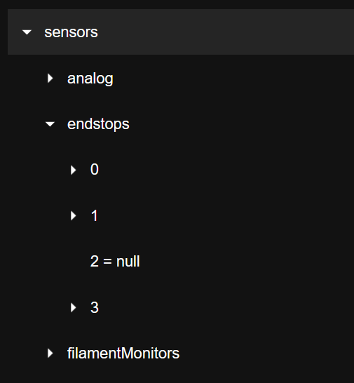
sensorsitem. - Next, expand the
endstopsitem. You will see several drop-down lists. The relevant ones for axis endstops are typically:0: Corresponds to the X-axis endstop.1: Corresponds to both Y-axis endstops (pressing either Y endstop should trigger this).3: Corresponds to the U-axis endstop.
- In each of these lists, find the field
triggered. Its value (trueorfalse) changes in real-time.
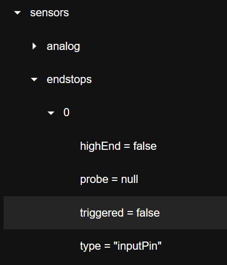
- Manually and gently press the corresponding physical endstop switch on the printer. The
triggeredvalue in the interface should change when the endstop is pressed and change back when released.- For the X-axis endstop, press it – the
triggeredvalue for list0should change. - For the U-axis endstop, press it – the
triggeredvalue for list3should change. - For the Y-axis endstops, press either of the two physical Y endstops – the
triggeredvalue for list1should change.
- For the X-axis endstop, press it – the
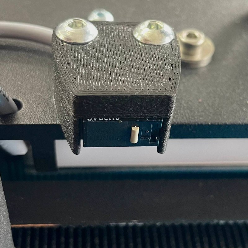
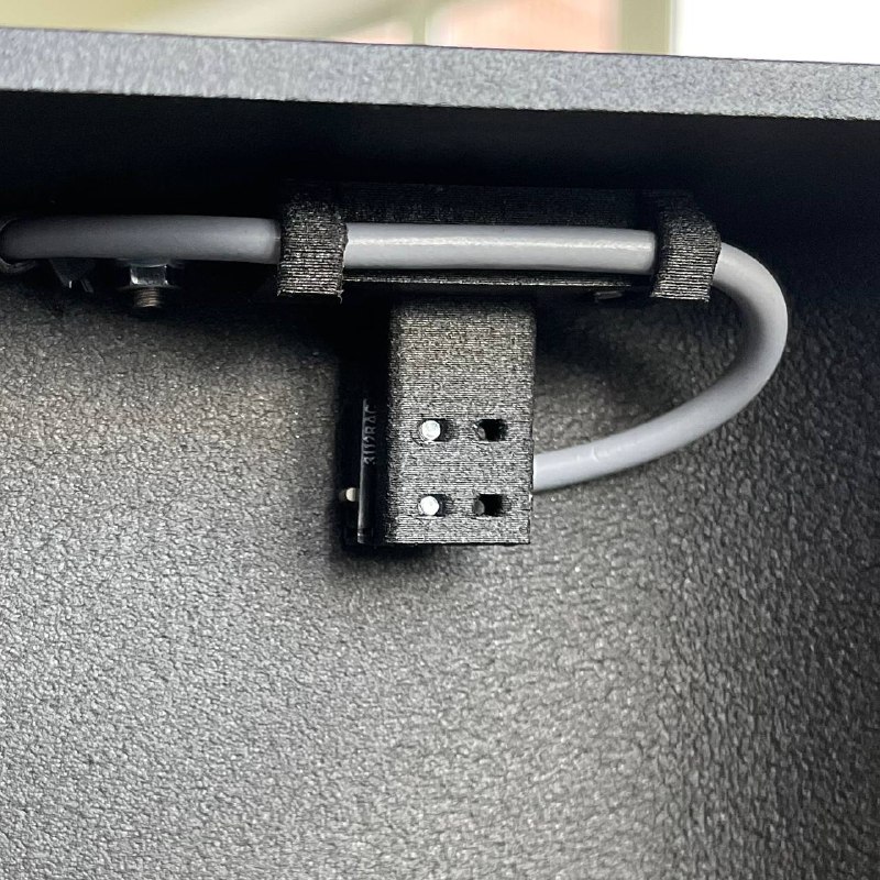
¶ For the Z-Probe:
- Navigate to the
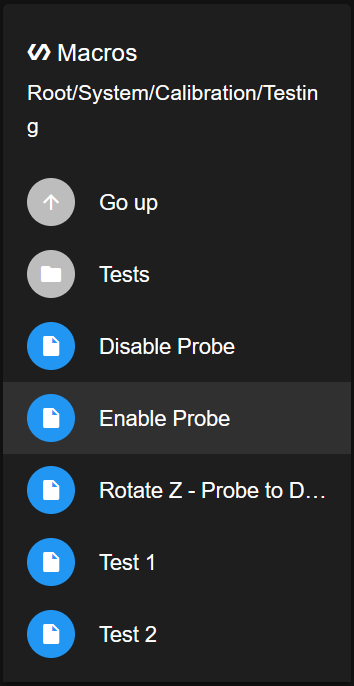
Dashboardtab in the printer's interface. - In the
Macroswindow, find theSystemsection, thenCalibration, thenTesting. - Click the
Enable Probebutton.
- Carefully take the Z-probe and install it onto the designated mounting position on the print head, as you would during a normal calibration procedure.
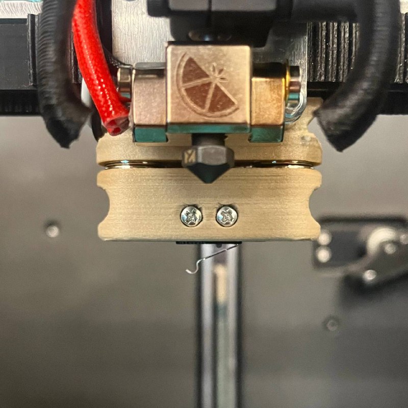
- In the
Statuswindow on theDashboard, find theZ Probefield.
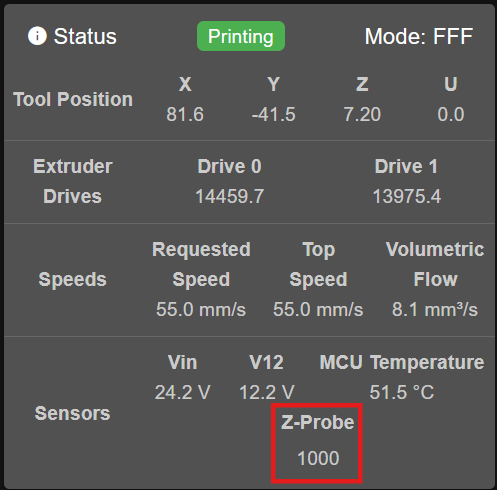
- Gently press the mechanical tip of the Z-probe. The value of the
Z Probefield should change: typically reading1000when the probe is not pressed, and0when its tip is pressed.
If the Z-Probe shows correct electrical response here but issues persist during operation (e.g., calibration failures, nozzle crashing), further specific troubleshooting is required.
- Troubleshooting Z-probe: Link to Z-Probe Troubleshooting Guide Here
¶ Step 2: Actions Based on Test Results for X, U, Y Axis Endstops
This section applies if issues persist with X, U, or Y axis homing or movement, based on the interface tests.
¶ If the X, U, or Y endstop is NOT working (value in the interface does not change when physically pressed):
- Check the connector:
- Power off the printer.
- Carefully locate and unplug the connector of the respective endstop from its socket on the printer's mainboard.
- Inspect the metal pins (contacts) inside the connector and on the mainboard socket. Ensure they have not pulled out of the connector housing, are not bent, broken, or oxidized.
- If the pins and socket look normal, firmly plug the connector back into its socket on the mainboard.
- Power on the printer and re-test the endstop operation via the interface (Step 1 for X, U, Y Axis Endstops).
- Replace the endstop:
- If checking the connector and wiring does not resolve the issue, the endstop switch itself is likely faulty and needs to be replaced with a new, compatible one.
¶ If the X, U, or Y endstop IS working electrically (value in the interface changes correctly), but the physical homing problem persists:
- Check for physical obstructions:
- Carefully inspect the entire travel path of the respective axis (X, U, or Y rail/carriage). Ensure that nothing is physically obstructing its free movement towards the endstop switch (e.g., foreign objects, debris, improperly routed cables, or other components).
- Special attention for X and U endstops: Verify that these endstops or their mounts are not catching on or being prematurely triggered by the flexible cable chain. The cable chain can sometimes shift or sag, interfering with the normal operation or triggering point of the endstop.
- Inspect the endstop's printed mounting parts:
- Axis endstops are usually attached to dedicated 3D printed parts on the printer's frame. Carefully inspect these mounting parts for any signs of cracks, deformations, breaks, or if they have become loose. A damaged or loose mount can cause the endstop to trigger incorrectly, inconsistently, or not at the correct physical position.
- If a mounting part is found to be damaged or broken, it must be replaced with a new, correctly printed one.
¶ Filament Sensor Problems
This section addresses issues where the printer incorrectly reports filament status.
¶ Symptom:
The filament sensor triggers an alert (e.g., "filament out") and pauses the print, even though filament is loaded and appears to be feeding. This may occur randomly during printing, even if the sensor seems to work correctly during manual checks.
¶ Checks:
- Manual Check via Printer Interface:
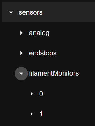
- In the
Object Model Browsertab (as accessed for axis endstops), under the expandedsensorslist, find and expand thefilamentMonitorsitem. - You will typically see two drop-down lists:
0: Corresponds to the first filament sensor (e.g., for T0).1: Corresponds to the second filament sensor (e.g., for T1).
- In each list, find the
statusfield. It can have values likeok(indicating filament is present and detected) ornoFilament(indicating filament is absent). This status should update in real-time.
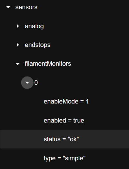
- Slowly insert a piece of filament through the respective sensor. The
statusvalue should change fromnoFilamenttook. Remove the filament; it should change back. Repeat this a few times to confirm consistent electrical operation. You can also try gently pressing any small lever or switch on the sensor if its design allows direct mechanical actuation for testing.
- In the
- Check Connector:
- Power off the printer.
- Inspect the filament sensor's electrical connector, both at the sensor end and where it connects to the mainboard or an intermediary board. Ensure it is securely plugged in and that pins are not damaged, bent, or corroded.
¶ Solutions:
If the filament sensor passes the manual electrical checks above but still triggers incorrectly during printing:
- Reprint Sensor Housing:
- This issue can often be caused by minor dimensional inaccuracies or wear in the 3D printed housing of the filament sensor, causing the filament or sensing mechanism to stick intermittently during the dynamic conditions of printing.
- We recommend reprinting the filament sensor housing using the latest official STL file.
- Ensure the part is printed accurately, possibly with good cooling, as per any specific printing recommendations for that part.
- Request Replacement Housing:
- Alternatively, Vision Miner can send you a replacement sensor housing free of charge if your printer is affected by this common issue.
- Please Contact Vision Miner Support with your original printer order number and a description of the problem to request a replacement.
- Inspect Filament Path & Filament:
- Ensure the filament itself has a consistent diameter and is free of kinks or severe bends where it passes through the sensor.
- Check that the filament feeds smoothly into and out of the sensor, without excessive friction or snagging on the housing or surrounding parts.
- Troubleshooting Filament Sensor Errors: Link to Filament Sensor Troubleshooting Guide Here
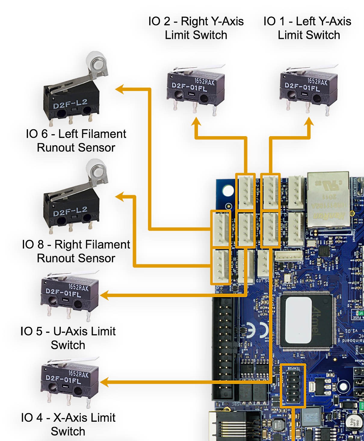
¶ Quick Reference: Endstop Locations
For ease of identification during troubleshooting, refer to this general layout of endstops on the Vision Miner 22IDEX:
If issues persist after following these diagnostic steps, specific components may require replacement or more in-depth technical assistance. Links to contact support have been provided for specific scenarios.