Bridging
Fix sagging, broken or rough bridges — bridge fan speed, flow ratio calibration from 0.95, bridge speed, thick bridges and bridge angle, with tested ranges.
Bridging is the process of printing a horizontal span of filament across an open gap between two points without the use of support material. Mastering this technique is essential for printing complex models efficiently, as it reduces material waste and post-processing time. This guide details how to identify and solve common bridging problems to achieve clean, straight bridges with your Vision Miner 22IDEX V4.
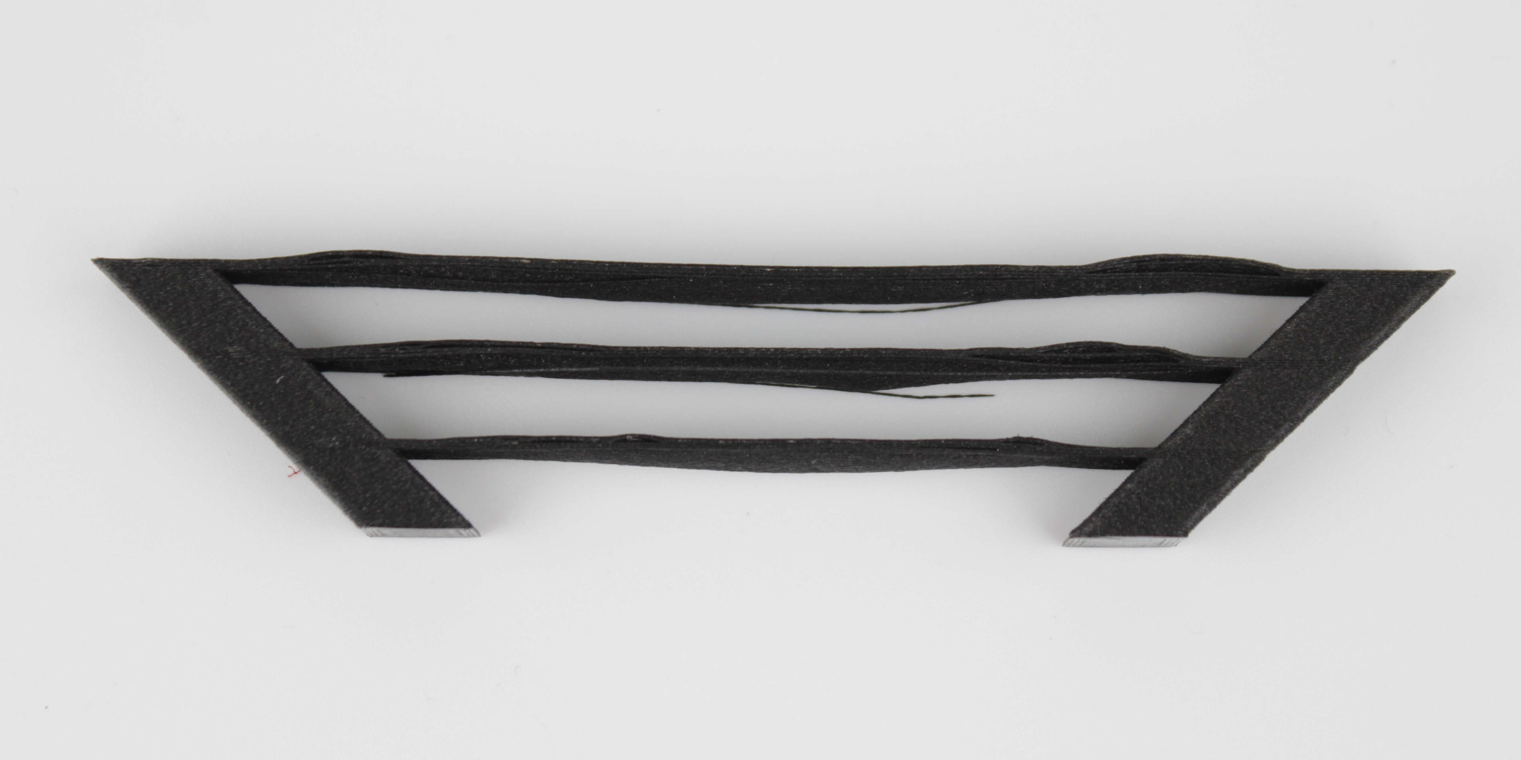
Common Bridging Problems and Solutions
Even with a high-performance printer, achieving perfect bridges requires fine-tuning. Here are the most common issues and how to resolve them.
1. Sagging or Drooping Strands
This is the most frequent bridging issue, where the extruded lines hang downwards instead of forming a straight path.
- Cause: The filament is not cooling fast enough, remaining too molten to hold its shape under gravity. This can be due to excessive printing temperature, insufficient fan speed, or printing too slowly.
- Solution:
- Increase Cooling: Raise the "Bridging Fan Speed" in your slicer step by step, going as high as
100%if your material tolerates it. Proper cooling is the single most important factor for good bridges. - Lower Nozzle Temperature: Reduce the printing temperature in
5°Cincrements. A cooler filament will solidify much faster. Find the lowest temperature your material can reliably extrude at. - Adjust Print Speed: While counterintuitive, sometimes a faster bridging speed can help by stretching the filament taut across the gap. Conversely, if the filament breaks, a slower speed may be needed. This parameter often requires experimentation.
- Increase Cooling: Raise the "Bridging Fan Speed" in your slicer step by step, going as high as
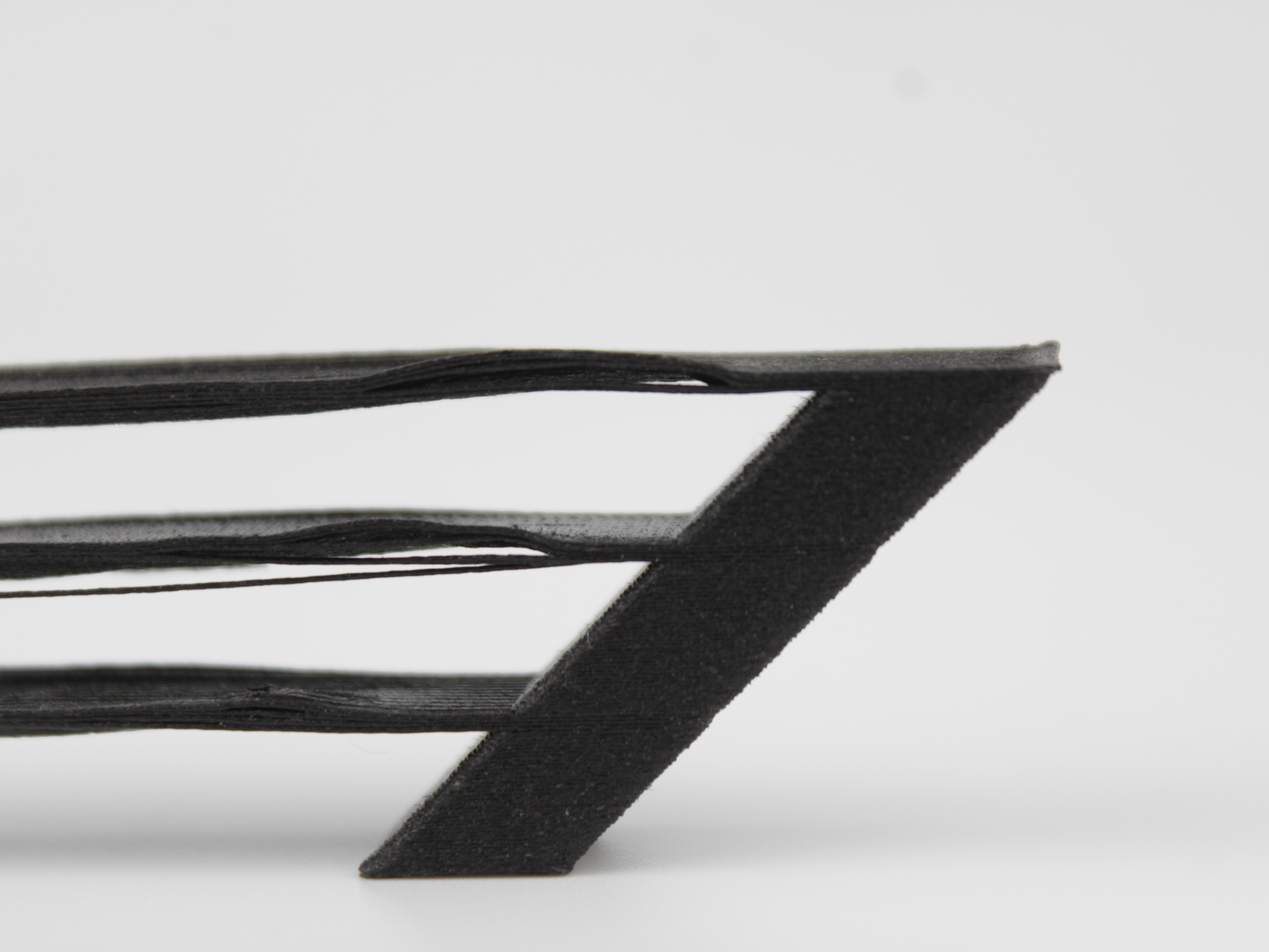
2. Broken or Incomplete Bridge Layers
The initial bridge lines fail to connect, resulting in a broken or non-existent surface.
- Cause: The strand is not landing as a continuous line across the gap, either because the bridging speed is too high for the material to anchor properly, or because the flow is wrong for the span.
- Solution:
- Calibrate Bridge flow ratio. In PrusaSlicer this lives under
Print Settings > Advanced > Flow > Bridge flow ratio. The Vision Miner profiles ship it at1.5and that is what you print with day to day. If bridges are giving you trouble, do not guess from there: drop to0.95as your calibration starting point, print a test, and work back up until the strands are clean. Prusa recommends the same0.95as a starting value. - Reduce Bridging Speed: Slowing down gives the filament more time to anchor itself on both sides of the gap before the print head moves across.
- Calibrate Bridge flow ratio. In PrusaSlicer this lives under
More flow is not the fix for sagging bridges
It is tempting to keep raising the flow until bridges look solid, but past a point extra plastic makes things worse, not better. A heavier strand sags further under its own weight, so bridges that droop call for less material, not more.
That is why calibration starts at 0.95 rather than above the 1.5 default: you come up to a good value from below instead of pushing past it. Treat 2.0 as an absolute ceiling. Beyond it the strands sag badly no matter what else you change.
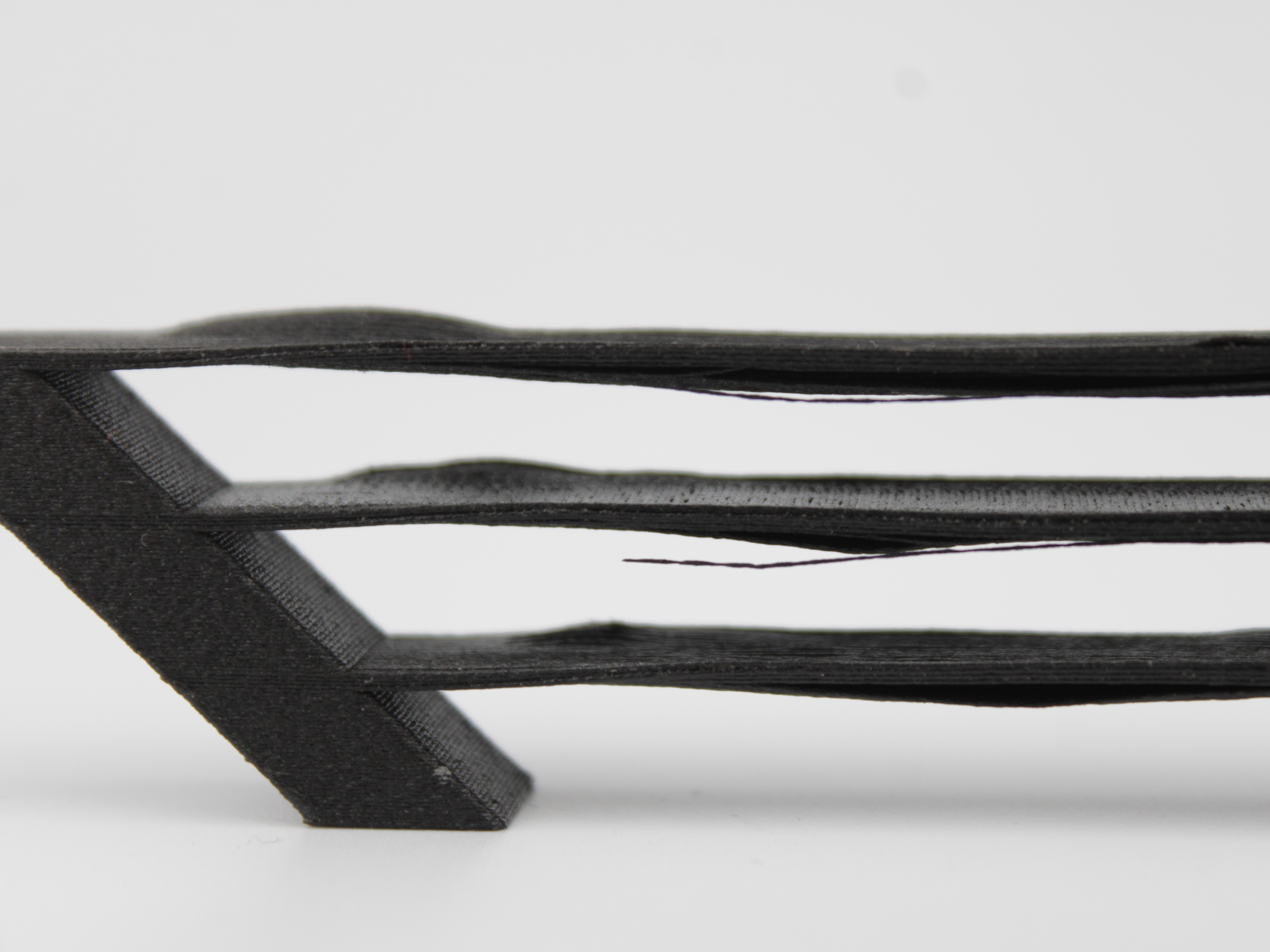
3. Rough Surface on Top of Bridges
The layers printed on top of the initial bridge layer are messy or uneven.
- Cause: The foundation layer of the bridge was not solid enough, providing a poor base for subsequent layers.
- Solution: Turn on Thick bridges, in
Print Settings > Layers and perimeters > Quality. It is off in the Vision Miner profiles.
What Thick bridges actually does
For historical reasons PrusaSlicer used to print bridges with unusually thick lines. That makes the bridge very reliable and lets it span longer gaps, but it does not look good.
The modern default behaviour instead uses the current layer height for the bridge. That is reliable over shorter distances and looks considerably better, and it is the strategy most current slicers use. Thick bridges switches back to the old behaviour.
You do not set a number of layers for this. It is a single on/off switch, and the layer count is not something you choose. The first solid layer above supports uses the bridging settings too, so this option also has a large effect on how supported overhangs look.
Bridges may not appear until you also turn off Detect bridging perimeters
On a model where the slicer does not generate bridges by itself, enabling Thick bridges alone may change nothing visible. Also uncheck Detect bridging perimeters in the same section. With that combination the bridges show up on the model and the bridging settings start to apply.
Key Slicer Settings for Optimal Bridging
Fine-tune these parameters in your slicer software for the best results. The exact names may vary between slicers (e.g., PrusaSlicer, Cura, Simplify3D).
The values below are what we have actually tested on the 22IDEX V4, not generic slicer advice. The Profile default column is what the Vision Miner profiles ship with, so you can see how far a recommendation moves you from your starting point.
| Parameter | Profile default | Start calibration at | Tested range | What it does |
|---|---|---|---|---|
| Bridge fan speed | 100% | 100% | 80-100% | Cooling solidifies the strand before it can sag. The single most important setting. Lower it only if the material cannot take the cooling. |
| Bridge speed | 30 mm/s | 10 mm/s | 10-30 mm/s | How fast the nozzle crosses the gap. Slower gives the strand time to anchor on both sides. |
| Bridge flow ratio | 1.5 | 0.95 | 0.7-1.5 | How much plastic goes into each strand. Keep the default for normal printing; start a calibration from 0.95 and come up. |
| Thick bridges | Off | Off | On or off | Switches to the old thick-line bridging. More reliable and spans further, but looks worse. On/off only, no layer count. |
| Bridge angle | 0 (automatic) | 0 (automatic) | 0 or 180 | The direction the strands run. Leave it automatic unless the slicer picks a bad direction. |
How to read the two value columns
Profile default is what ships in the Vision Miner profiles and what you should print with normally. There is no need to change anything until bridges actually give you problems.
Start calibration at is where to begin tuning once they do. For flow that means dropping to 0.95 and working upwards until the strands come out clean, rather than nudging the 1.5 default around blindly.
As always, test on your own material. These are the numbers we have verified, not a guarantee for every filament.
Where these live in PrusaSlicer. Fan speed is in Filament Settings > Cooling. Bridge speed is in Print Settings > Speed. Bridge flow ratio is in Print Settings > Advanced > Flow. Thick bridges and Detect bridging perimeters are both in Print Settings > Layers and perimeters > Quality. Bridge angle is in Print Settings > Infill.
Bridge angle
The slicer tries to find the shortest path for a bridge. That is usually right, but not always. Rotating the angle by hand lets you line the strands up with the thicker, stronger regions of your model, or shorten the distance they have to span.
The profile default is 0, which means the slicer decides. Setting 180 flips the direction, which on some geometries gives a noticeably shorter span. It only affects Bridge and Bridge infill extrusions, so if your model has no bridges to begin with, changing the angle does nothing. In that case use Thick bridges first, as described above, to make bridges appear at all.
A note on bridge anchors
If PrusaSlicer warns you about floating bridge anchors, it means your walls are too thick, so the bridge begins printing over empty space instead of over solid material.
The fix is to give the bridge more solid infill to land on: reduce Perimeters in Print Settings > Layers and perimeters, for example from 4 to 2. Test this before using it on a real part, since fewer perimeters also means a weaker wall.
High fan speeds with temperature-sensitive materials
While 100% fan speed is ideal for bridging with materials like PLA and PETG, it can cause layer adhesion issues or warping with materials like ABS or ASA. For these materials, use the highest fan speed possible without compromising the overall print integrity.
Our own ABS testing showed this trade-off directly. Bridges printed at 10 mm/s with a bridge flow ratio of 0.7 and 100% cooling came out well, but the cooling was strong enough that the strands did not bond to each other as well as they should, and the nozzle temperature had to be raised to compensate. If you are running heavy cooling on a warp-prone material, expect to give some temperature back.
Tested settings on high-temperature materials
Bridging on filled, high-temperature engineering materials tends to be treated as hopeless. It is not, but the settings differ from what works on PLA.
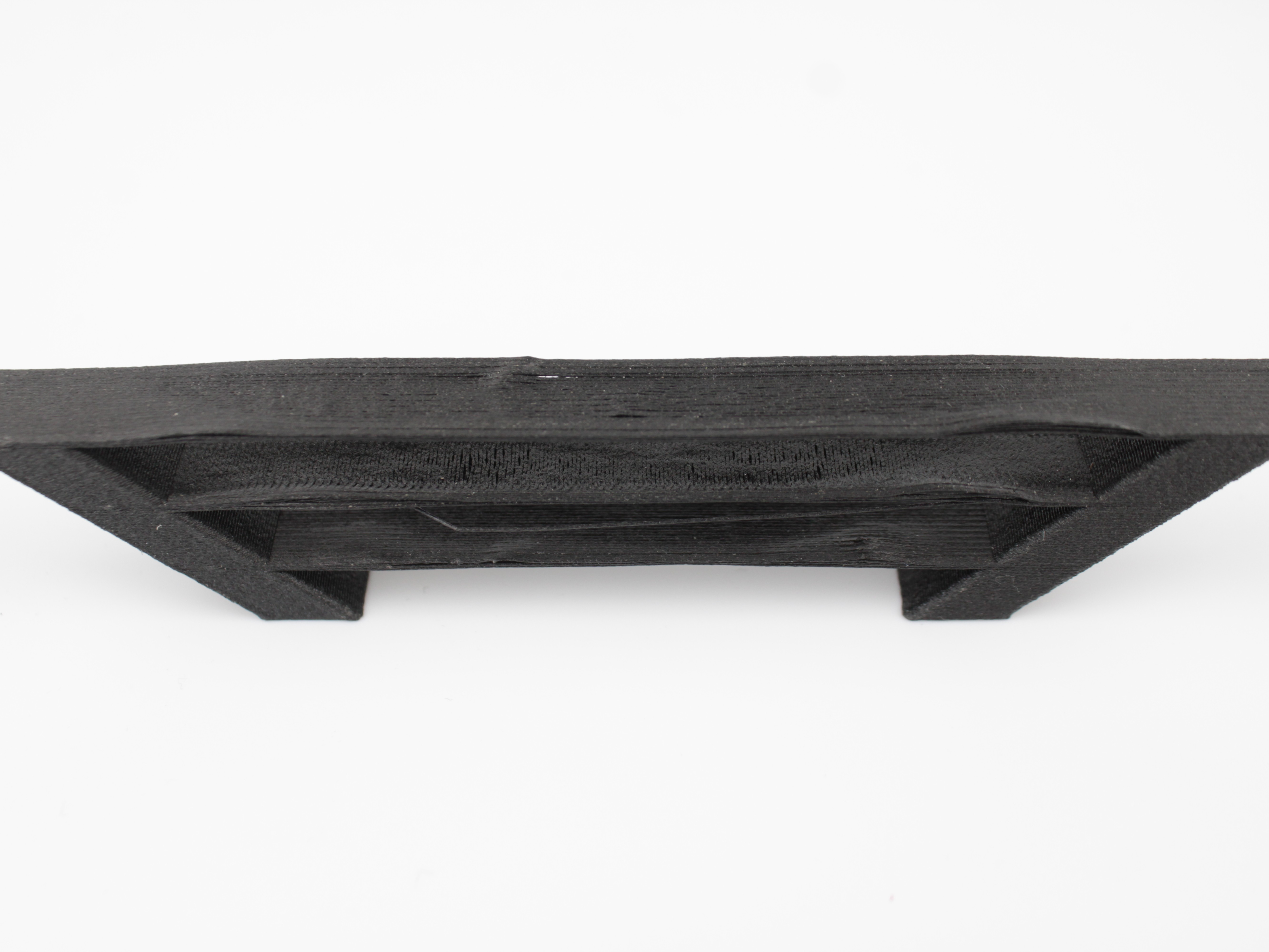
The bridge below was printed in PPS+CF10, a carbon-filled high-temperature material that melts around 370 °C, using:
| Setting | Value |
|---|---|
| Thick bridges | On |
| Bridge flow ratio | 0.7 |
| Bridge speed | 10 mm/s |
| Bridge fan speed | 80% |
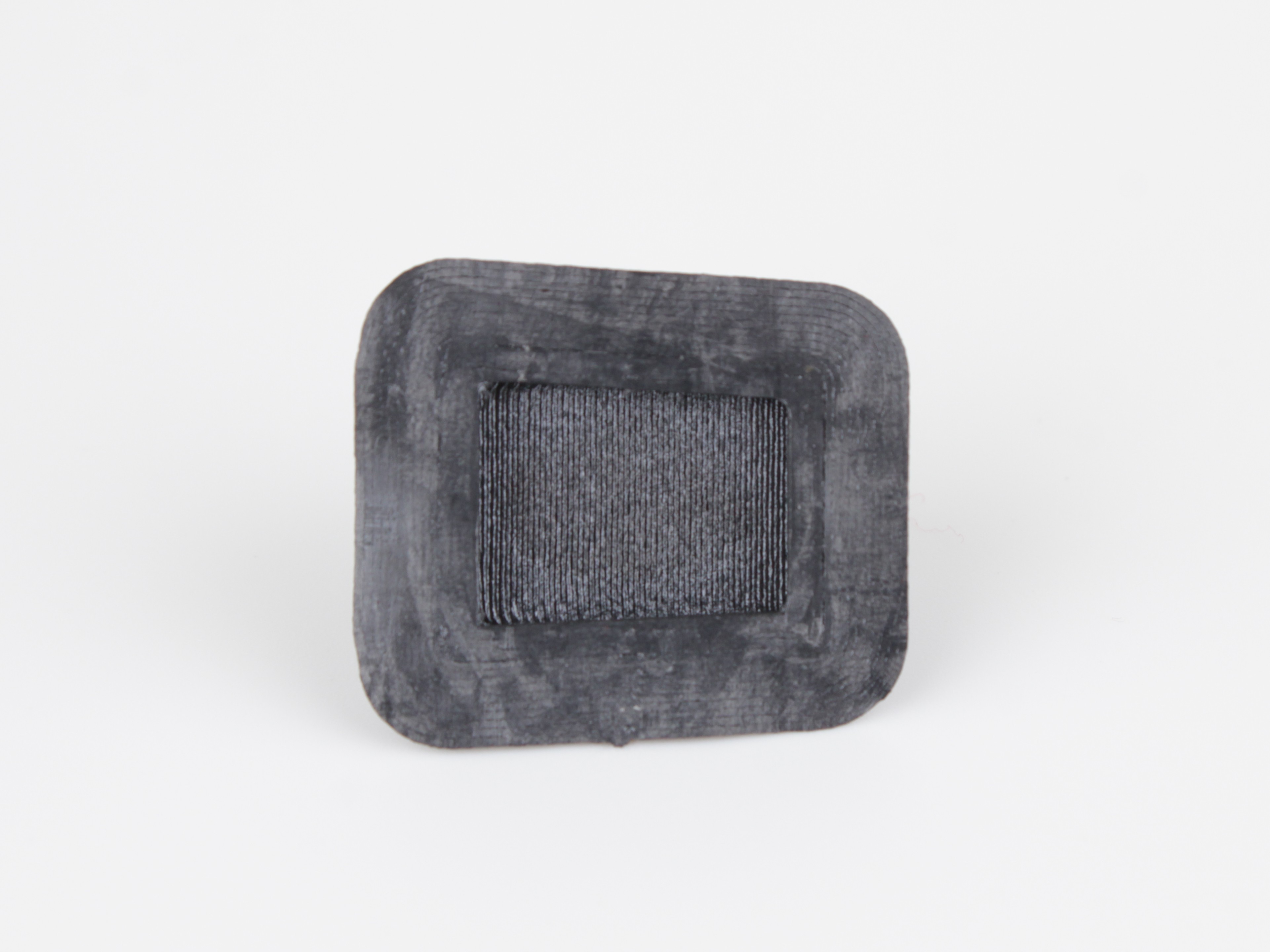
The result had no stringing and no sagging. Note how far these numbers sit from the profile defaults: the flow is well below 1.5 and the speed is a third of 30 mm/s. That is the pattern to take away. Slower and leaner beats faster and heavier when a bridge is giving you trouble.
Treat this as a starting point rather than a recipe. The right values depend heavily on which material you are printing, so test on the part you actually care about.
Dynamic Overhang and Fan Speeds
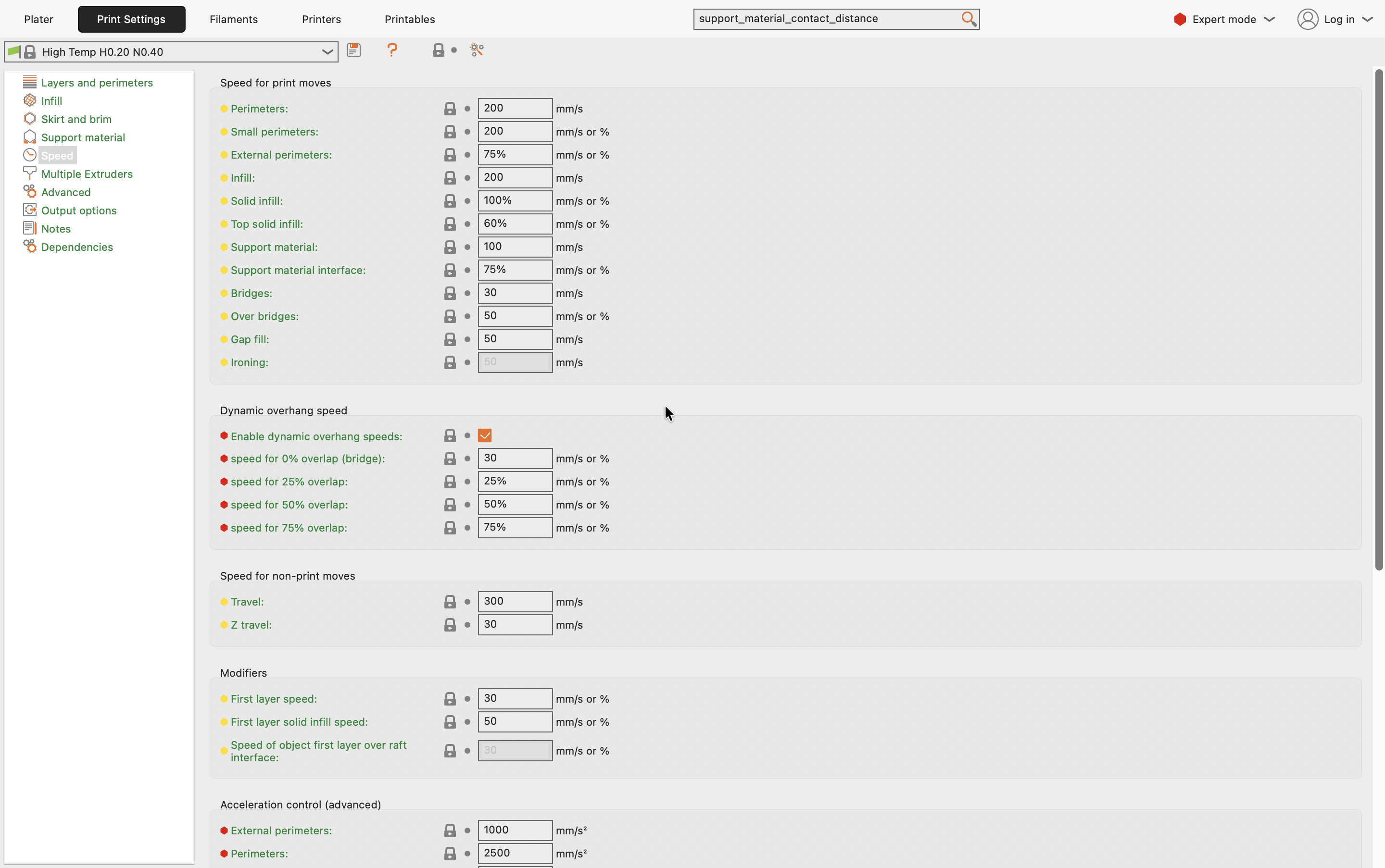
A bridge is simply an overhang with no material underneath it. PrusaSlicer can treat it as a special case: instead of applying one speed and one fan setting to the whole layer, it scales both according to how much of each extrusion is supported by the layer below. The 0% overlap row is the true bridge, where nothing supports the strand and it needs the slowest speed and the most cooling.
Both settings live in different tabs, and you tune them together.
Print Settings > Speed holds the bridging speeds. Bridges sets the base speed across a gap, and the Dynamic overhang speed section below it lets you set a separate speed for each overlap level:
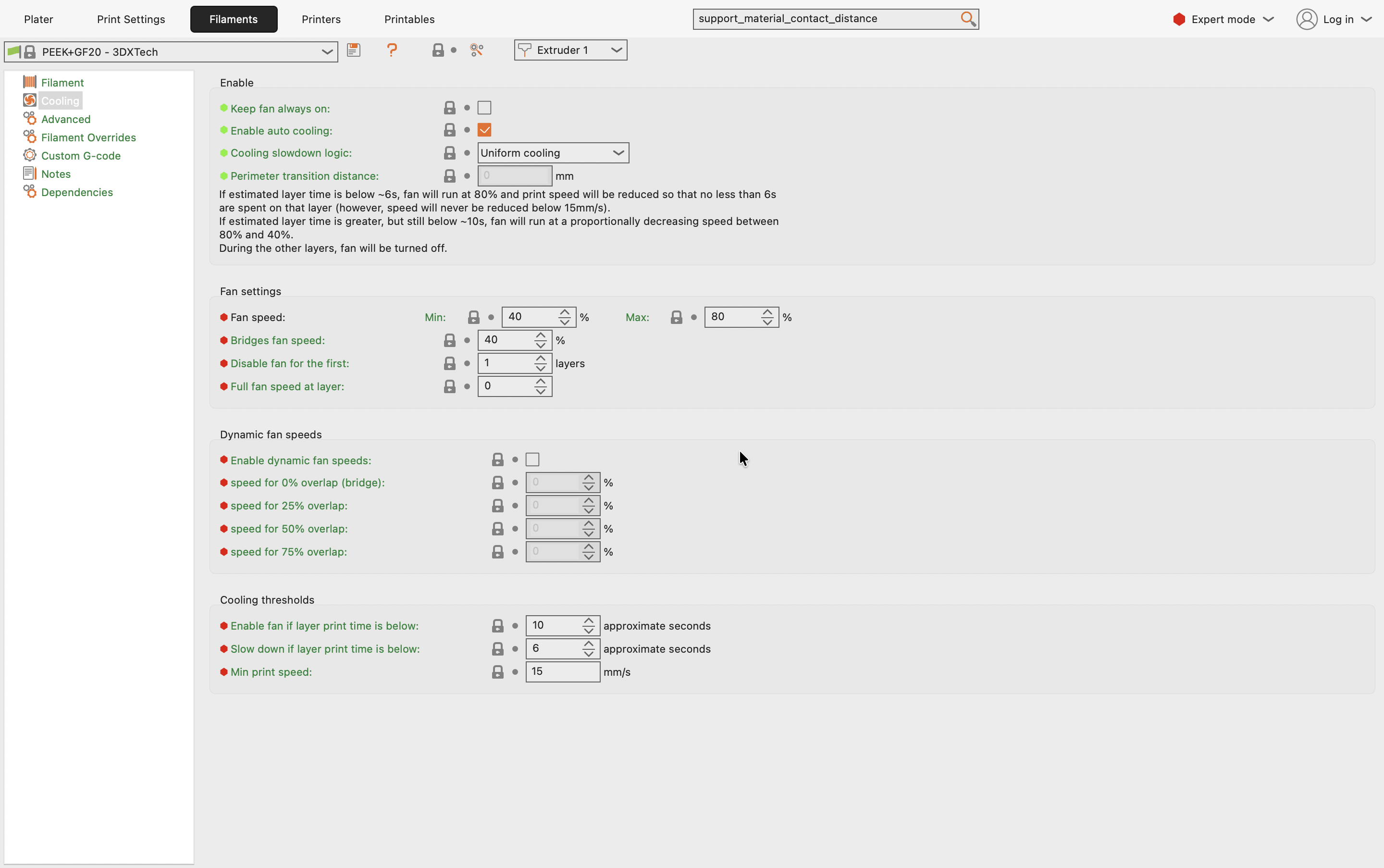
Filaments > Cooling holds the matching fan control. The Dynamic fan speeds section is switched off by default, so the fields stay greyed out and every overhang gets the same Bridges fan speed:
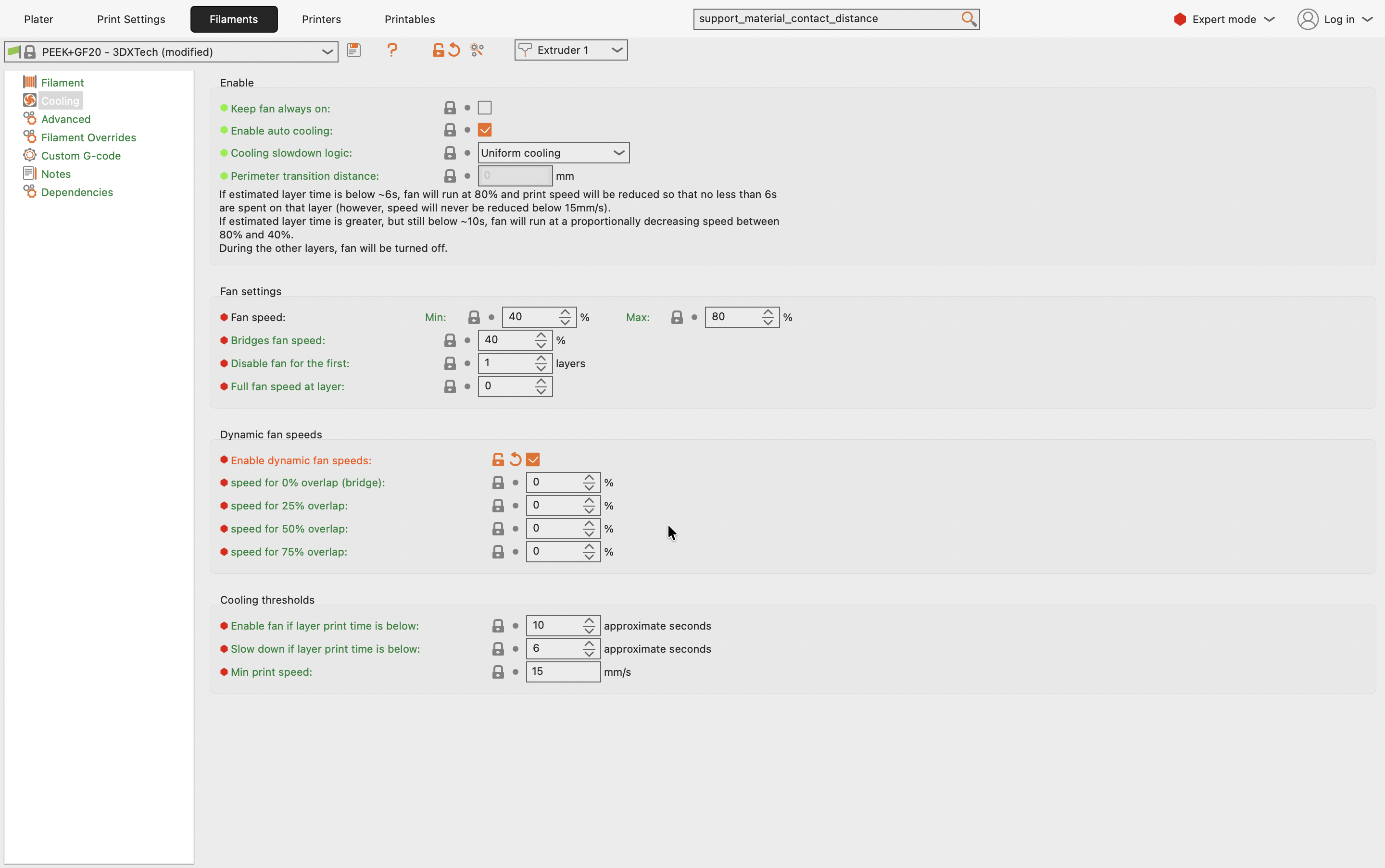
Tick Enable dynamic fan speeds and the per-overlap fields become editable. You can now raise the fan only for the least supported extrusions, giving bridges extra cooling without over-cooling the rest of the part:
Do not leave the per-overlap values at zero
Once Dynamic fan speeds is enabled, these per-overlap values replace the Bridges fan speed above. Leaving speed for 0% overlap (bridge) at 0%, as in the screenshot, means your bridges get no cooling at all, which is the opposite of what you want. Enable the section only if you are going to fill the values in.
Start from the stock values, change one overlap level at a time, and reprint the test model after each change until the bridges come out clean.
Testing and Calibration
The best way to dial in your settings is to use a dedicated calibration print. These models allow you to test bridges of varying lengths quickly.
- Download a Test Model: Search for "bridging test" on platforms like Printables or Thingiverse.
- Slice and Print: Use your baseline settings and print the test model.
- Analyze the Results: Observe which bridge lengths succeed and which fail. Look for sagging, clean lines, and solid surfaces.
- Adjust and Repeat: Tweak one setting at a time (e.g., lower the temperature by
5°C) and reprint the test. Repeat this process until you achieve clean bridges across the desired lengths.
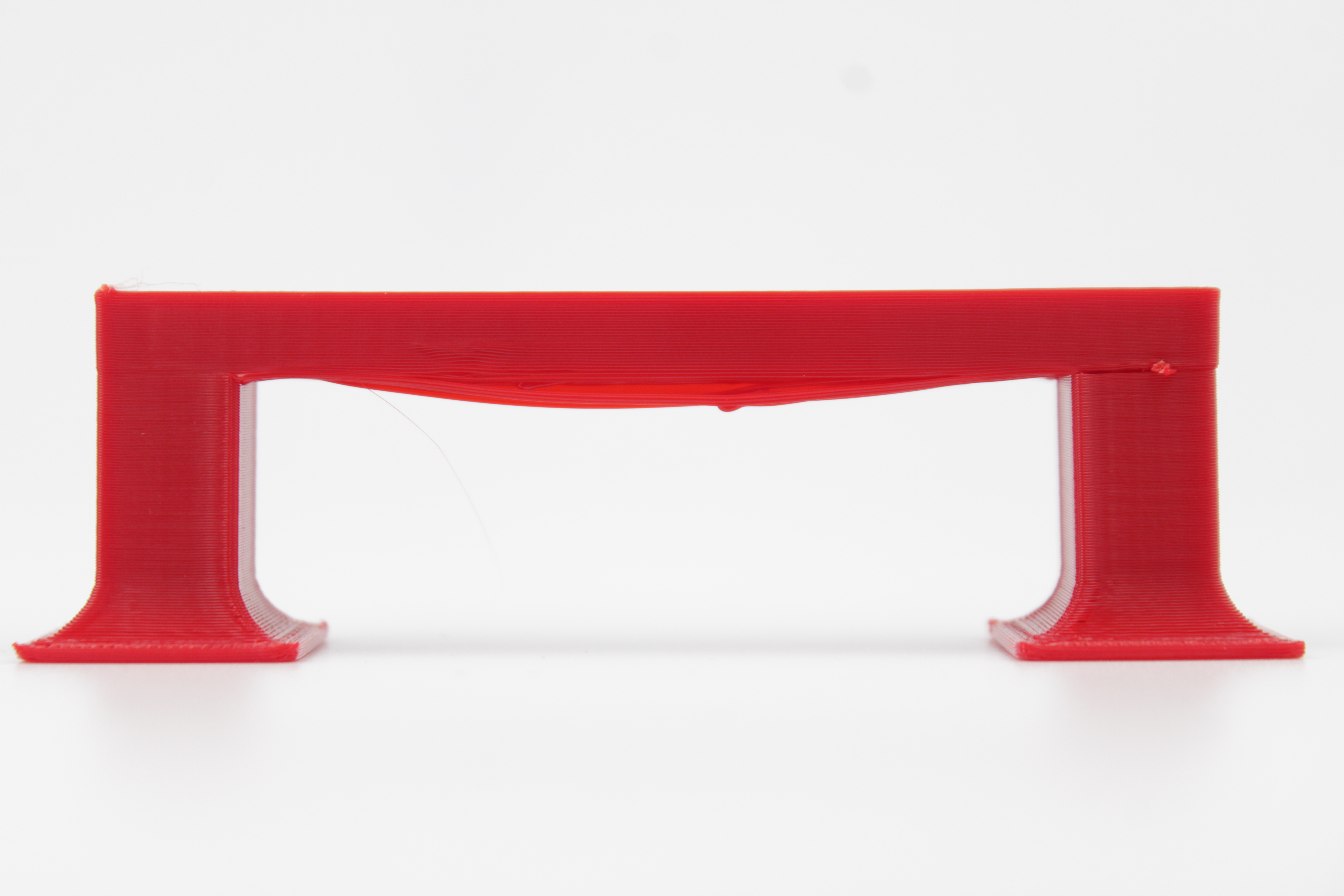
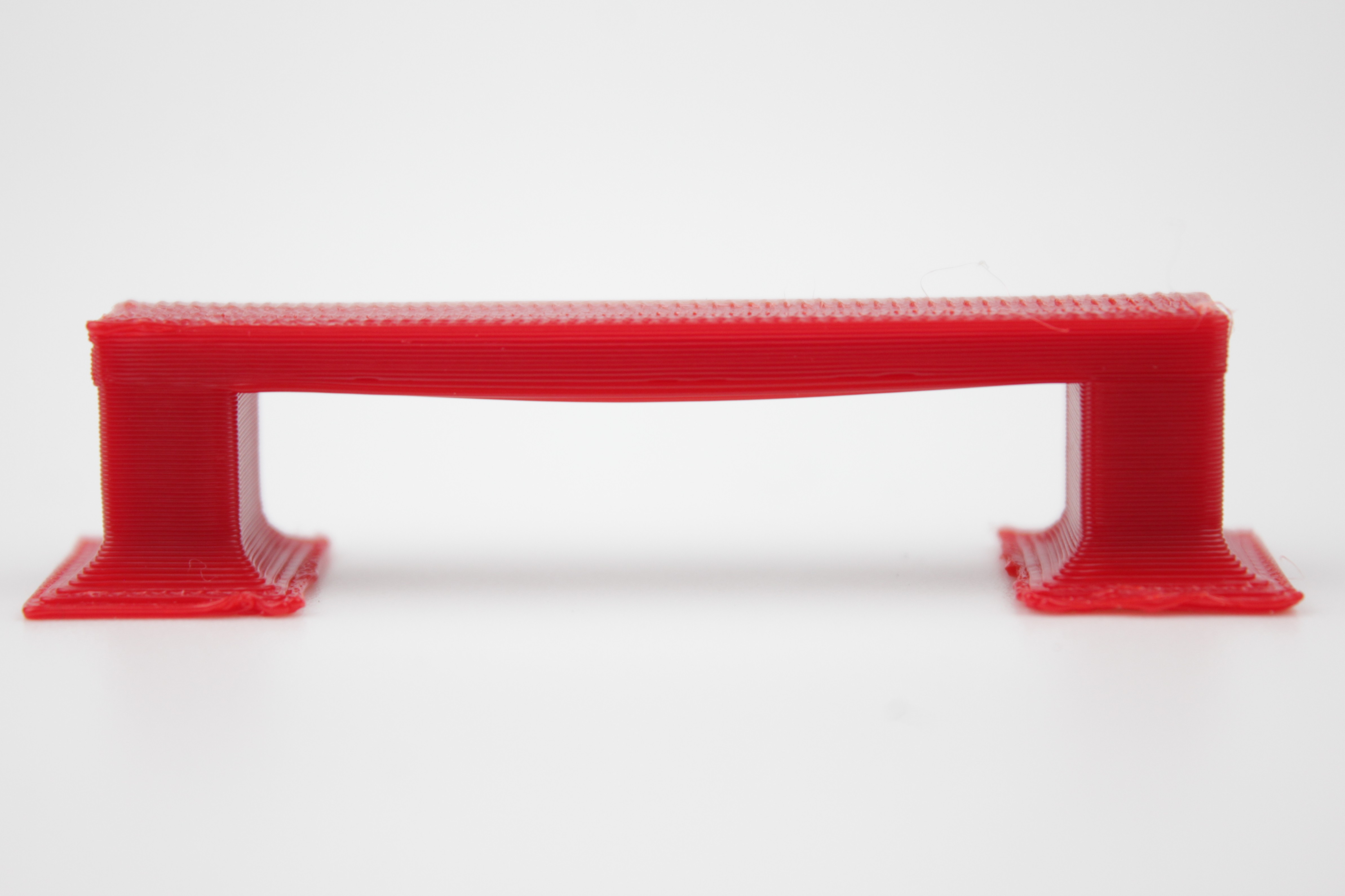
A single test print tells you little on its own. The value is in the comparison. Below, the same model printed before and after tuning:
FAQ
Support
If you could not find an answer here, reach out to our support team.