Infill vs Walls
Choose thicker walls over more infill for stronger parts — why 100% infill wastes time and invites warping, plus perimeter counts, density and patterns.
When aiming for maximum strength in 3D printed parts on your Vision Miner 22IDEX V4, a common instinct is to simply increase the infill percentage, perhaps even to 100%. However, understanding how different print settings contribute to structural integrity reveals a more nuanced and often more efficient approach: optimizing shell thickness (perimeters). This article clarifies the roles of infill and shells, addresses the myths around 100% infill, and explains why prioritizing shells is frequently the better strategy for strong, reliable parts.
YouTube media is off. Allow it in cookie settings to load this video.
Watch on YouTubeKey Questions Answered:
- Is 100% infill the strongest way to print?
- What's more effective for strength: More infill or thicker shells?
- Does 100% infill justify the extra print time and material?
- How do these settings affect warping, especially with engineering materials?
Understanding Strength: Shells vs. Infill
Shells (Perimeters/Walls): These are the outer outlines that form the visible surfaces of your print. Increasing the number of perimeters directly thickens the solid walls of the part.
Why They Matter: Basic engineering principles tell us that the material furthest from the center of an object contributes most to its resistance against bending forces - a common load type for functional parts. Shells inherently place material in these high-stress outer regions.
Efficiency: Research (like that conducted by CNC Kitchen) consistently shows that adding shells is significantly more material-efficient for increasing strength than adding infill. The filament orientation in shells is often aligned with typical stress directions, maximizing its contribution.
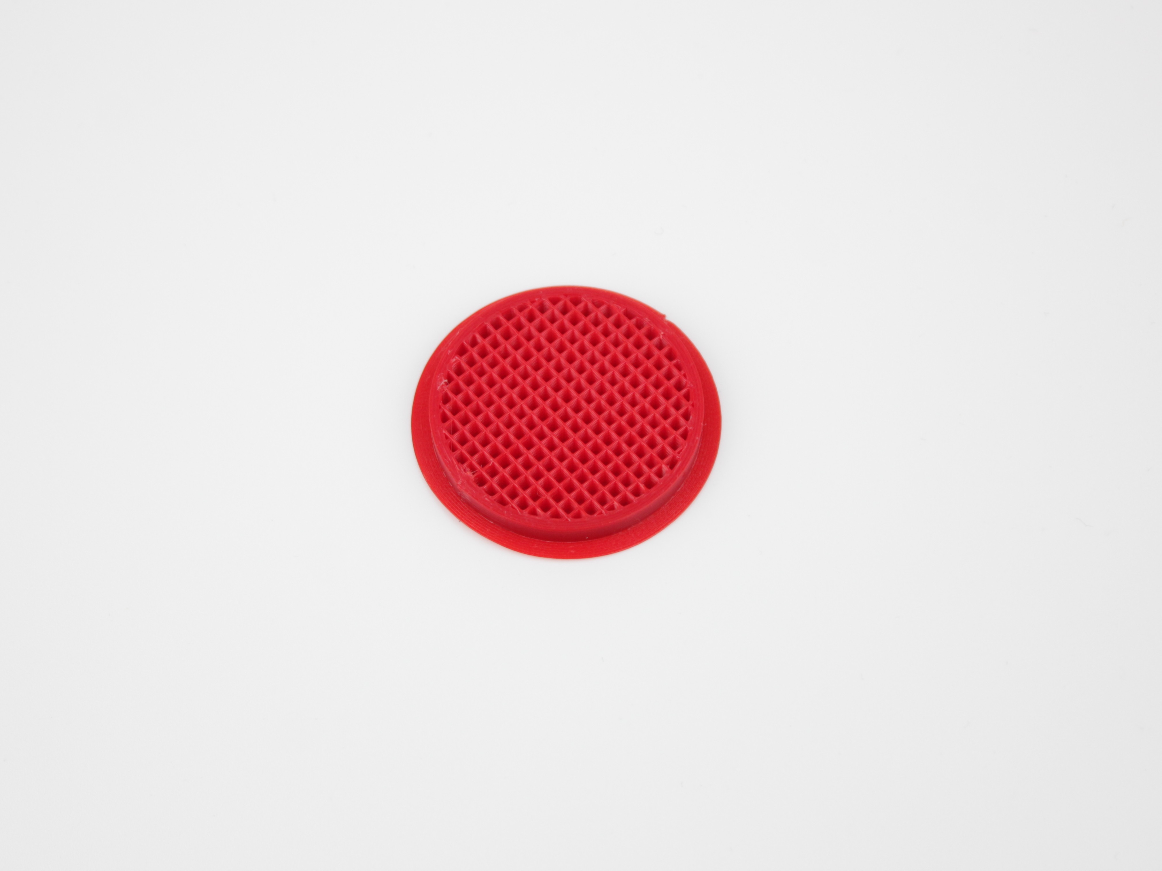
Infill: This is the internal support structure printed inside the shells. Its density and pattern influence the part's internal integrity, weight, and print time.
Role: Infill primarily provides internal support, helps connect opposing walls, supports top surfaces, and contributes some strength.
Diminishing Returns: While increasing infill density does add strength, the contribution diminishes as you move towards the core of the part. The material deep inside experiences much lower stress under most load conditions compared to the outer shells.
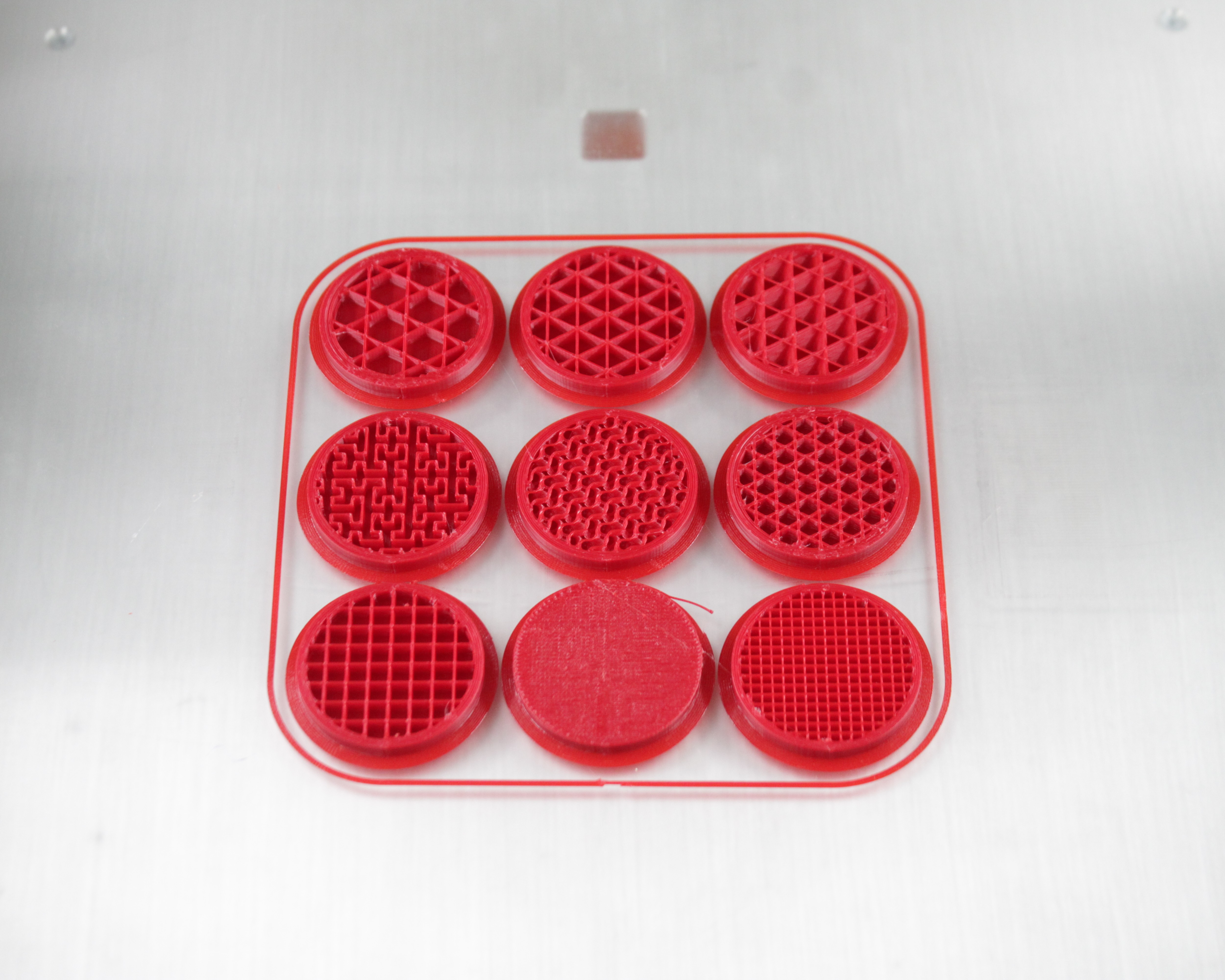
Every disc above uses the same model and the same material. Only the infill pattern, the density, and the perimeter count change:
| Position | Pattern | Density | Perimeters |
|---|---|---|---|
| Top left | Stars | 15% | 6 |
| Top centre | Triangles | 20% | 4 |
| Top right | Cubic | 20% | 4 |
| Middle left | Hilbert curve | 20% | 4 |
| Middle centre | Gyroid | 20% | 4 |
| Middle right | Stars | 30% | 5 |
| Bottom left | Rectilinear | 20% | 3 |
| Bottom centre | Rectilinear | 100% | 0 |
| Bottom right | Grid | 20% | 4 |
A few things are easier to see once you know what you are looking at:
- The solid disc, bottom centre, is 100% infill with no perimeters at all, which is why it has no wall around its edge. Compare it with the 15% and 30% Stars discs to judge how much extra material 100% costs for the strength it buys.
- Grid and Rectilinear look different at the same 20% density. Grid lays both directions in every layer, so from above you see a full mesh and it reads as denser (bottom right). Rectilinear alternates direction layer by layer, so you mostly see the top layer and it reads as more open (bottom left).
- The wall thickness around each disc is the perimeter count. The 15% Stars disc has the thickest ring of all at 6 perimeters, even though its infill is the sparsest. That is the whole point of this article: walls, not infill, are where strength comes from.
The Myth of 100% Infill
Many users assume printing solid (100% infill) yields the absolute strongest part. While it uses the most material, it's often not the most practical or even the most effective approach:
-
Inefficiency: As mentioned, much of that internal material contributes little to strength under typical loads (like bending). You spend significantly more time and material for marginal gains compared to adding shells.
- Example: CNC Kitchen found a part with 6 shells and 15% infill was as strong as one with 2 shells and 100% infill, but likely printed faster and used less material overall.
-
Print Time & Cost: Printing at 100% infill drastically increases print time and material consumption.
-
Potential Quality Issues: Achieving a truly void-free 100% infill is difficult. Even slight over-extrusion can accumulate within a solid part, potentially causing dimensional inaccuracies, surface defects, or even nozzle jams.
-
Increased Warping Risk (Especially with PEEK/ULTEM): This is critical for Vision Miner users printing high-temperature materials. Large, solid cross-sections build up significant internal stress as they cool. Printing at 100% infill dramatically increases the part's thermal mass and internal stresses, making it much more prone to warping and detachment from the build plate compared to a part with thick shells and moderate infill.
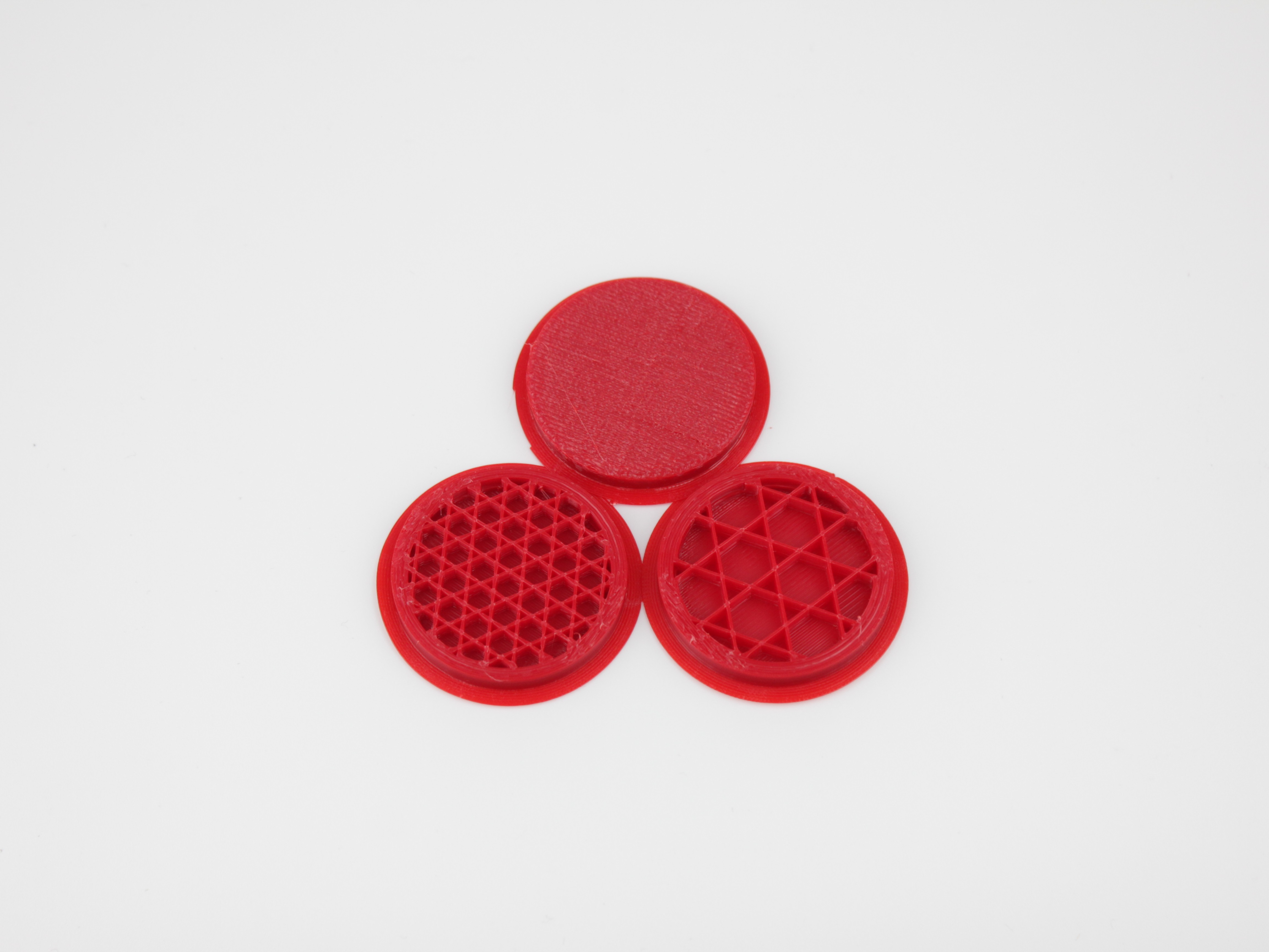
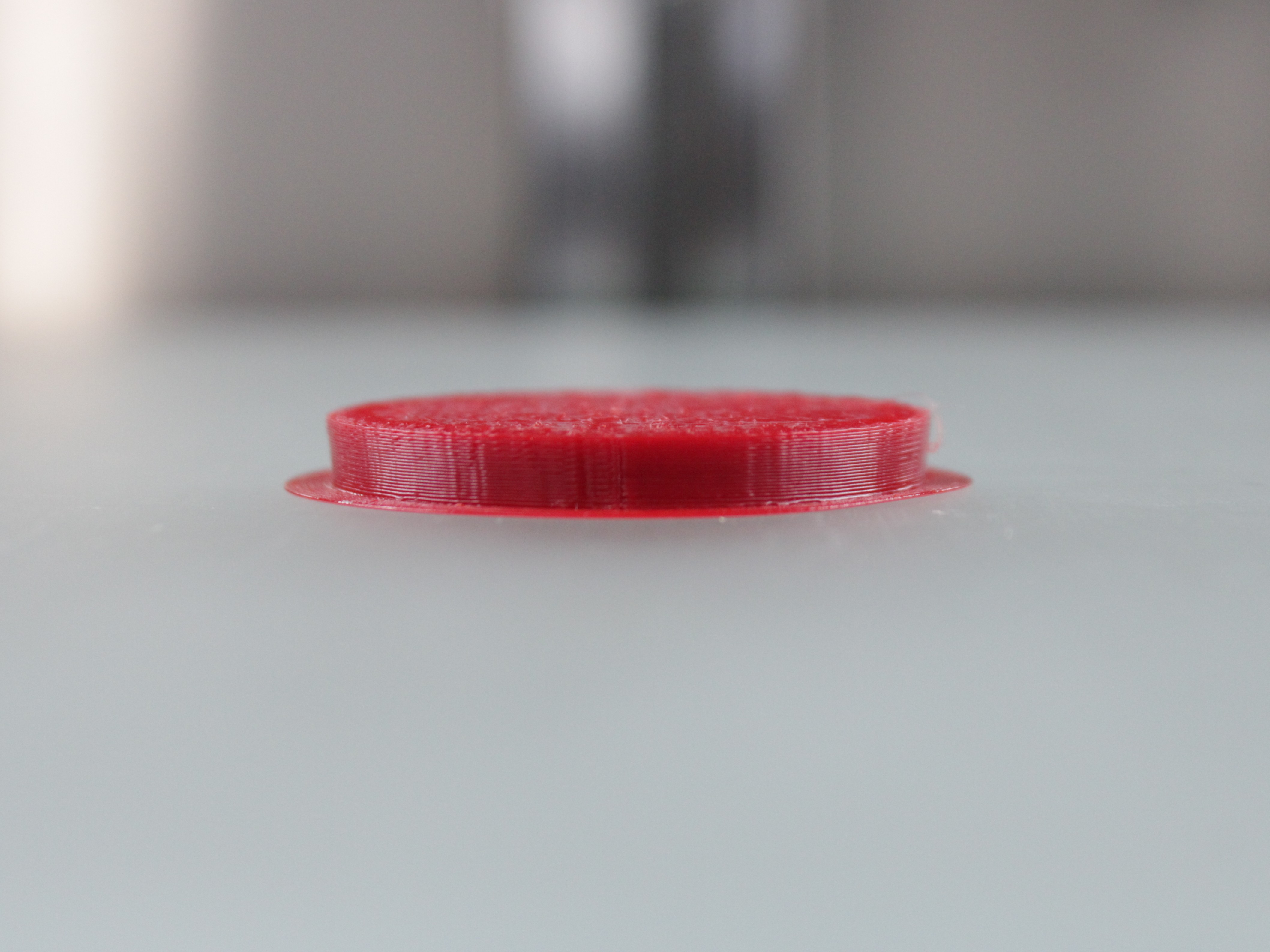
100% infill increases print failure risk
While technically the densest, 100% infill is often an inefficient use of material and time, and significantly increases the risk of print failures like warping, especially with engineering-grade materials.
Recommended Strategy for Strong Parts
For optimal strength, efficiency, and reliability on your Vision Miner 22IDEX V4:
-
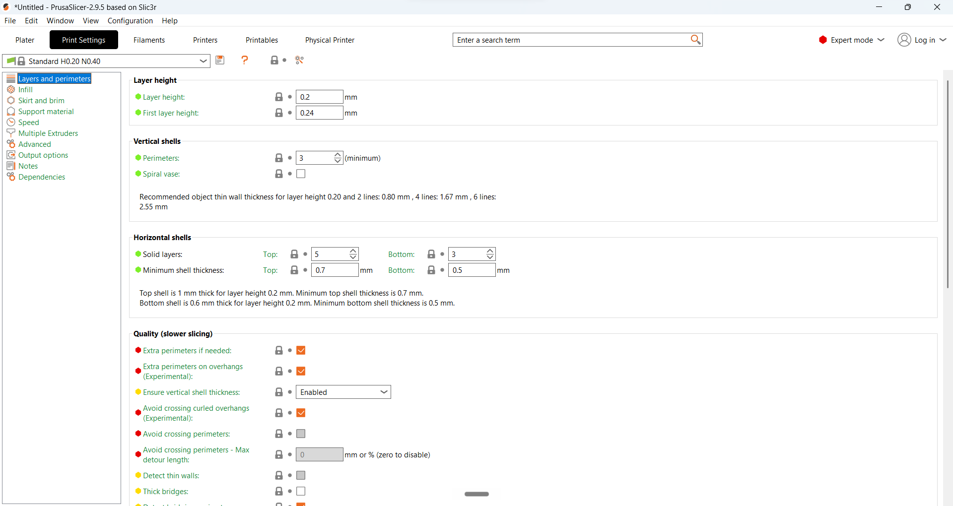
Prioritize Shells: Increase the number of Perimeters (or Wall Lines) in your slicer settings first. For functional parts, 3 to 6 perimeters is often a good range.
-
Increase Top/Bottom Layers: Ensure sufficient Top/Bottom Solid Layers to match the wall thickness created by your perimeters.
-
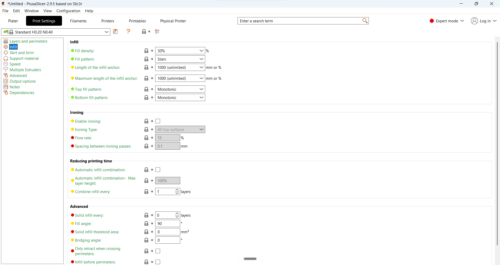
Use Moderate Infill: Select a reasonable Infill Density, typically between 15% and 50%. This provides internal support without excessive material use or print time.
-
Choose a Suitable Infill Pattern: Patterns like Grid, Gyroid, or Triangles generally offer good strength and support. Rectilinear (lines) prints faster.
This approach focuses material where it counts most (the outer walls), reduces print time and material use compared to 100% infill, and crucially, helps mitigate warping by reducing the solid mass and internal stresses within the part.
Try it yourself
Reading about patterns only gets you so far. The nine test discs shown above are available as a ready-to-slice PrusaSlicer project, with the pattern, density, and perimeter count already set per disc. Print it in the material you actually use, then break the discs by hand and pick the combination you trust.
| File | Format |
|---|---|
Infill vs walls test project (TODO: upload Infill_vs_walls.3mf to R2 and link it here) | .3mf |
FAQ
Support
If you could not find an answer here, reach out to our support team.