Part Placement
Place parts correctly for each print mode: T0, T1, Duplicate, Mirror and dual-material zones, dock-zone limits, Y-axis orientation and mid-air print fixes.
The Vision Miner 22IDEX V4 has a heated aluminum build plate. Where you place your model depends on the printing mode: each mode has a different usable print area. Getting placement wrong can cause failed prints, collisions, or printing outside the reachable area.
Printing Modes
The printer supports five printing modes:
- T0 only: printing with the left extruder
- T1 only: printing with the right extruder
- Duplicate Mode: both extruders print identical copies simultaneously
- Mirror Mode: both extruders print mirrored copies simultaneously
- Dual-color / dual-material: both extruders work on a single part (e.g., two colors or soluble support)
Bed directions
As you face the printer, the Y-axis runs along the bed, front to back (lengthwise). The X-axis runs across the bed, left to right. So "orient along the Y-axis" just means turn the part lengthwise, front-to-back.
1. T0 (Left Extruder) Only
- Select T0 as the active extruder in your slicer.
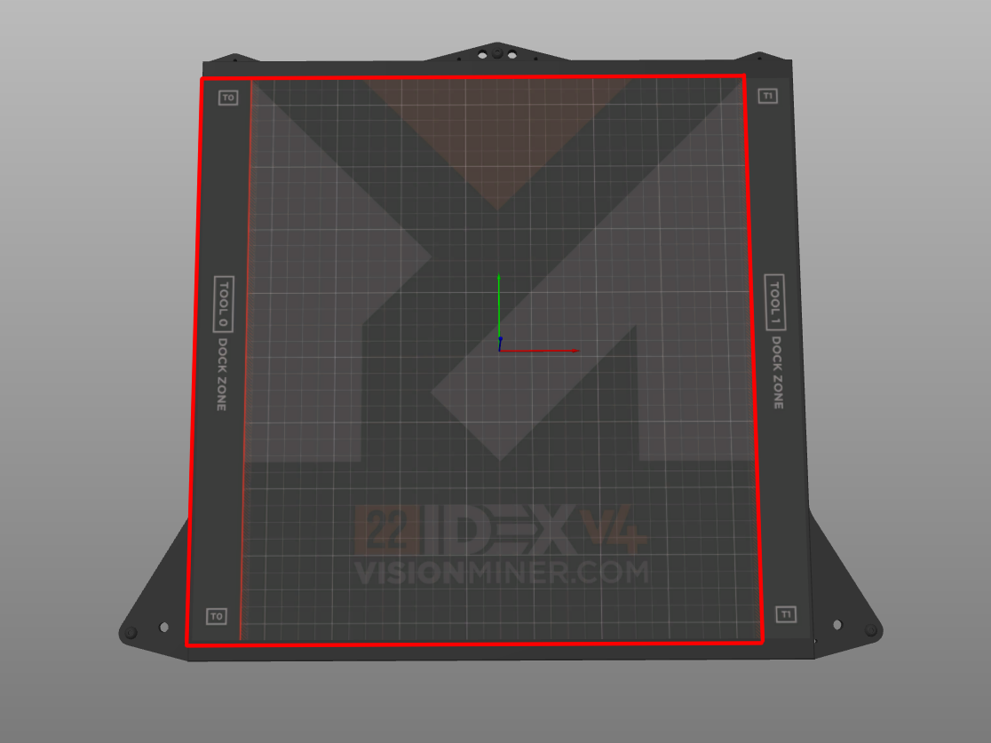
- Place your model inside the outlined zone shown below. T0 reaches almost the whole bed.
- Keep parts clear of the far right of the bed, where T1 docks. T0 cannot reach it.
- Even though T0 reaches almost the whole bed, position your parts near the center when you can, whether you have a few or many. Parts printed toward the middle come out with better quality than those pushed out to the edges.
2. T1 (Right Extruder) Only
- Select T1 as the active extruder in your slicer.
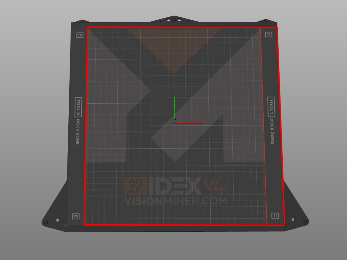
- Place your model inside the outlined zone shown below. T1 reaches almost the whole bed.
- Keep parts clear of the far left of the bed, where T0 docks. T1 cannot reach it.
- Even though T1 reaches almost the whole bed, position your parts near the center when you can, whether you have a few or many. Parts printed toward the middle come out with better quality than those pushed out to the edges.
Use a raft in Mirror and Duplicate modes
Use a raft by default in both modes. In PrusaSlicer, turn one on under Print settings > Support material > Raft layers; set at least 3 layers in Duplicate Mode. You can try without one only for a single part with a large, flat footprint, and only if you are ready to watch the first layer closely. Automatic bed leveling compensation (height map) is disabled in Duplicate Mode, so first layer adhesion there depends entirely on manual bed leveling and the raft.
3. Duplicate Mode
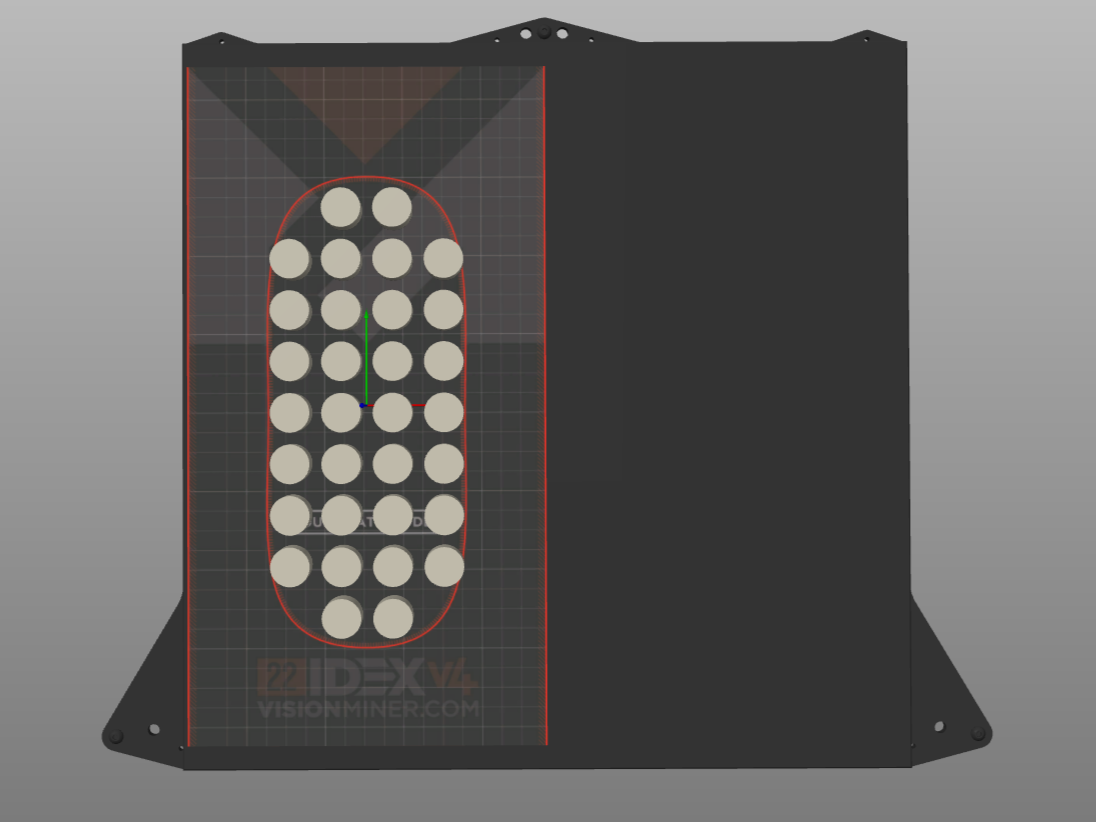
Duplicate Mode prints two identical copies: T0 prints the original on the left half, T1 prints the duplicate on the right half. When you select this mode in the slicer, the available print area is automatically limited to the left half of the build plate.
- Place your part within the recommended zone shown below.
- Orient the part so the longest dimension runs along the Y-axis (front-to-back). Minimize the X-axis dimension.
- Turn on a raft with at least 3 layers (see the note above). Use one for every Duplicate Mode print unless the part is single and has a large, flat footprint.
Height map disabled in Duplicate Mode
Height map (automatic bed leveling compensation) is disabled in Duplicate Mode. Print small parts to minimize the effect of any bed unevenness. The 3-layer raft compensates for minor leveling differences.
4. Mirror Mode
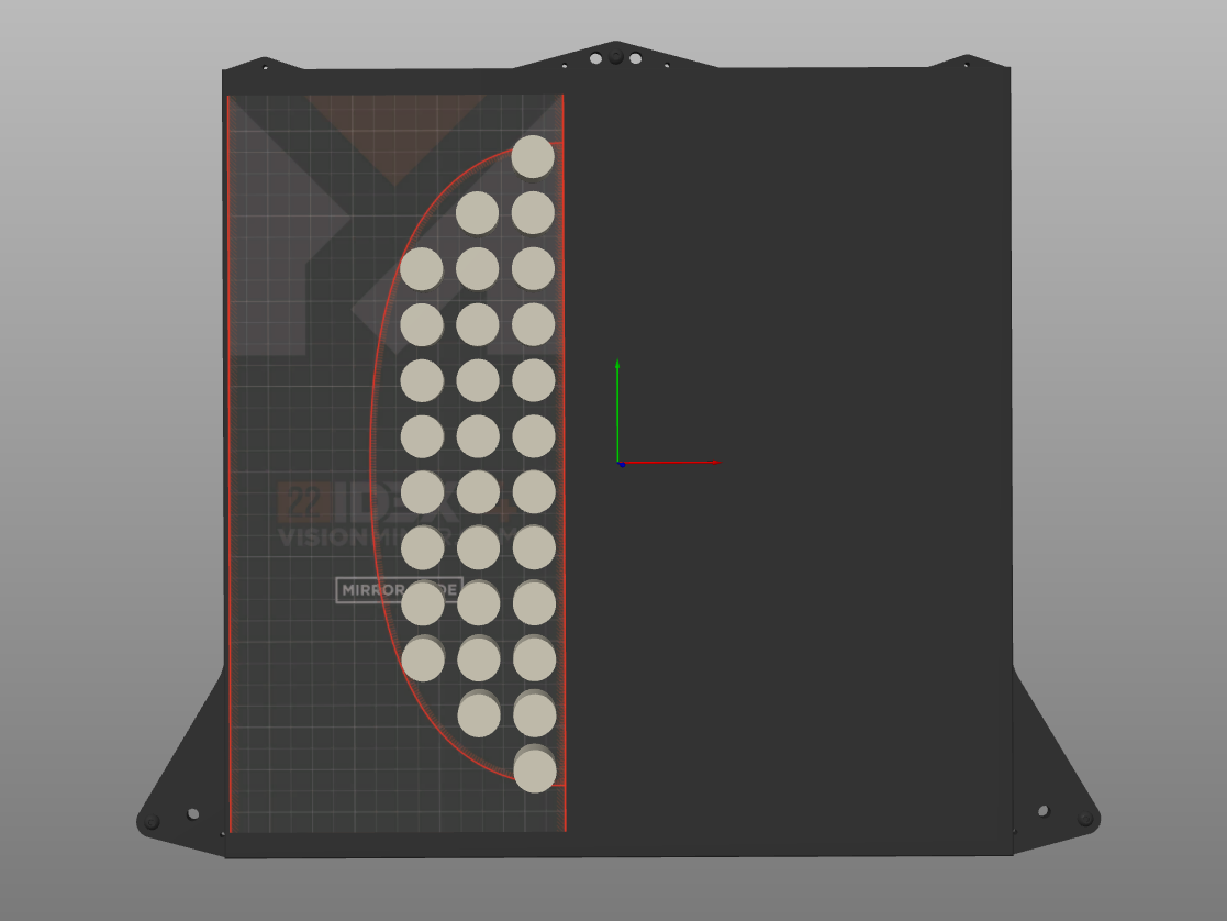
Mirror Mode prints a symmetrical (mirrored) copy of your part. One extruder prints the original, the other prints the reflection. When you select this mode in the slicer, the available print area is automatically limited to half the build plate.
- Place your part within the recommended zone shown below, as close to the bed's center line as possible. The two mirrored copies then print near each other, which keeps any small alignment errors to a minimum.
- Orient the part so the longest dimension runs along the Y-axis (front-to-back). Parts pushed out toward the left edge are more prone to slight misalignment.
- Turn on a raft (see the note above). Use one for every Mirror Mode print unless the part is single and has a large, flat footprint.
5. Dual-Color / Dual-Material Printing
When using both extruders on a single part (two colors, two materials, or soluble support), the T0 and T1 print zones overlap. The usable print area is almost identical to single-extruder mode: the only limitation is a few centimeters on each side where the extruder dock zones are located.
Each tool is locked out of the opposite dock zone
T0 cannot reach the far right of the bed, where T1 docks, and T1 cannot reach the far left, where T0 docks. Everything between those two strips is reachable by both. If a part crosses into the opposite dock zone, the print will fail.
Always check slicer preview
After placing and configuring your parts in any mode, always check the slicer Preview. Verify that toolpaths stay within the expected boundaries for your selected mode and extruder(s).
FAQ
Troubleshooting
Support
If you could not find an answer here, reach out to our support team.