Temperature Sensors
Replace the bed, chamber heater or chamber air temperature sensor on the 22 IDEX V3 — pulling the new wire along the old, thermal paste and a heat test.
This guide covers replacing three temperature sensors on the Vision Miner 22 IDEX: the Bed Temperature Sensor, the Chamber Heater Temperature Sensor, and the Chamber Temperature Sensors. Accurate sensors are essential for temperature control, print quality, and safe operation.
Replacing a faulty sensor restores accurate temperature monitoring and prevents print failures or thermal faults. Before starting, make sure you have the correct replacement sensor for the job.
The Head Temperature Sensor is a separate procedure, covered in Hotend Temp Sensor & Heater Maintenance.
Before you begin - safety and risk
Read the Safety - Before You Begin article to understand the hazards involved in working on the Vision Miner 22 IDEX printer – including electrical, thermal, mechanical, and chemical risks. All procedures in this wiki are provided as recommendations only. By choosing to follow any procedure, you do so at your own risk.
Tools & Materials
- Replacement Bed Temperature Sensor
- Replacement Chamber Heater Temperature Sensor
- Replacement Chamber Temperature Sensors
- 2 mm Hex Driver
- 5.5 mm Wrench (or pliers)
- PH2 Phillips Screwdriver
- Small Hammer
- Drift Punch Tool (approx. 6 mm diameter, or a similar sturdy rod)
- Wire Cutters (flush cutters)
- Tweezers (fine tip)
- Electrical Tape
- Boron Nitride Paste (thermal paste)
- Zip Ties (small)
- Chamber Temp Sensor Holder – printed holders, optional but recommended (download STL)
1. Bed Temperature Sensor
The bed temperature sensor sits underneath the print bed and monitors the bed surface temperature, which is critical for print adhesion.
Power off and let the bed cool
Power off the printer and unplug the power cord before starting. Let the print bed cool completely to room temperature to avoid burns.
Access the Sensor
- Unscrew Bed Screws: Using a 5.5 mm Wrench and 2 mm Hex Driver, unscrew the front left bed mounting screw and the rear center bed mounting screw.
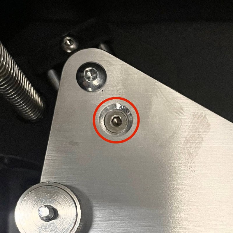
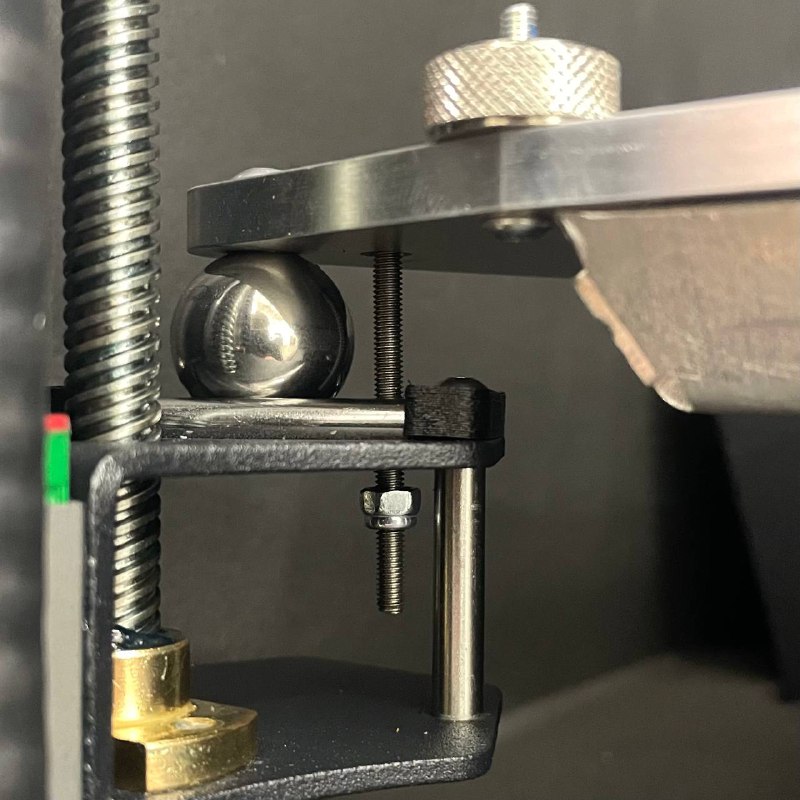
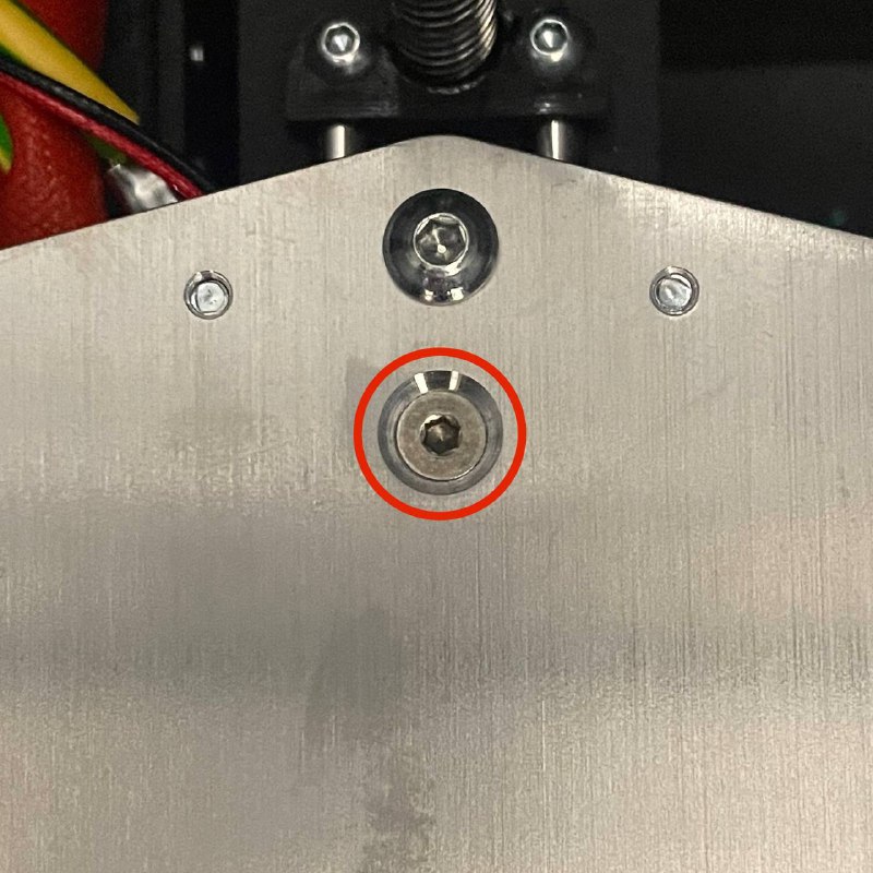
- Remove Rear Left Bed Holding Nut: Completely unscrew and remove the nut securing the rear left corner of the build plate.
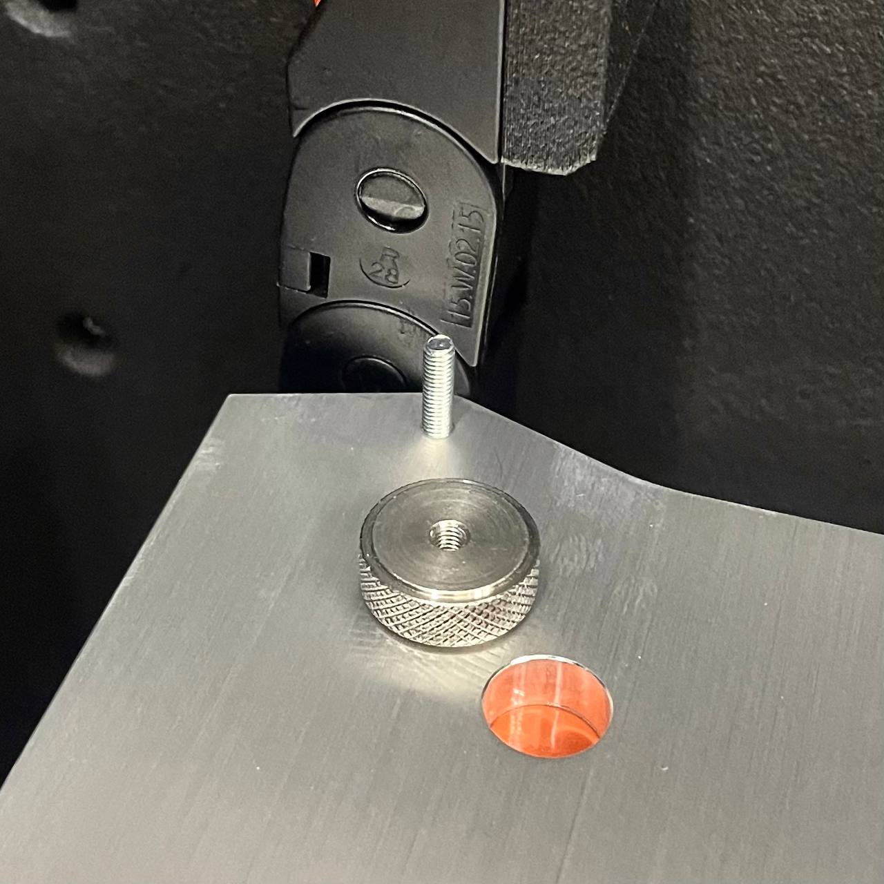
- Displace the Bed: Carefully lift the left side of the bed slightly and slide the entire bed assembly towards the right and slightly forward to reach the sensor mounting location underneath. Be careful not to strain any wires.
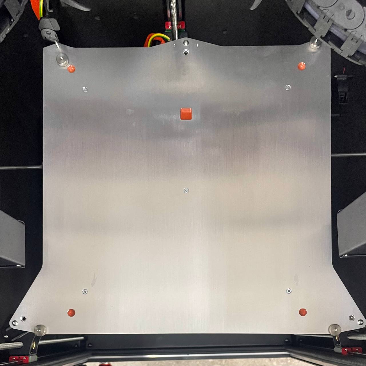
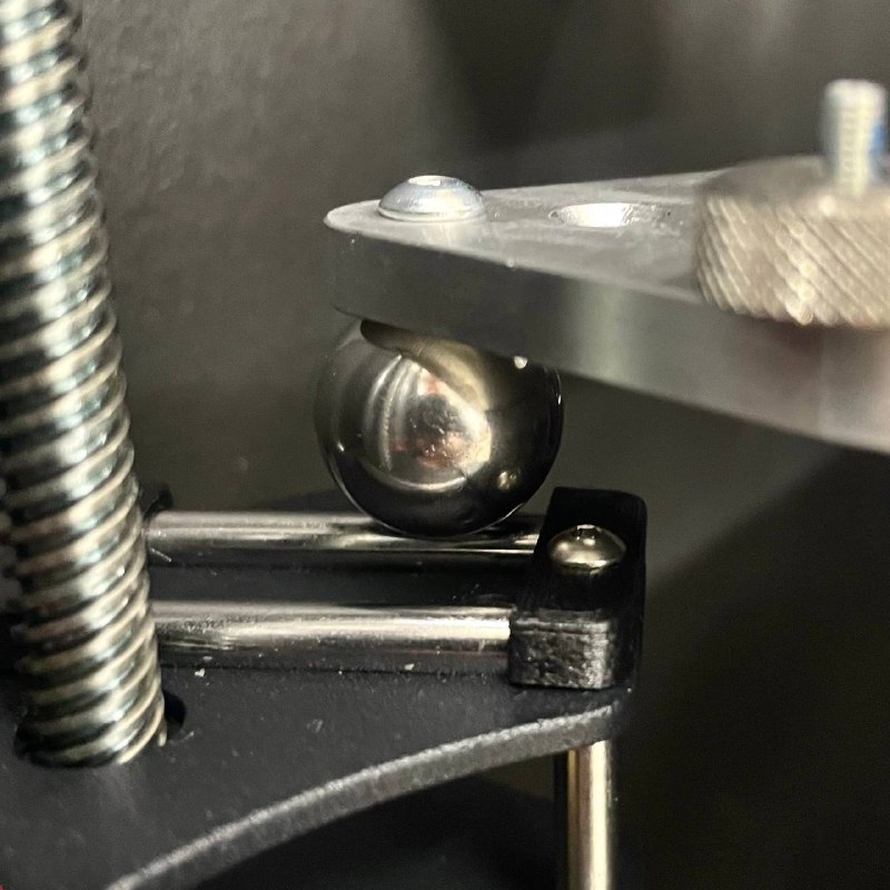
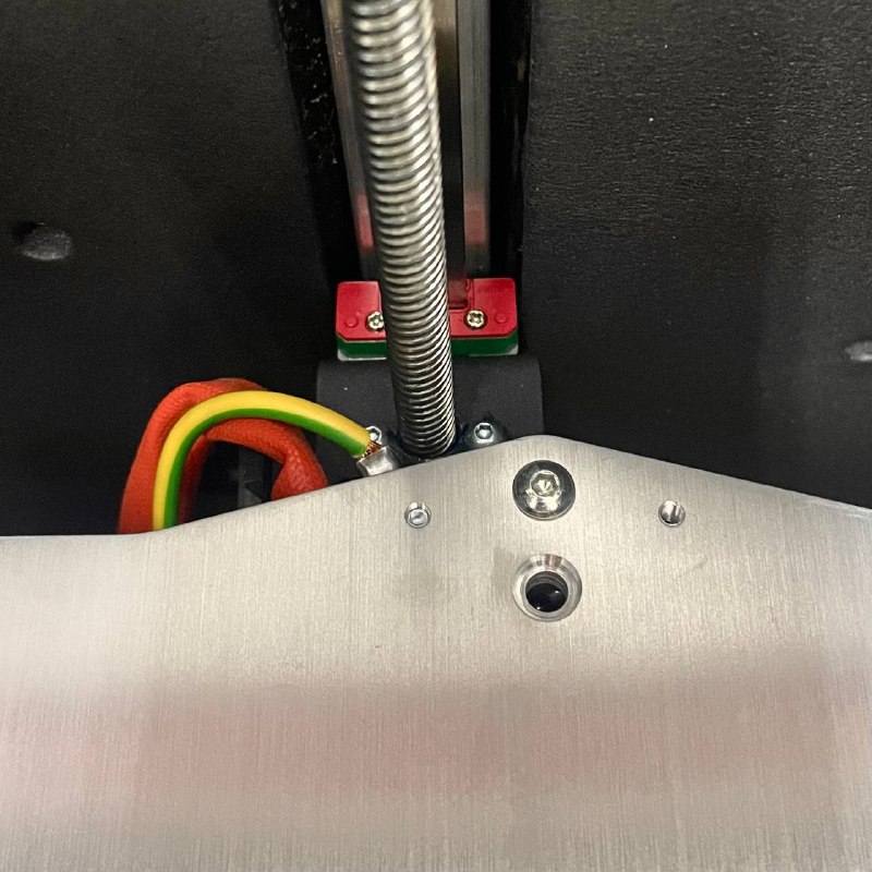
- Unscrew Sensor: Locate the bed temperature sensor secured underneath the bed plate. Use a 2 mm Hex Driver to remove the screw holding it in place. Set the screw aside.
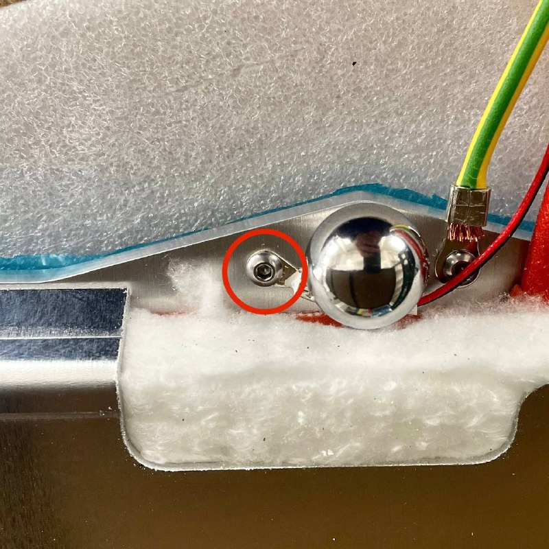
Route and Replace the Sensor
- Access Wiring: Open the rear access doors of the printer.
- Cut Zip Ties: Locate the bed temperature sensor cable within the wiring loom. Using Wire Cutters, snip the zip ties securing the sensor cable. Be careful not to cut any other wires.
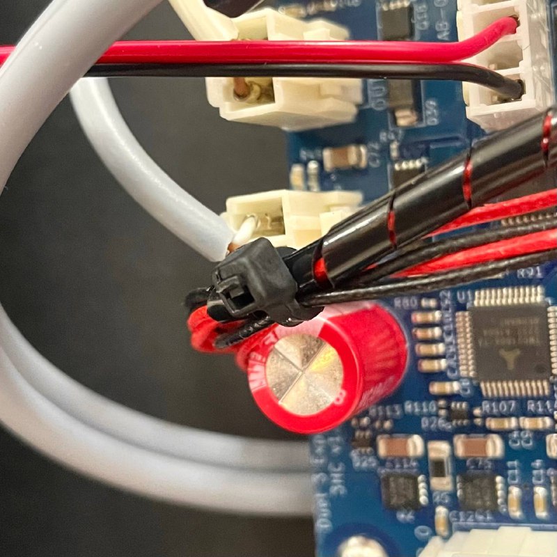
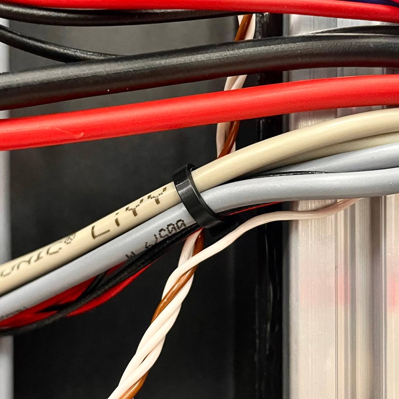
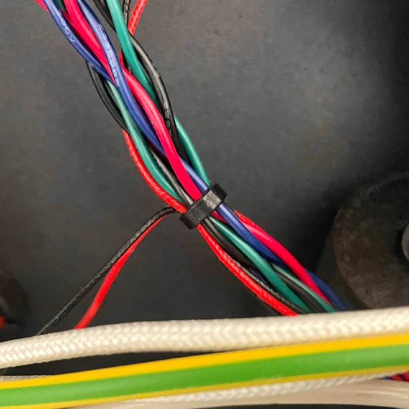
- Disconnect Sensor: Trace the sensor cable to the mainboard. Identify the bed temperature sensor connector (refer to the Wiring Schematic if unsure) and unplug it from the board.
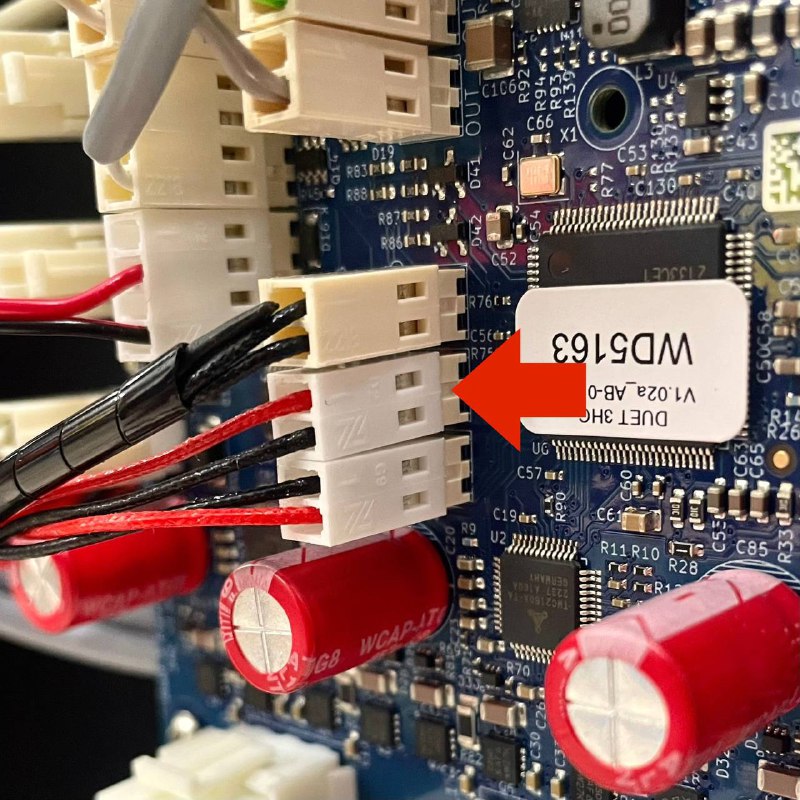
- Attach New Sensor: Cut off the connector from the old sensor, firmly tie the wires to the end of the new sensor (the sensor end), and wrap the connection with tape. The connection must be smooth and strong enough to pull through the cable channels without snagging or separating.
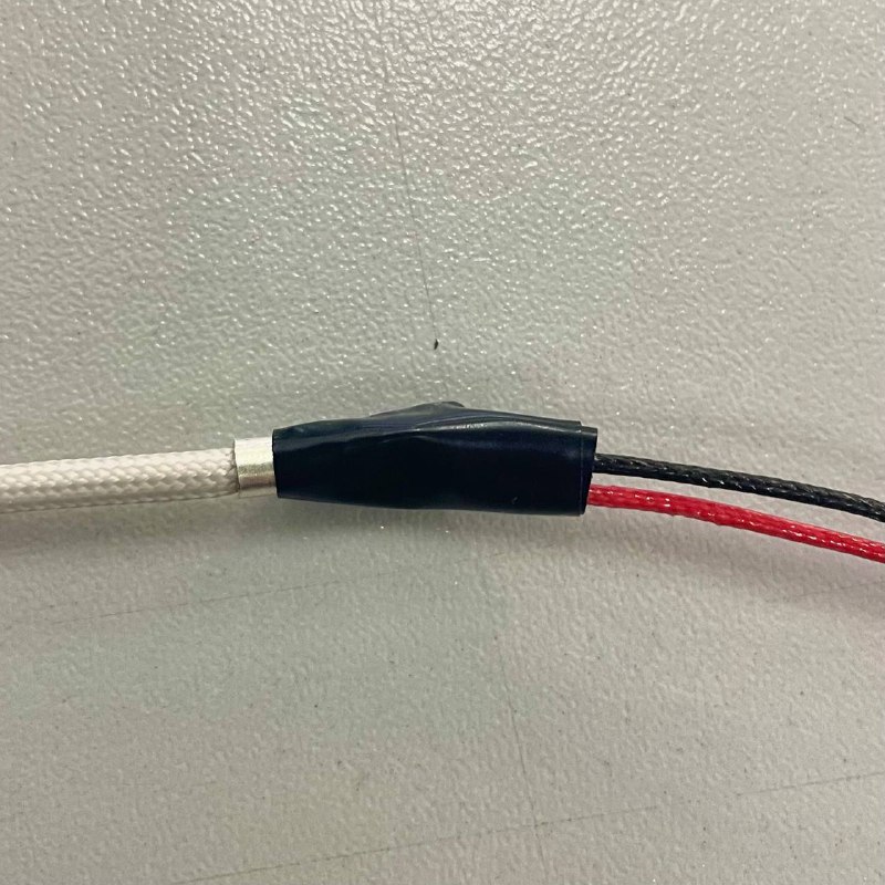
- Pull New Sensor Wire: Gently pull the old sensor wire out, guiding the new sensor wire along the same path through the rear compartment to the bed plate. Pull slowly and steadily. If you feel resistance, check for snags – removing cable channel covers temporarily can help.
Avoid excessive force on the new wire
Pulling too hard can damage the new sensor's wiring. If it snags, back off and clear the path rather than forcing it.
- Disconnect Old Sensor: Once the new sensor wire is fully routed, remove the tape and separate the old sensor from the new one.
- Connect New Sensor: Plug the new connector into the correct socket on the mainboard.
Reassembly and Testing
- Apply Thermal Paste: Apply a small amount of Thermal Paste to the metal casing of the new sensor head for good thermal contact with the bed plate.
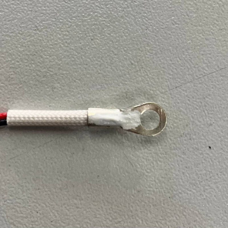
- Mount Sensor: Position the new sensor into its mounting location under the bed plate and secure it with the 2 mm Hex Driver and the screw removed earlier. Do not overtighten.
- Position Bed: Slide the bed assembly back to its original position.
- Secure Bed: Reinstall the rear left bed nut using pliers or a wrench, then screw the front left and rear center adjustment screws using the 5.5 mm Wrench and 2 mm Hex Driver.
- Secure Wiring: In the rear compartment, route the new sensor cable alongside the other wiring and secure it with new Zip Ties. Make sure cables are not pinched or strained.
- Final Checks: Close the rear access doors and plug the power cord back in.
- Test Sensor: Power on the printer. In the Web Interface, start heating the bed (for example to
60°C) and confirm the reading rises steadily toward the target.
Bed leveling required after this procedure
Moving the bed changes its position. Run a full bed leveling before your next print.
2. Chamber Heater Temperature Sensor
This sensor monitors the chamber heater element, ensuring the build chamber reaches and holds the target temperature.
Let the chamber heater cool completely
Power off and unplug the printer, and allow the chamber heater element and surrounding areas to cool fully. The heater reaches high temperatures.
Access the Sensor
- Position Printer for Access: Position the printer to reach the screws underneath the chamber heater assembly, at the left rear of the build chamber. Either place it on a raised stand or blocks, or slide it partially off a sturdy table edge so it rests stably on three feet with clearance underneath.
Keep the printer stable before working underneath
Make sure the printer cannot tip over before reaching under the chamber heater assembly.
- Unscrew Heater Assembly: Using a PH2 Phillips Screwdriver, unscrew the mounting screws securing the chamber heater assembly to the printer frame for better access to the sensor screw.
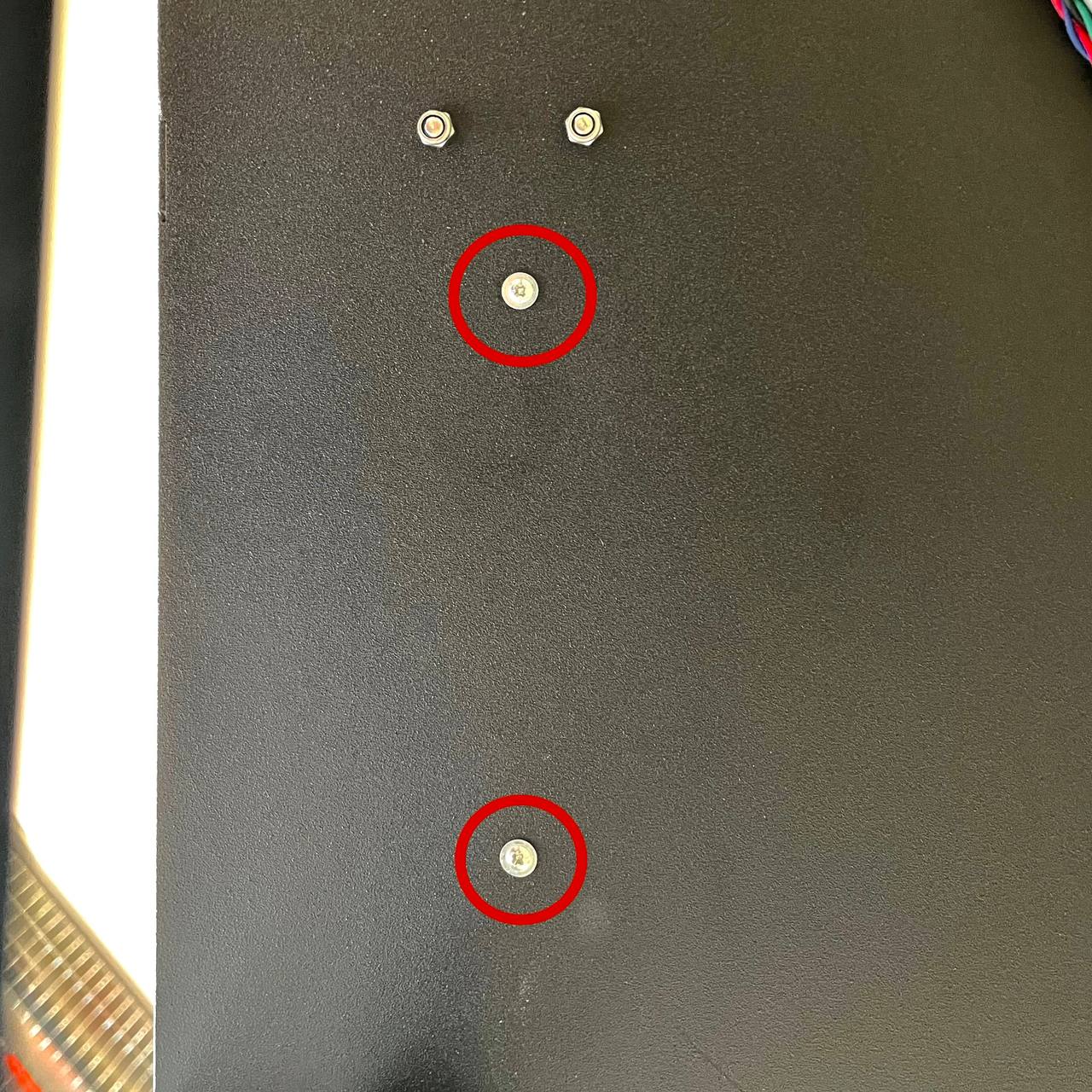
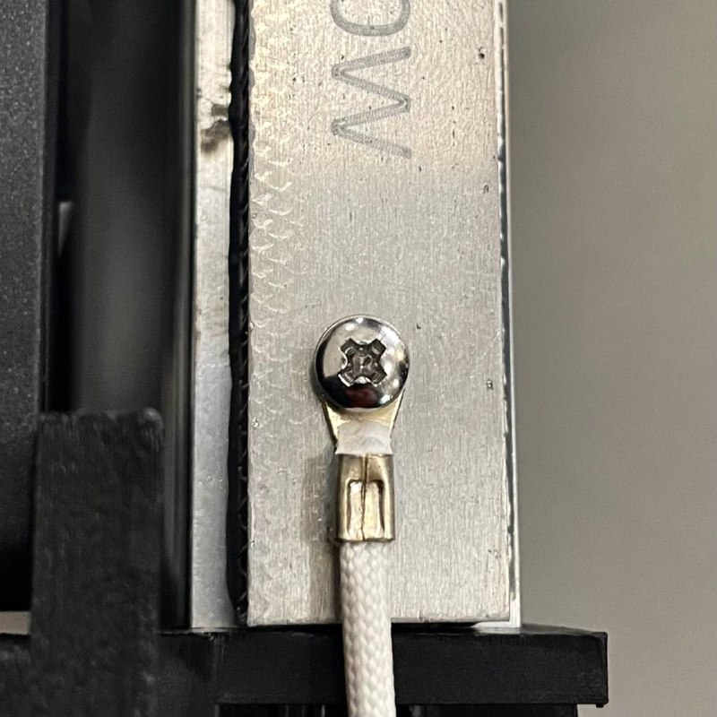
- Unscrew Sensor: Locate the temperature sensor attached to the chamber heater element. Using the PH2 Phillips Screwdriver, unscrew the sensor from its mounting point on the heater block.
Route and Replace the Sensor
- Access Wiring: Open the rear access doors of the printer.
- Cut Zip Ties: Locate the chamber heater sensor cable. Using Wire Cutters, snip the zip ties securing this specific sensor cable. Avoid cutting other wires.
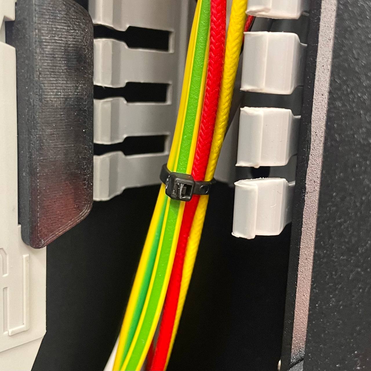
- Disconnect Sensor: Trace the sensor cable to the mainboard. Identify the chamber heater temperature sensor connector (refer to the Wiring Schematic if unsure) and unplug it.
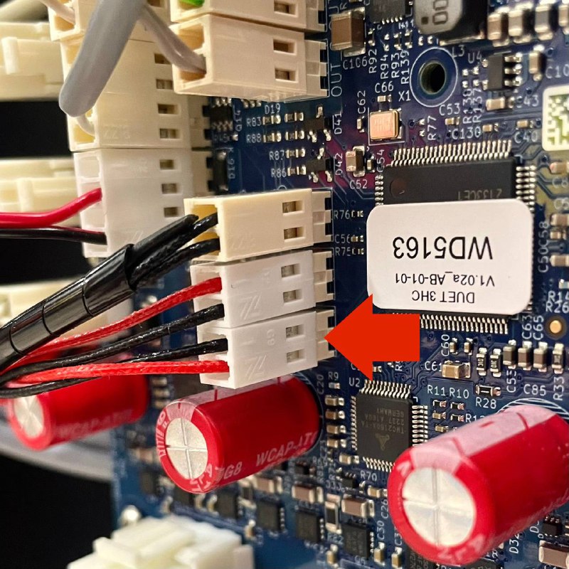
- Attach New Sensor: Cut off the connector from the old sensor, firmly tie the wires to the end of the new sensor (the sensor end), and wrap the connection with tape. The connection must be smooth and strong enough to pull through the cable channels without snagging or separating.
- Pull New Sensor Wire: Gently pull the old sensor wire out, guiding the new sensor wire along the same path through the rear compartment to the chamber heater assembly. Pull slowly; if it snags, check the path.
Avoid excessive force on the new wire
Pulling too hard can damage the new sensor's wiring. If it snags, back off and clear the path rather than forcing it.
- Disconnect Old Sensor: Once routed, remove the tape and separate the old sensor from the new one.
- Connect New Sensor: Plug the new connector into the correct socket on the mainboard.
Reassembly and Testing
- Apply Thermal Paste: Apply a small amount of Thermal Paste to the metal surface of the new sensor.
- Mount Sensor: Screw the new sensor back into its mounting point on the chamber heater element using the PH2 Phillips Screwdriver. Snug, but do not overtighten.
- Secure Heater Assembly: Screw the chamber heater assembly back to the frame using the PH2 Phillips Screwdriver.
- Secure Wiring: Route the new sensor cable neatly in the rear compartment and secure with new Zip Ties.
- Final Checks: Return the printer to its normal position, close the rear access doors, and plug in the power cord.
- Test Sensor: Power on the printer. In the Web Interface, start heating the chamber (for example to
50°C) and confirm the reading rises correctly and stabilizes near the target.
3. Chamber Temperature Sensors
These sensors monitor the ambient air temperature inside the build chamber, separate from the bed and heater element.
Cool the printer and mind the hammer and punch
Power off and unplug the printer and let it cool completely. Use the hammer and punch carefully to avoid damaging the chassis or injuring yourself.
Print the holders first
If possible, print the replacement Sensor Holders beforehand in a high-temperature material (for example Nylon CF or GF).
Remove Old Sensors and Holders
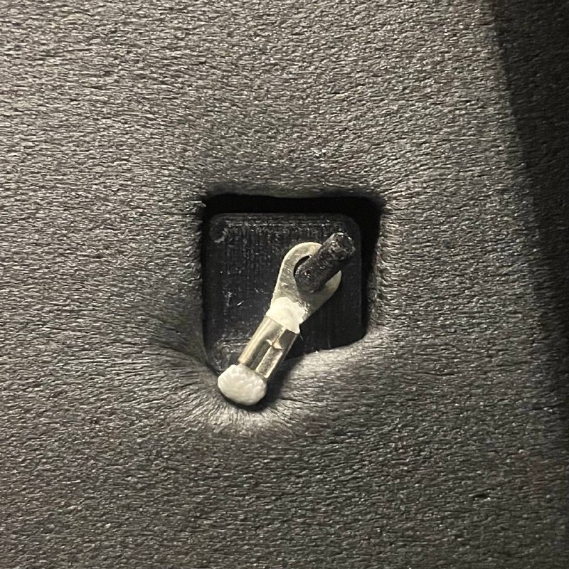
- Release Sensors: Locate the chamber temperature sensors inside the chamber. Unclip or slide the sensor bulb/tip from its printed holder and let it hang freely for now.
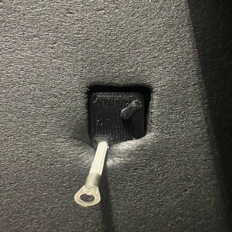
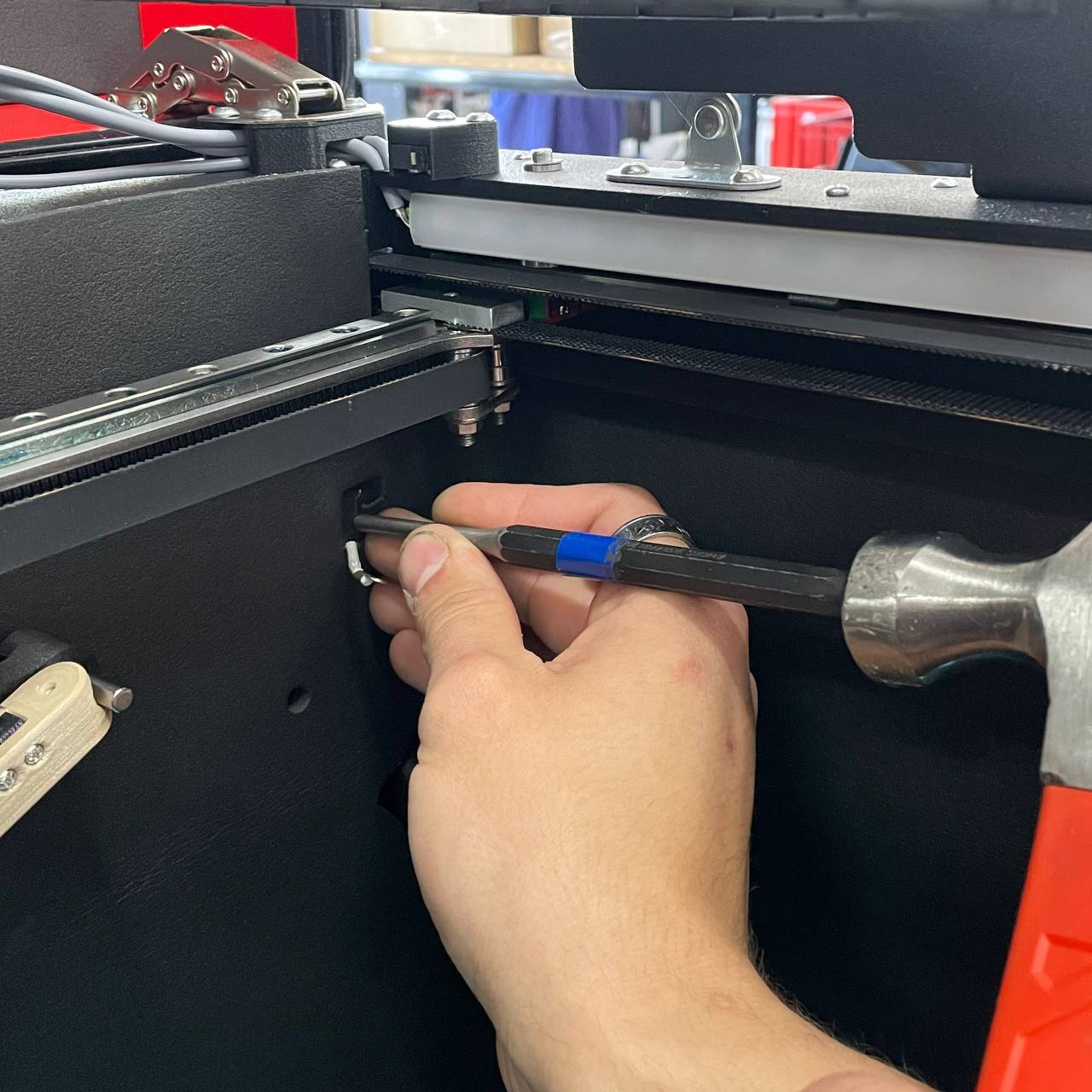
- Remove Holders: Place the Drift Punch Tool against the base of the printed sensor holder where it inserts into the chassis wall. Using the Hammer, give firm, controlled taps to push the holder from the inside of the chamber towards the outside. Remove all holders.
Tap gently to avoid damaging the chamber wall
Tap progressively rather than with heavy blows, and support the area from the other side if you can.
Route and Replace the Sensor
- Access Wiring: Open the rear access doors.
- Cut Zip Ties: Locate the chamber sensor cables. Using Wire Cutters, snip the securing zip ties.
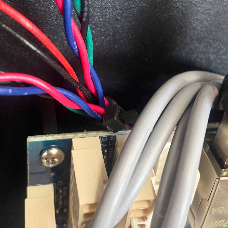
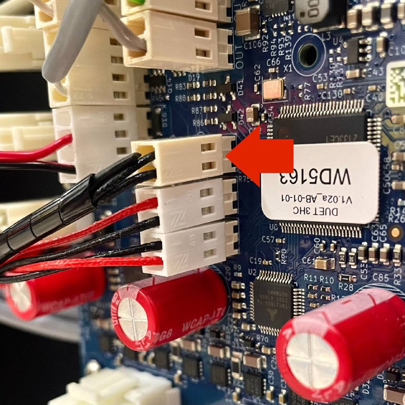
- Disconnect Sensor: Trace the sensor cables to the mainboard. Identify the chamber temperature sensor connector (refer to the Wiring Schematic if unsure) and unplug it.
- Attach New Sensors: Cut off the connectors from the old sensors, firmly tie the wires to the end of the new sensors (the sensor end), and wrap the connection with tape. The connection must be smooth and strong enough to pull through the cable channels without snagging or separating.
- Pull New Sensors Wire: Gently pull the old sensors wire out, guiding the new sensors wire along the same path through the rear compartment to the chamber. Pull slowly; if it snags, check the path.
Avoid excessive force on the new wire
Pulling too hard can damage the new sensor's wiring. If it snags, back off and clear the path rather than forcing it.
- Disconnect Old Sensors: Once routed, remove the tape and separate the old sensors.
- Connect New Sensor: Plug the new connector into the correct socket on the mainboard.
Install New Sensors and Holders
- Prepare Holders: Take the new printed Sensor Holders (or reuse the old ones if undamaged and new ones are unavailable).
- Install Holders:
- Feed the new sensor wire through the hole in the chassis wall from the rear compartment into the build chamber.
- From outside the chamber, align the new printed holder with the hole. Make sure the sensor wire sits in the groove in the holder.
- Using the Hammer and Punch Tool (or hand pressure if possible), gently tap or press the holder firmly into the chassis hole until it is seated securely.
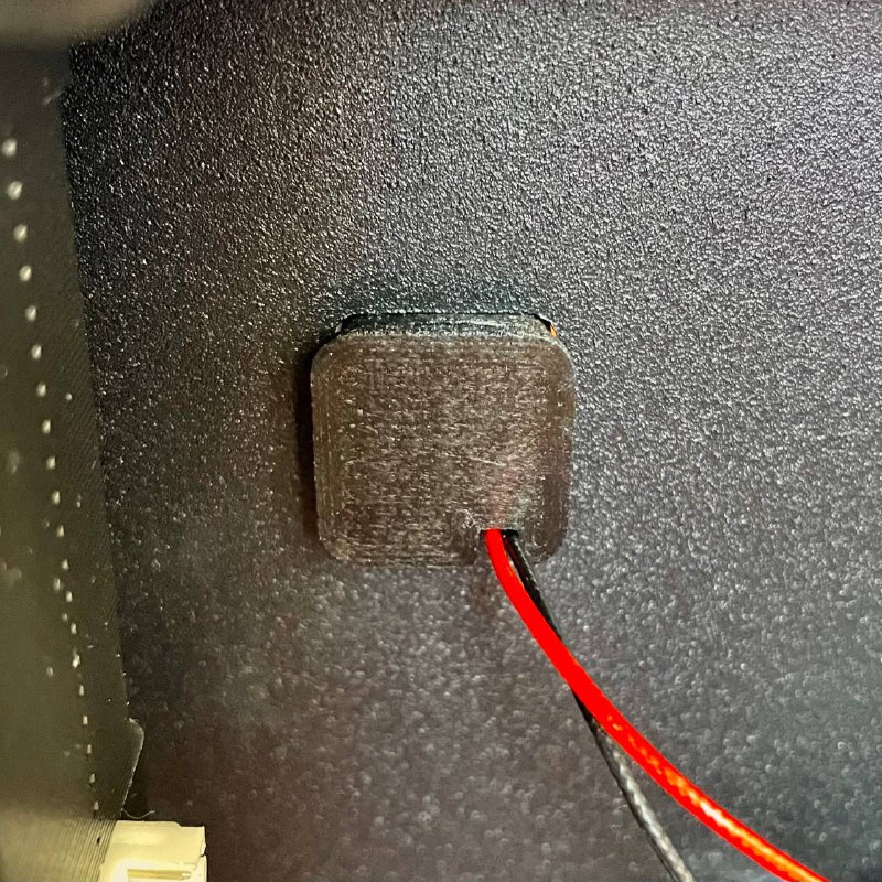
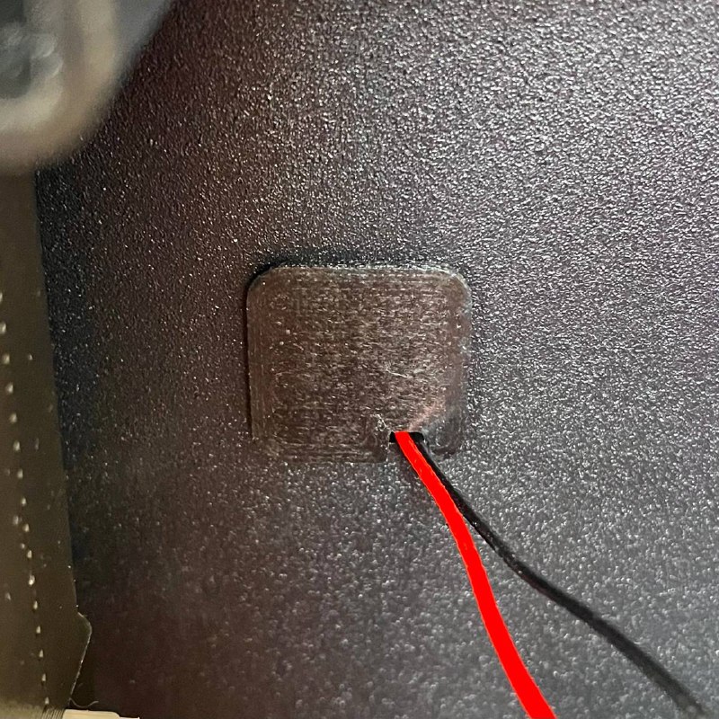
- Mount Sensors: Clip or slide the new sensor tip into place on the newly installed holder. Gently pull any excess wire slack back towards the rear compartment.
Reassembly and Testing
- Secure Wiring: Route the new sensor cables neatly in the rear compartment and secure with new Zip Ties.
- Final Checks: Close the rear access doors and the main printer door, then plug in the power cord.
- Test Sensors: Power on the printer. Check the chamber temperature reading in the Web Interface – it should show a plausible room temperature. Optionally heat the chamber slightly (for example
40°C) and confirm the reading increases.
FAQ
Support
If you could not find an answer here, reach out to our support team.