Maintenance Schedule
Daily, weekly, monthly and yearly service intervals for every part, with expected replacement years and a recommended spare-parts list to keep on the shelf.
Maintenance Schedule outlines inspection, cleaning, and replacement intervals to keep your Vision Miner 22IDEX V4 in optimal condition. Regular maintenance prevents component wear, minimizes downtime, and ensures consistent print quality.
Recommended Spare Parts
Keep these components on hand to minimize downtime during high-temperature printing. This list is based on experience and customer feedback.
Hotend
| Component | Quantity |
|---|---|
| Heat Break | 4 |
| Nozzle | 2 |
| Hot Block | 2 |
| Tool Heater (50W 24V) | 2 |
| PT1000 Thermocouple | 4 |
Fans and Air Filtration
| Component | Quantity |
|---|---|
| HeatSink Cooling Fan 2510 | 4 |
| Part Cooling Blower Fan | 2 |
| Chamber Circulation Fan | 1 |
| HEPA Filter | 1 |
| HEPA Filter Fan Set - Rev 2 | 1 |
Motion System
| Component | Quantity |
|---|---|
| Belt - Full Set | 1 |
| Belt X - Axis | 2 |
| Belt Y - Axis | 2 |
| GT2 Idler Pulley Set | 1 |
Sensors and Wiring
| Component | Quantity |
|---|---|
| Build Plate Thermistor | 1 |
| Chamber Air Temperature Sensor | 1 |
| Z - Probe GND Wires | 1 |
Consumables and Tools
| Component | Quantity |
|---|---|
| Nano Polymer Adhesive | 2 |
| Grease | 1 |
| Boron Nitride Paste | 1 |
| Purge Bucket Nozzle Brush Set | 1 |
| Nozzle Cleaning Needle Set | 1 |
Daily Maintenance
| Component | Inspect/Test | Clean | Adjust | Replace if needed |
|---|---|---|---|---|
| Build Plate | ✓ |
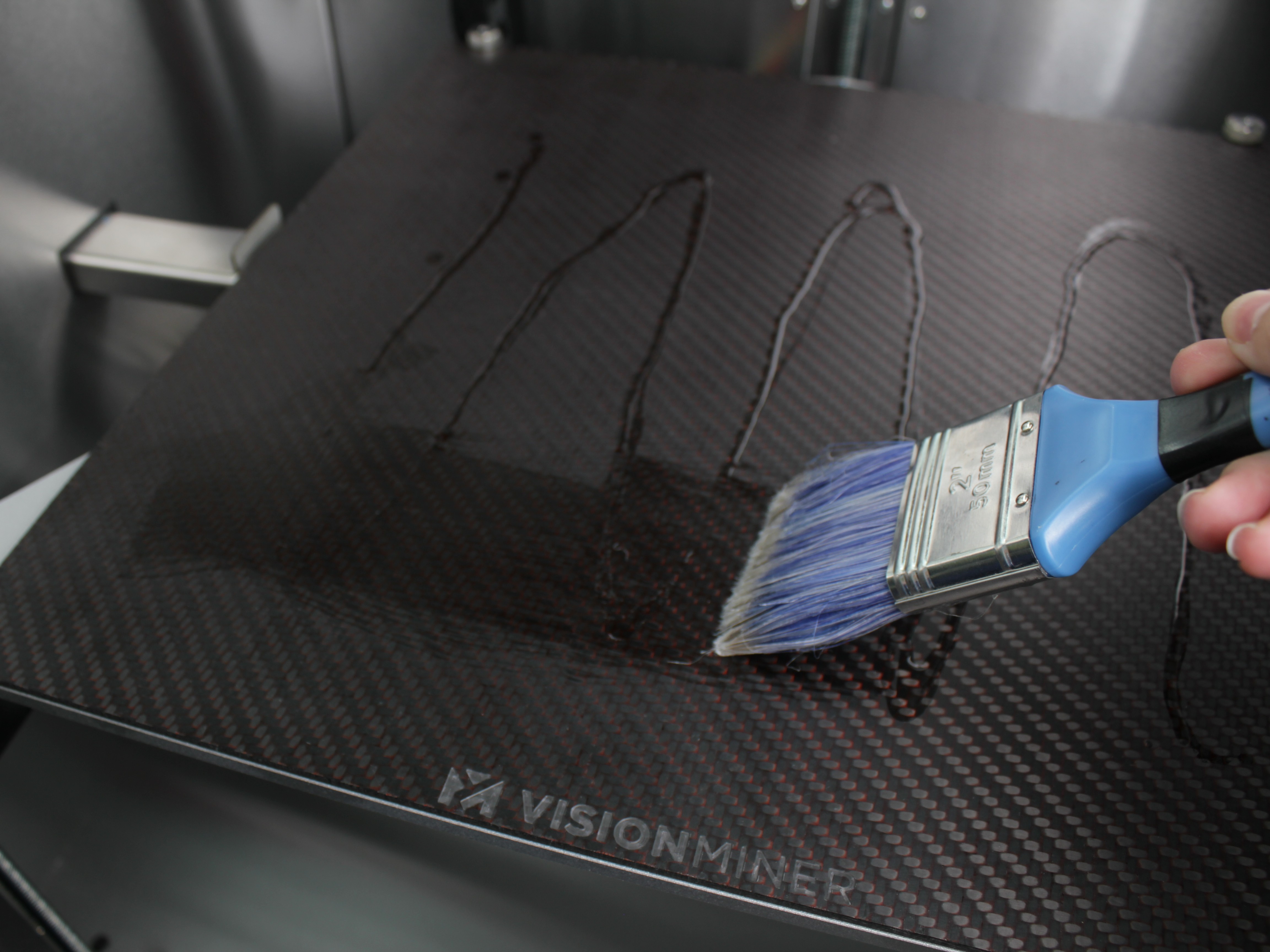
- Build Plate - Clean with isopropyl alcohol after each print to remove residue. Apply a full coat of Nano Polymer Adhesive after cleaning depending on condition.
Weekly Maintenance
| Component | Inspect/Test | Clean | Adjust | Replace if needed |
|---|---|---|---|---|
| Purge Bins | ✓ | |||
| Z-Axis Lead Screws | ✓ | |||
| Chamber | ✓ |
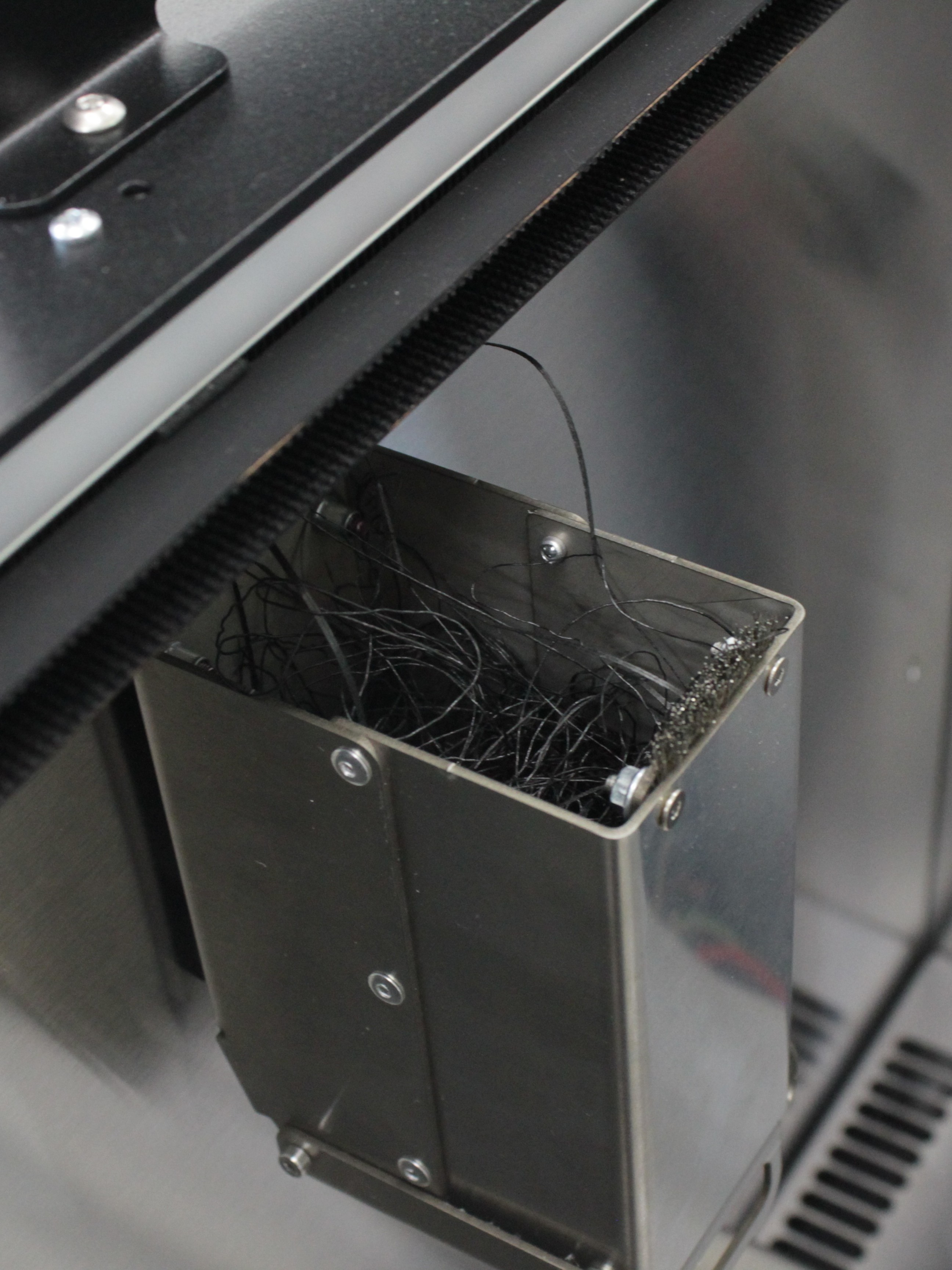
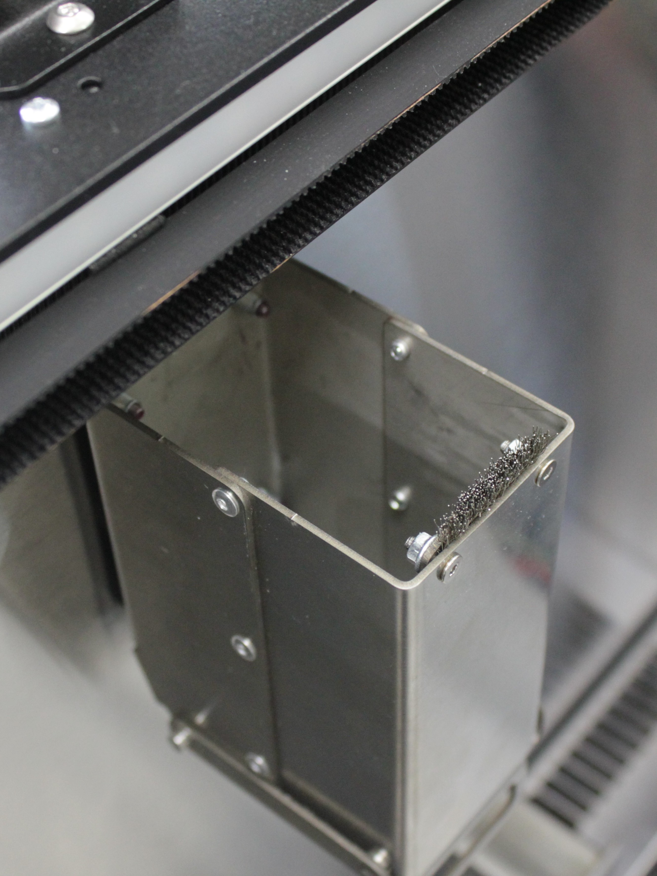
- Purge Bins - Empty bins with tweezers, removing all accumulated filament. Ensure nozzle brushes have no filament residue.
- Z-Axis Lead Screws - Clean lead screws with a paper towel. Remove old lubricant.
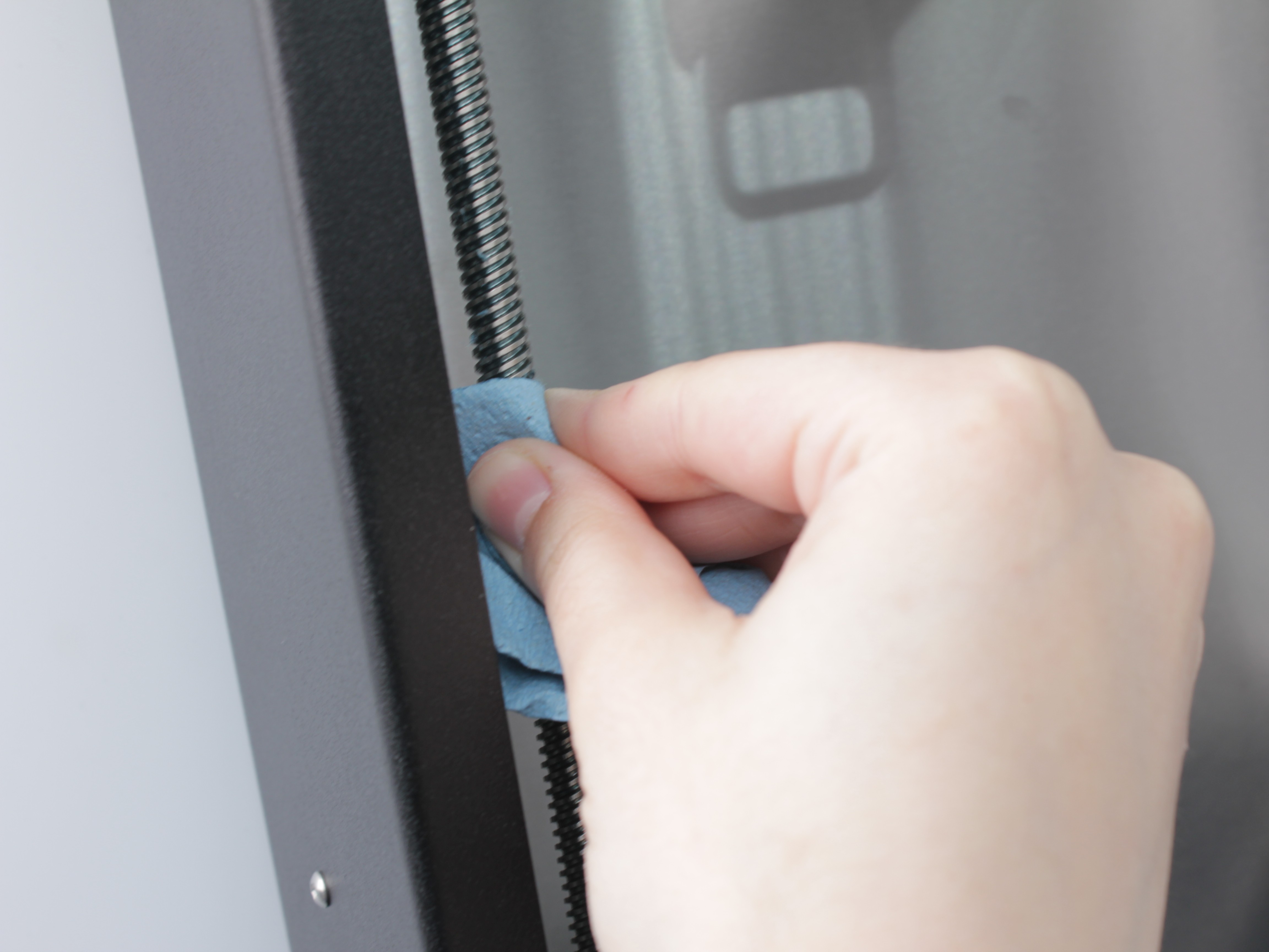
Apply new lubricant evenly.
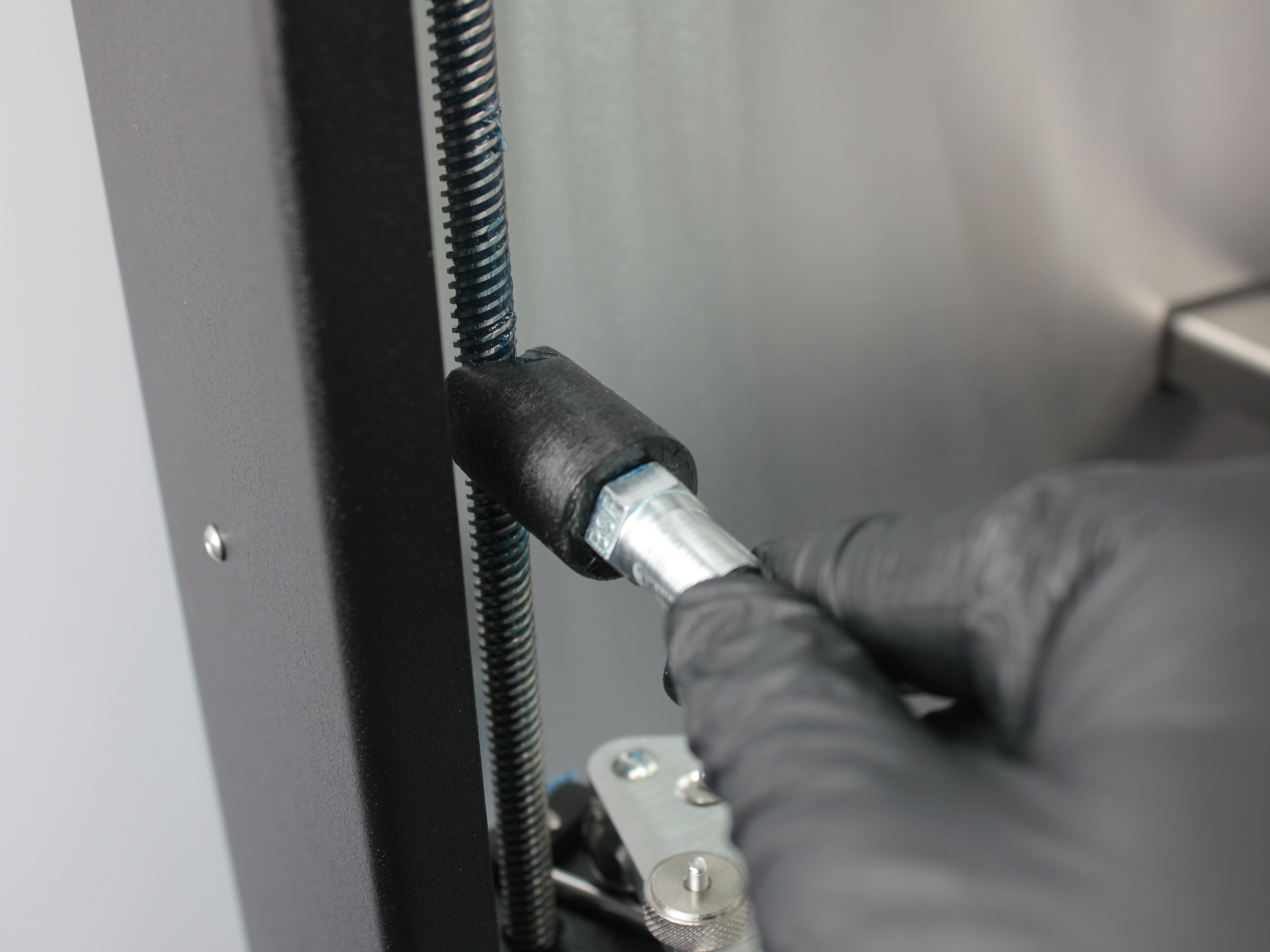
Verify lubricant is evenly distributed across all threads.
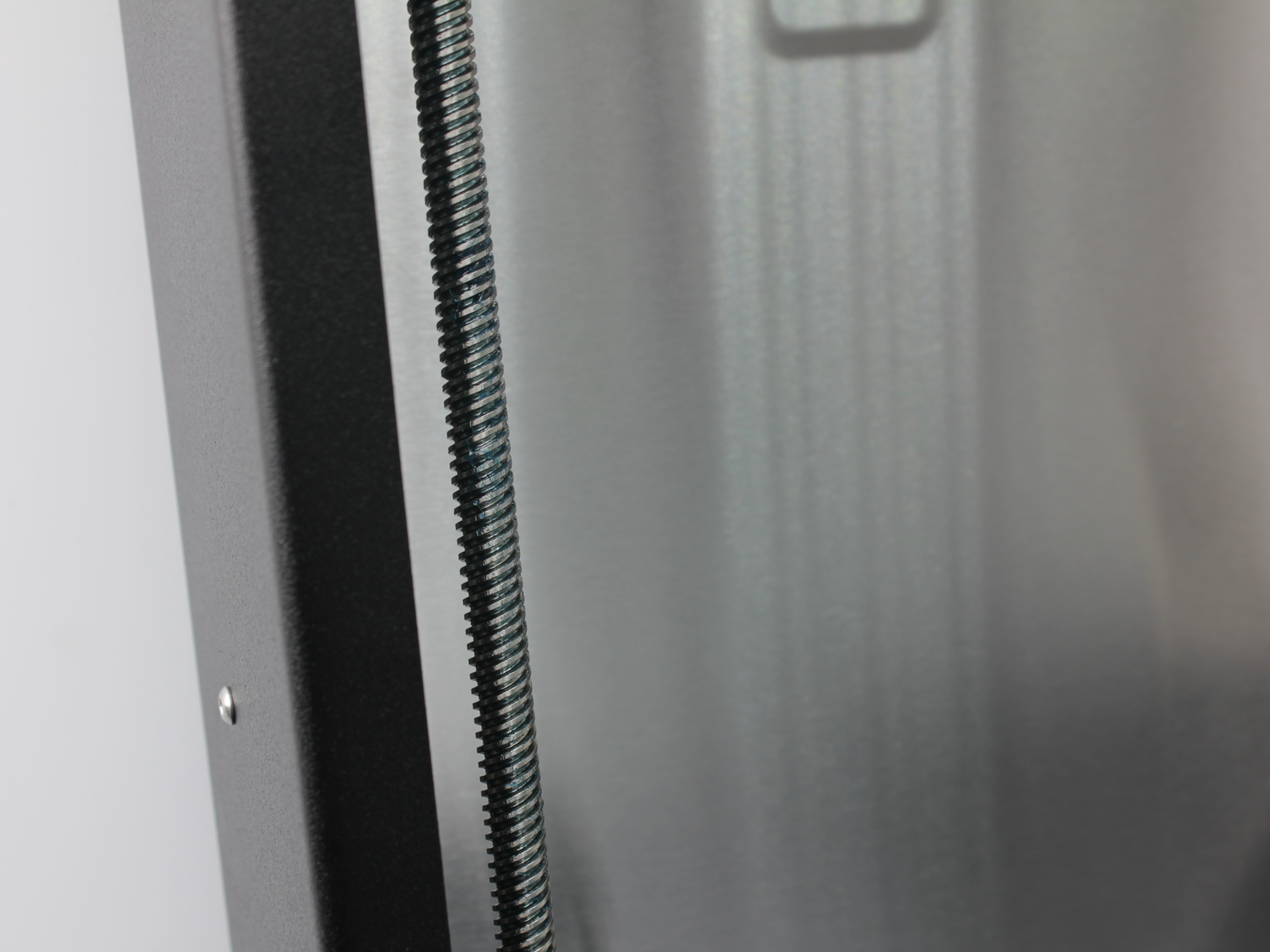
For detailed lubrication procedures and troubleshooting, see the Lubrication Guide.
- Chamber - Use a vacuum cleaner or compressed air to remove dust and filament particles.
High-volume printing
If you print frequently or with materials that generate significant debris, perform chamber cleaning more often (every 2-3 days).
Monthly Maintenance
| Component | Inspect/Test | Clean | Adjust | Replace if needed | Expected replacement |
|---|---|---|---|---|---|
| Extruders | ✓ | ✓ | ✓ | ||
| Belt Tension | ✓ | ✓ | |||
| Hotend Temperature Sensors | ✓ | ✓ | 1st Year | ||
| Hotend Heaters | ✓ | ✓ | 2nd Year | ||
| Radiator Cooling Fans | ✓ | 1st Year | |||
| Hot End Ground Wires | ✓ | ||||
| Z-Probe Wiring | ✓ | ||||
| XY Linear Rails | ✓ | ✓ | |||
| Z-Axis Lead Screws | ✓ | ✓ | ✓ | ||
| General Printer Cleaning | ✓ |
- Extruders - Disassemble and clean extruder drive gears.
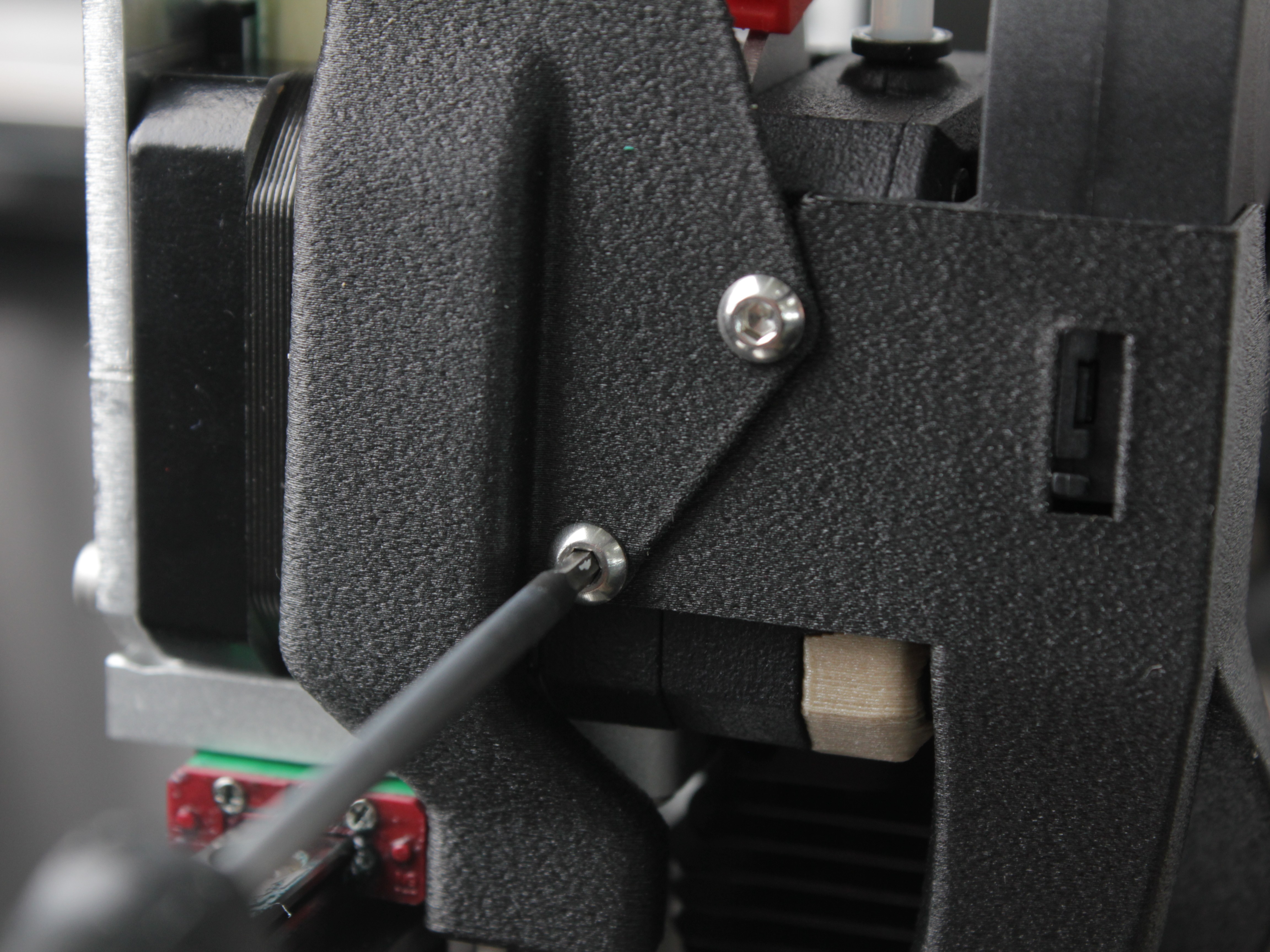
Step 1: Remove 2 screws securing fan shroud and cable protection cover.
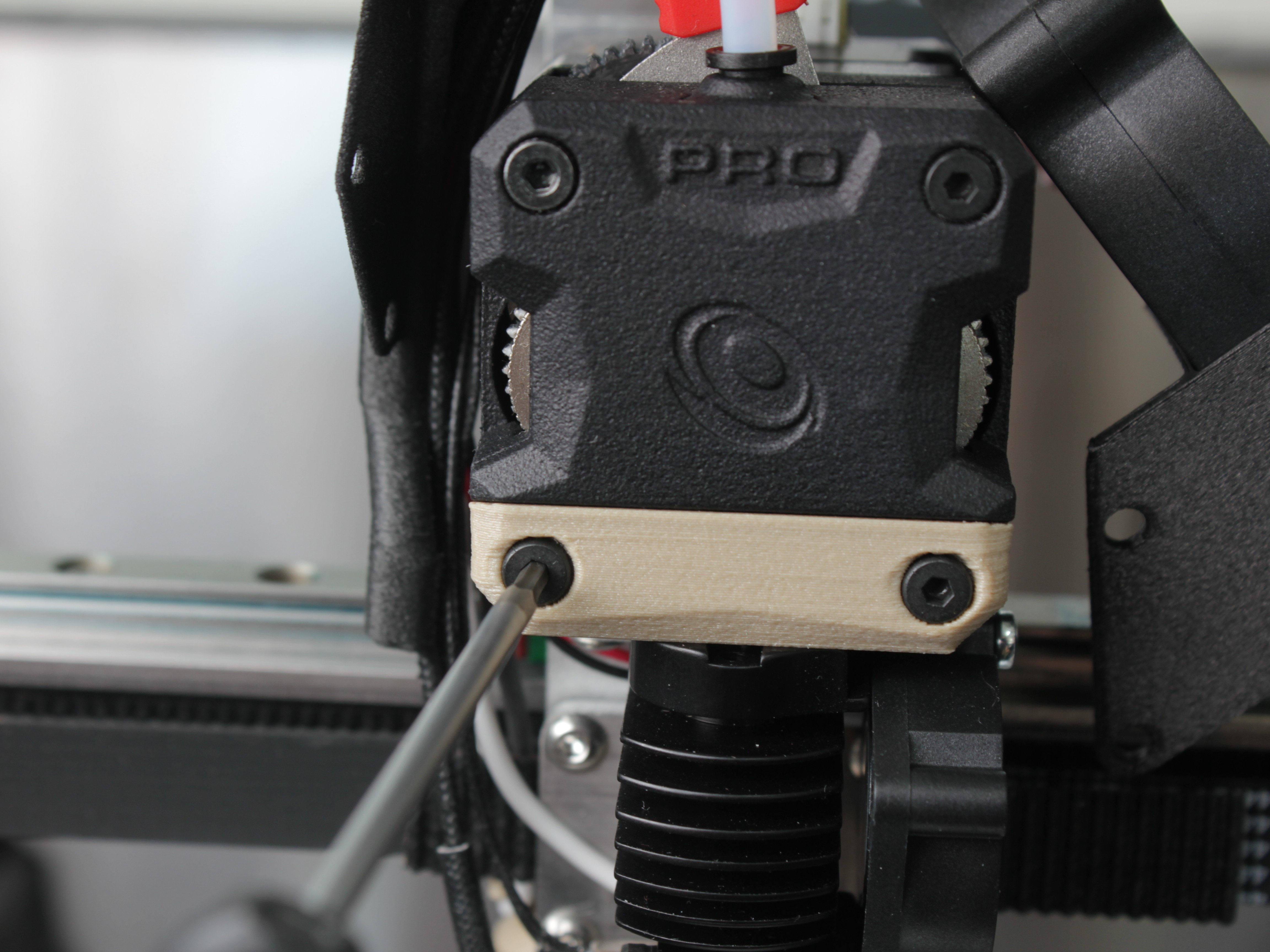
Step 2: Remove 4 screws on the front panel of the extruder.
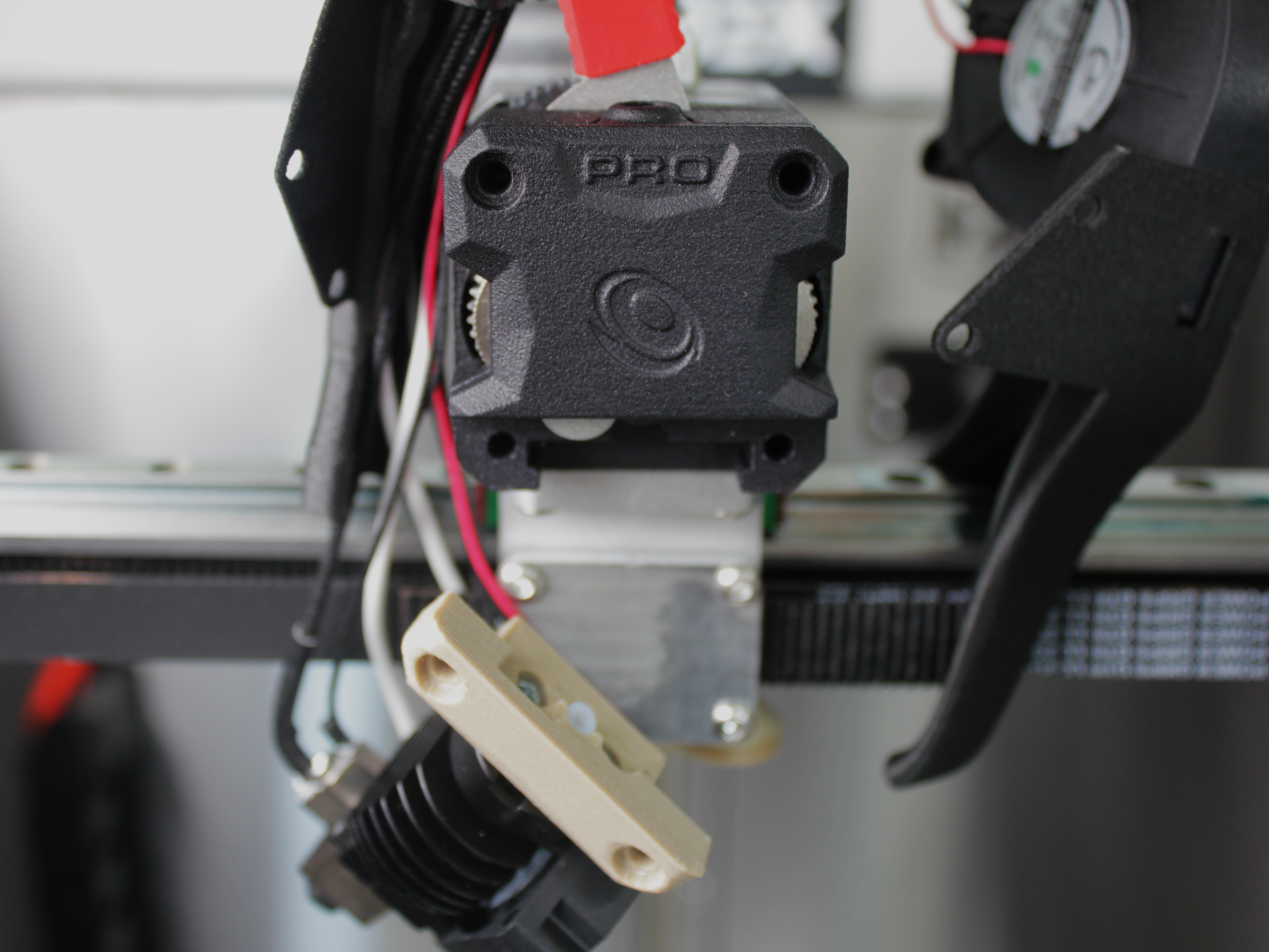
Step 3: Remove the radiator adapter bracket (printed part holding the hotend radiator).
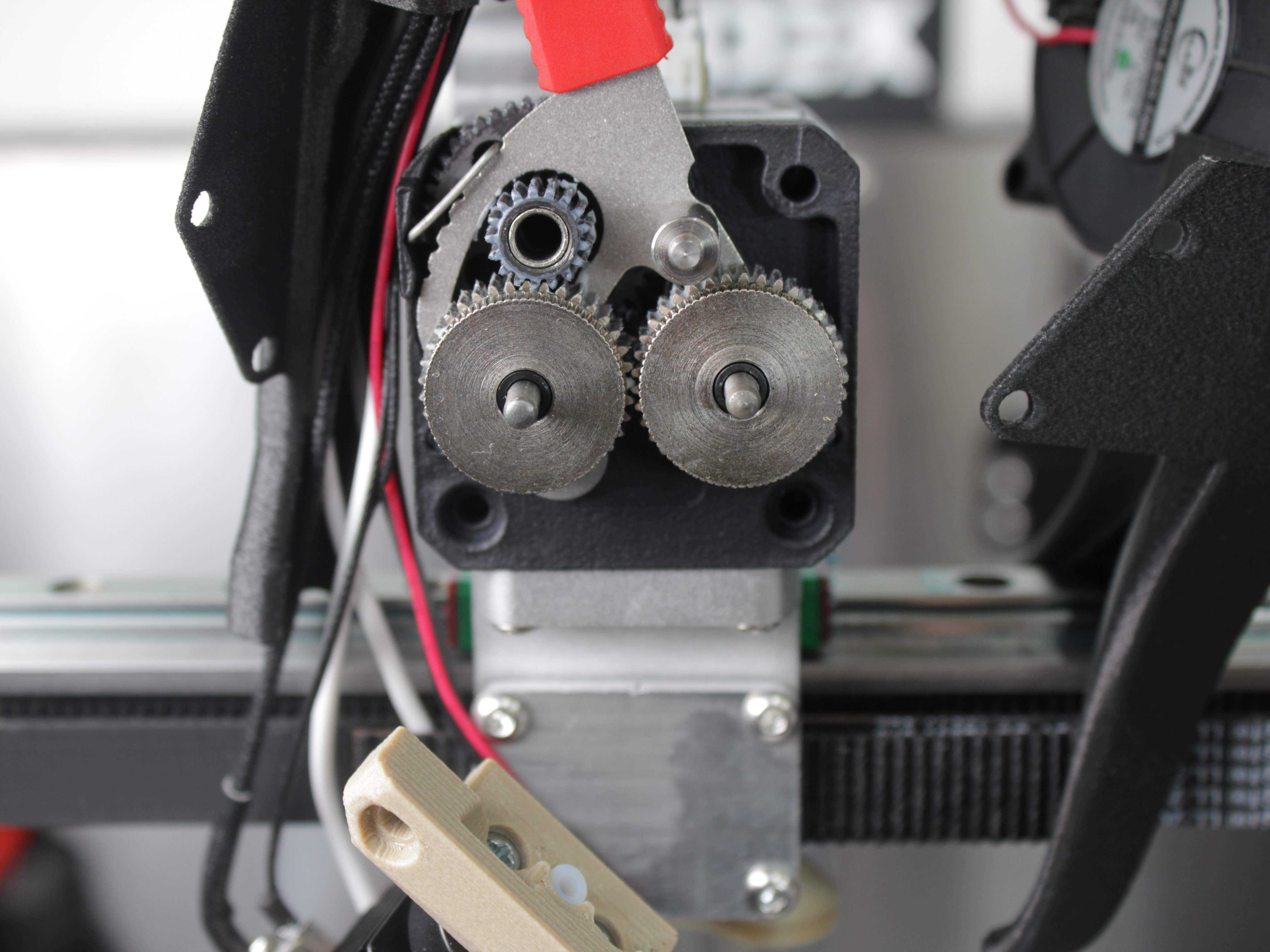
Step 4: Remove the front extruder panel to expose drive gears for cleaning and lubrication. Reassemble in reverse order.
For additional information on extruder disassembly, see the Extruder Replacement Guide.
- Belt Tension - Check and Adjust Tension, All 4 Belts
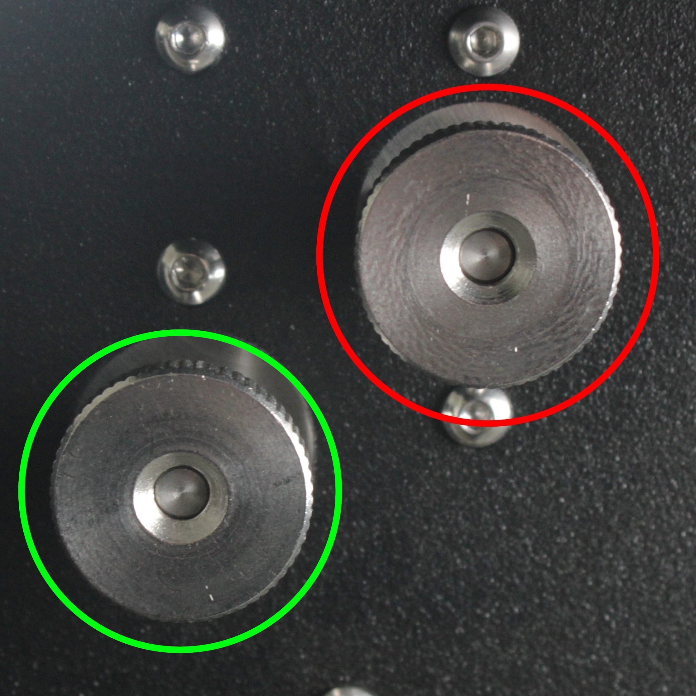
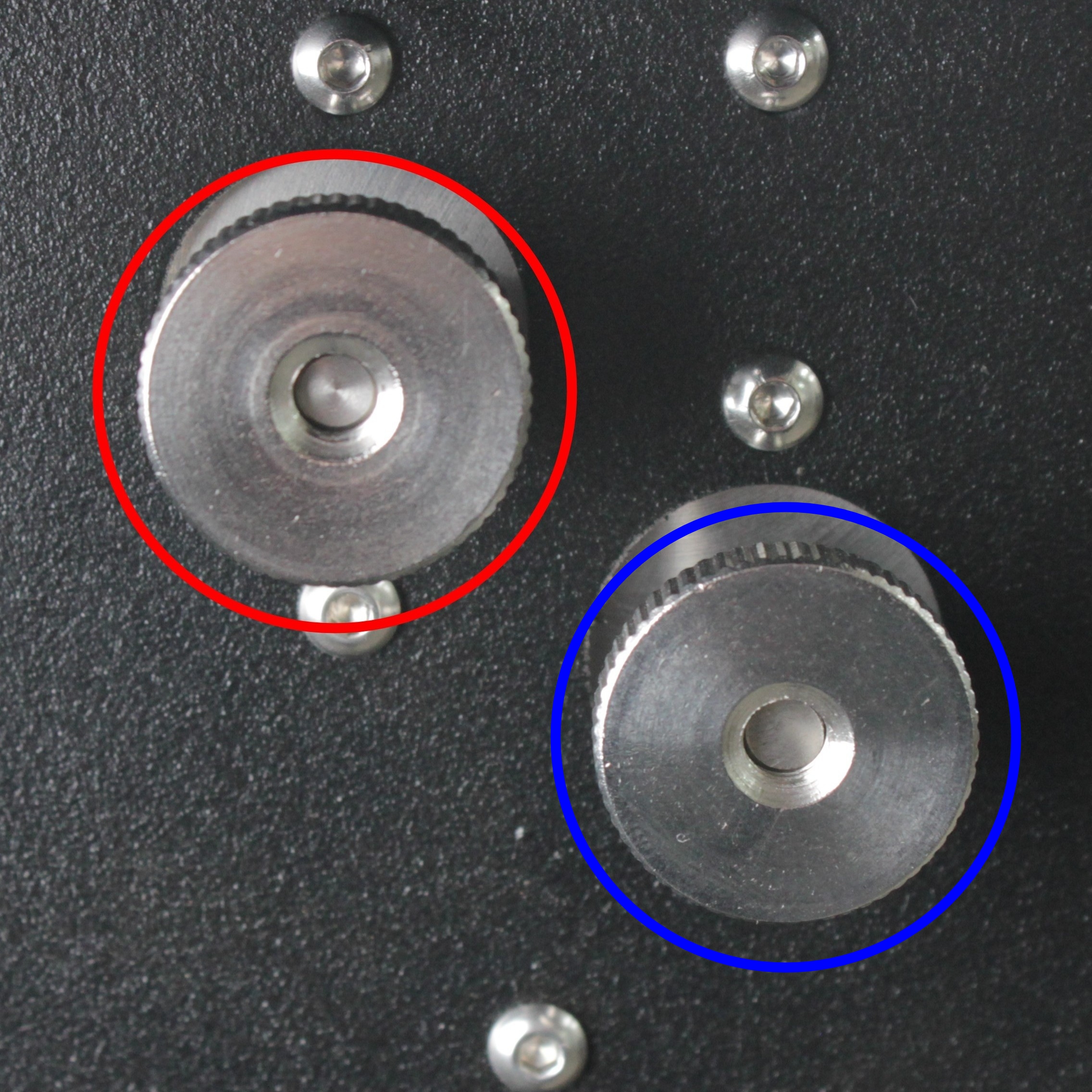
Color markings on the photos above:
| Circle Color | Belt Tensioner |
|---|---|
| 🔴 Red | Y-axis belt tensioners |
| 🟢 Green | Tool 0 (X-axis) belt tensioner |
| 🔵 Blue | Tool 1 (U-axis) belt tensioner |
Verify tensioners and idlers rotate smoothly without binding. See Belt Tension Guide for detailed instructions.
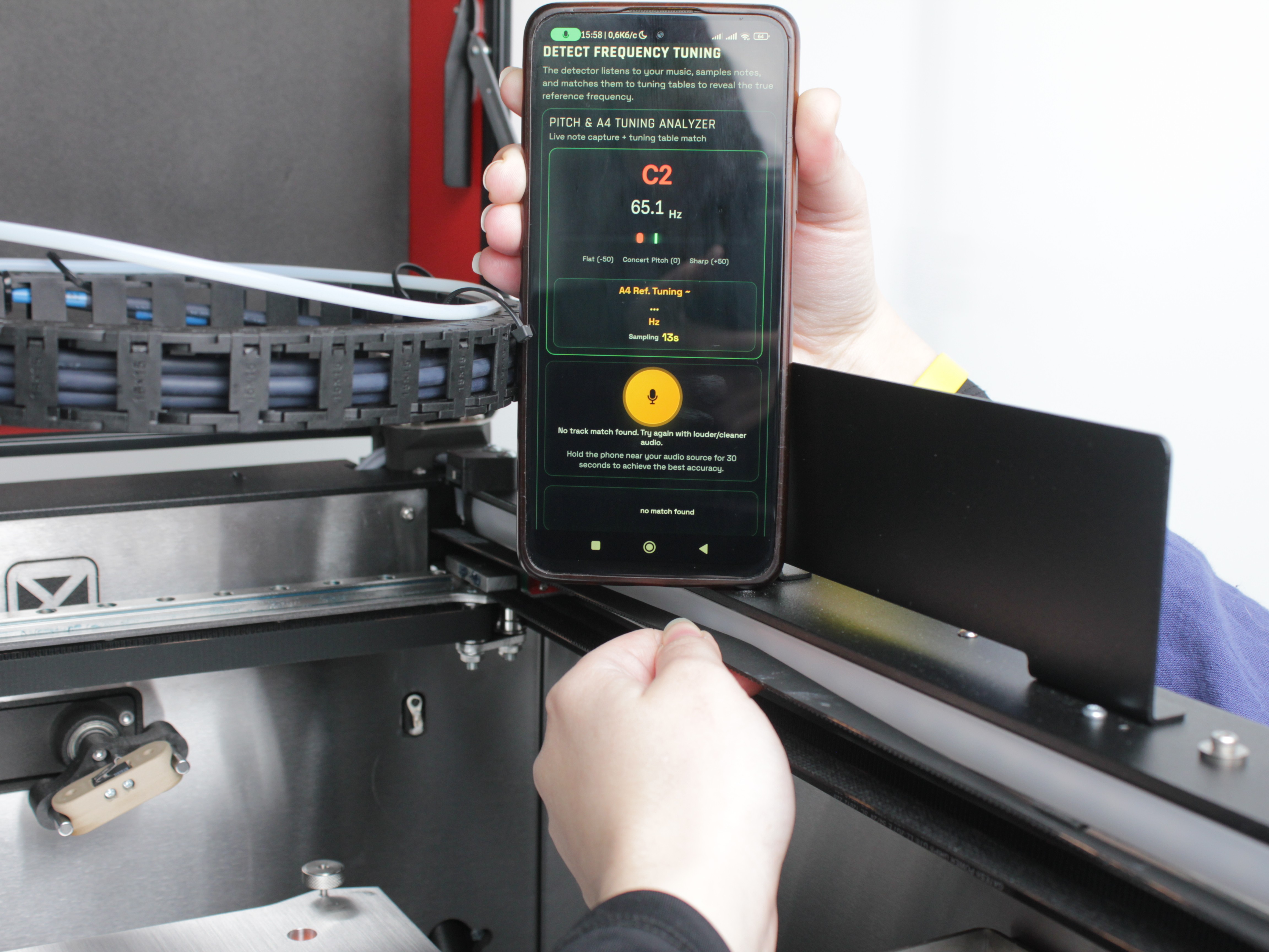
- Hotend Temperature Sensors - Inspect wiring for damage or wear. Monitor temperature readings in the Web Interface for unusual spikes or fluctuations. Replace the sensor if readings are unstable.
- Hotend Heaters - Inspect wire insulation for cracks or heat damage. Replace the heater if wiring is compromised.
- Radiator Cooling Fans - Verify the fans spin smoothly and quietly. Test by preheating the tool and lightly touching the fan blade to check motor torque. Clean the dust from the fan blades if needed.
- Hot End Ground Wires - Verify ground wires are intact with good insulation. Check secure connection to hotend.
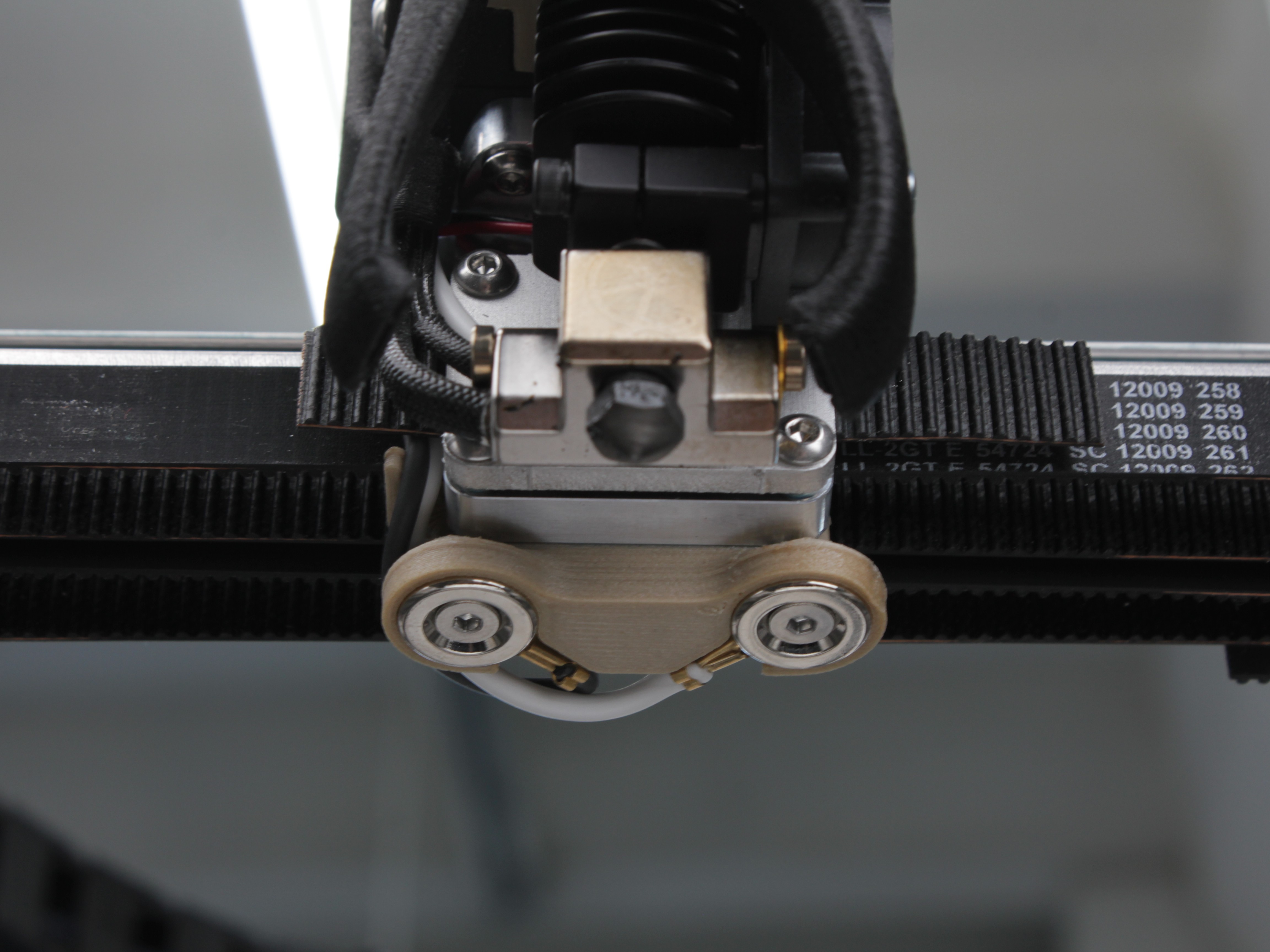
Check Z-probe wiring for damage or wear. Ensure connections are secure.
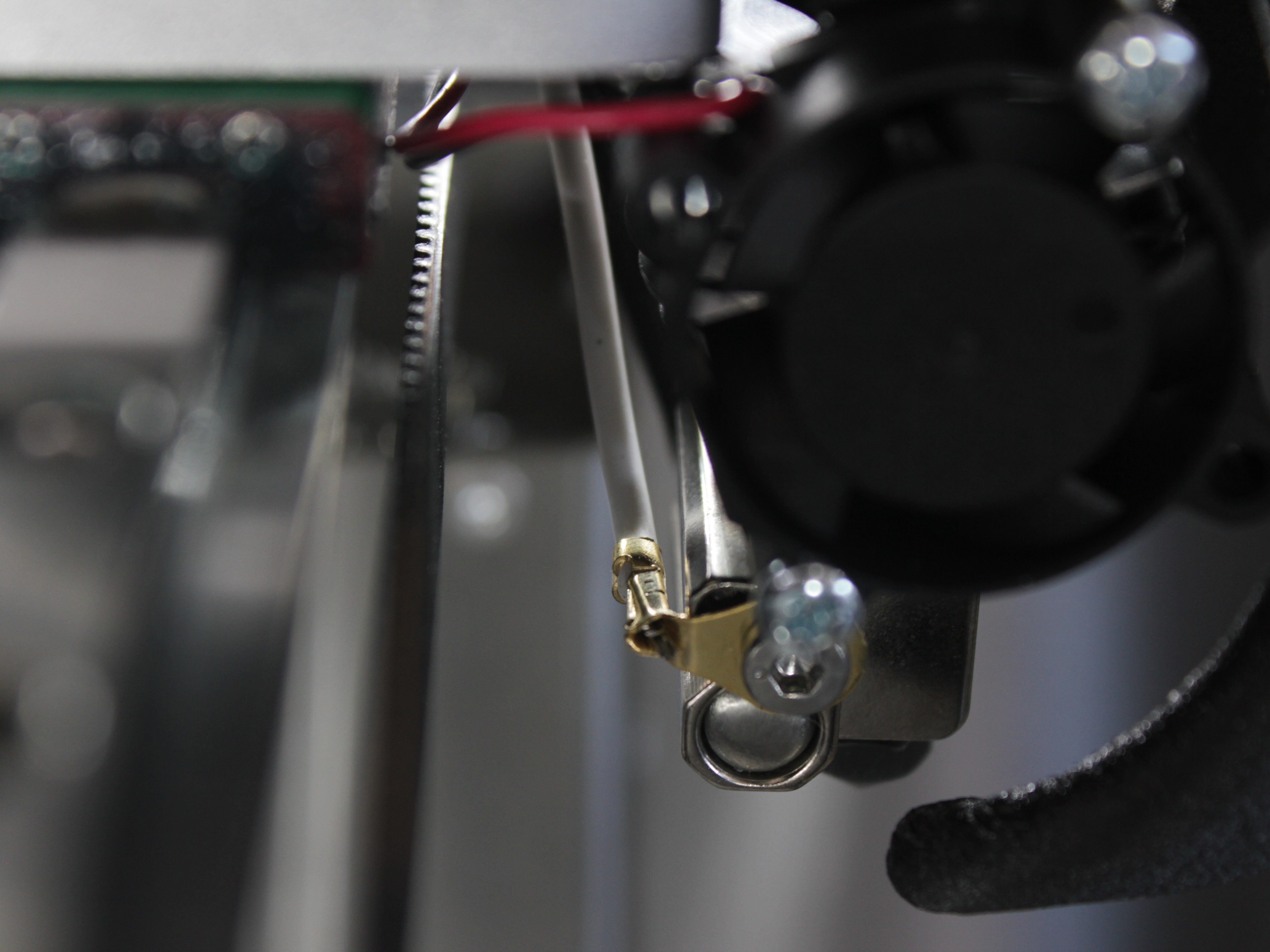
Verify hotend ground wire is intact with good insulation and secure connection.
- XY Linear Rails - Inspect the rails for dirt or debris. Wipe them clean with a lint-free cloth if contamination is present. Apply fresh lubricant if the rails appear dry.
- Z-Axis Lead Screws - Wipe off old lubricant from the lead screws using a paper towel. Apply fresh lubricant evenly along the screws.
- General Printer Cleaning - Power off the printer completely. Use a soft brush and a vacuum to remove dust and debris from the entire printer:
- Clean all exterior panels and doors
- Vacuum the build chamber thoroughly
- Remove filament debris from all areas
- Electronics bay: Use an anti-static brush carefully. Vacuum dust gently to help prevent electrical shorts
- Inspect all cable routing and secure any loose wiring
Electronics cleaning precautions
When cleaning the electronics bay, use an anti-static brush only. Work carefully to avoid damaging components or dislodging connections. Ensure the printer is completely powered off.
Yearly Maintenance
| Component | Inspect/Test | Clean | Adjust | Replace if needed | Expected replacement |
|---|---|---|---|---|---|
| XYU Belt Idlers | ✓ | ✓ | ✓ | 2nd Year | |
| Filament Sensors | ✓ | ✓ | 3rd Year | ||
| Part Cooling Fan | ✓ | ✓ | ✓ | 2nd Year | |
| Chamber Heater Fan | ✓ | ✓ | 2nd Year | ||
| Chamber Circulation Fan | ✓ | ✓ | 2nd Year | ||
| HEPA Filter | ✓ | ✓ | 1st Year | ||
| Z-Motor Lead Screw | ✓ | ✓ (motor) | Varies | ||
| Z-Motor Nut | ✓ | ✓ | 2nd Year | ||
| Bed Thermistor | ✓ | ✓ | 2nd Year | ||
| Heat Breaks | ✓ | ✓ | 2nd Year | ||
| Nozzles | ✓ | ✓ | ✓ | 1st Year | |
| Wiper Brushes | ✓ | ✓ | ✓ | ✓ | 2nd Year |
| Microswitches XYUZ | ✓ | ||||
| XYU Belts | ✓ | ✓ | 5th Year | ||
| Ground Wires | ✓ | ||||
| Electronics Terminal Blocks | ✓ | ✓ | |||
| Z-Probe & Servo Screws | ✓ | ✓ | |||
| Linear Rail Screws | ✓ | ✓ |
- XYU Belt Idlers - Inspect all 8 idlers (4 per side). There are two types:
- Idlers with bearings (Y-axis tensioner and tool tensioners): Check for bearing wear - listen for unusual noise during rotation.
- Idlers on motors: Check for tooth wear - inspect teeth condition visually.
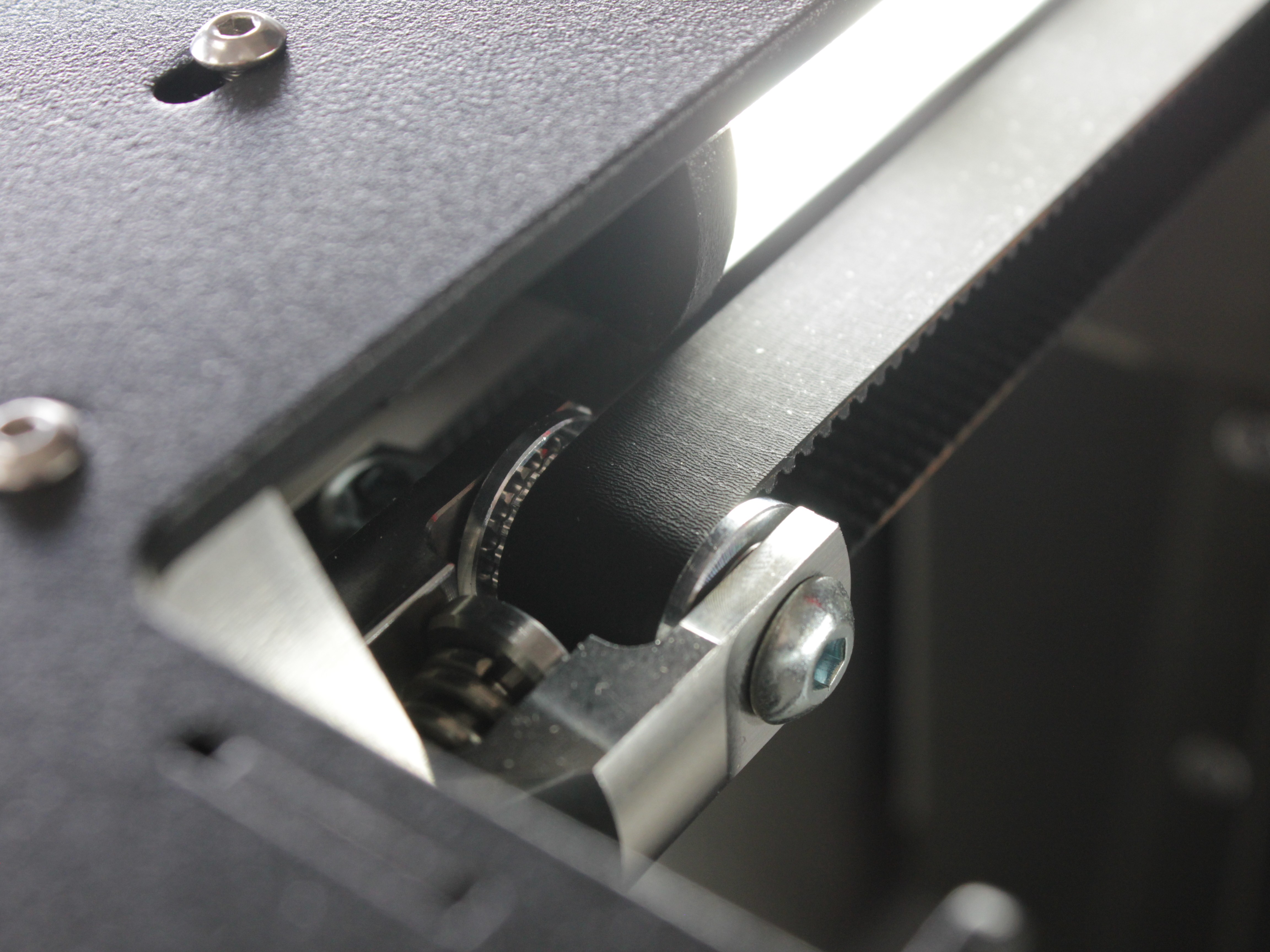
Y-axis tensioner idler - verify smooth rotation without binding. Listen for unusual noise indicating bearing wear.
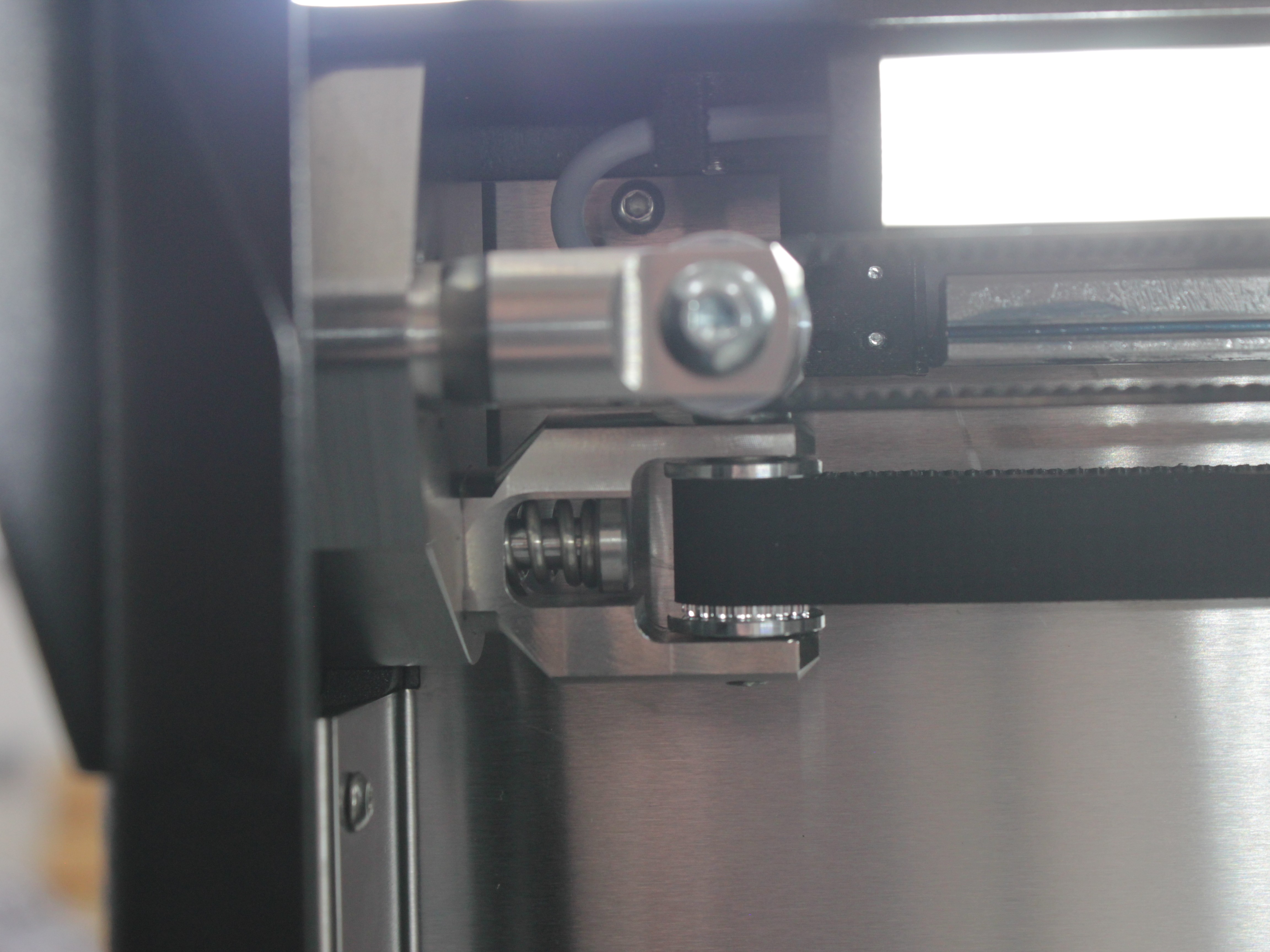
Tool tensioner idler - check bearing condition. Replace if rotation is not smooth or if noise is present.
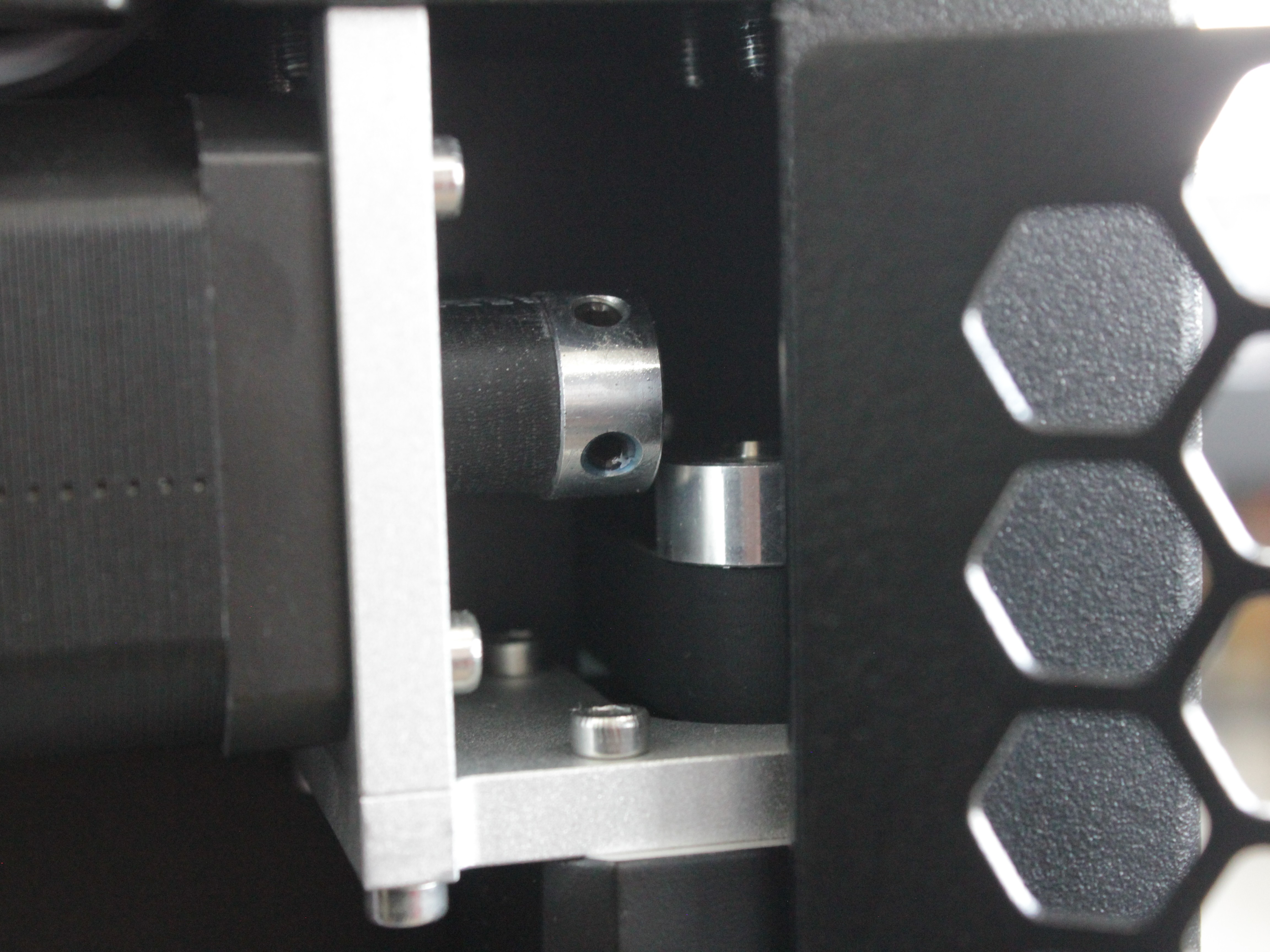
Motor idlers - inspect teeth for wear or damage. Replace if teeth are worn or damaged.
Identical configuration on the opposite side of the machine. For replacement instructions, see the Front Idler Replacement Guide.
- Filament Sensors - Test sensor functionality. Inspect wiring for wear or damage.
- Part Cooling Fan - Activate manually and check for noise and torque. Inspect wiring for wear. Replace if noisy, weak, or wiring is damaged.
- Chamber Heater Fan - Verify airflow and heating efficiency. Check wiring for damage. Replace if airflow is weak, heating takes too long, or fan makes unusual noise.
- Chamber Circulation Fan - Check for noise and torque. Inspect wiring condition. Replace if noisy, weak, or wiring is compromised.
- HEPA Filter - Inspect the filter media. Replace the filter once a year, or every 6 months under heavy use or frequent high-temperature printing. Replace sooner if airflow drops noticeably or the white filter media looks clogged or discolored. The filter cannot be cleaned and reused. See the HEPA Filter Replacement Guide for instructions. Printers with serial number 295 or lower use a Rev 1 filter - contact our support team for a replacement.
- Z-Motor Lead Screw - Check lead screw play by moving it up and down manually. If excessive play or wobble is detected, replace the Z-motor.
- Z-Motor Nut - Hold the lead screw stationary with one hand. Grasp the bed carriage bracket with the other hand and move up/down. If play is detected, replace the Z-motor nut.
- Bed Thermistor - Preheat the build plate and verify temperature stability. Replace if temperature spikes occur.
- Heat Breaks - Inspect for clogs or damage. Replace if clogged or broken.
- Nozzles - Replace based on material type and operating hours.
- Wiper Brushes - Inspect bristles. Replace if damaged.
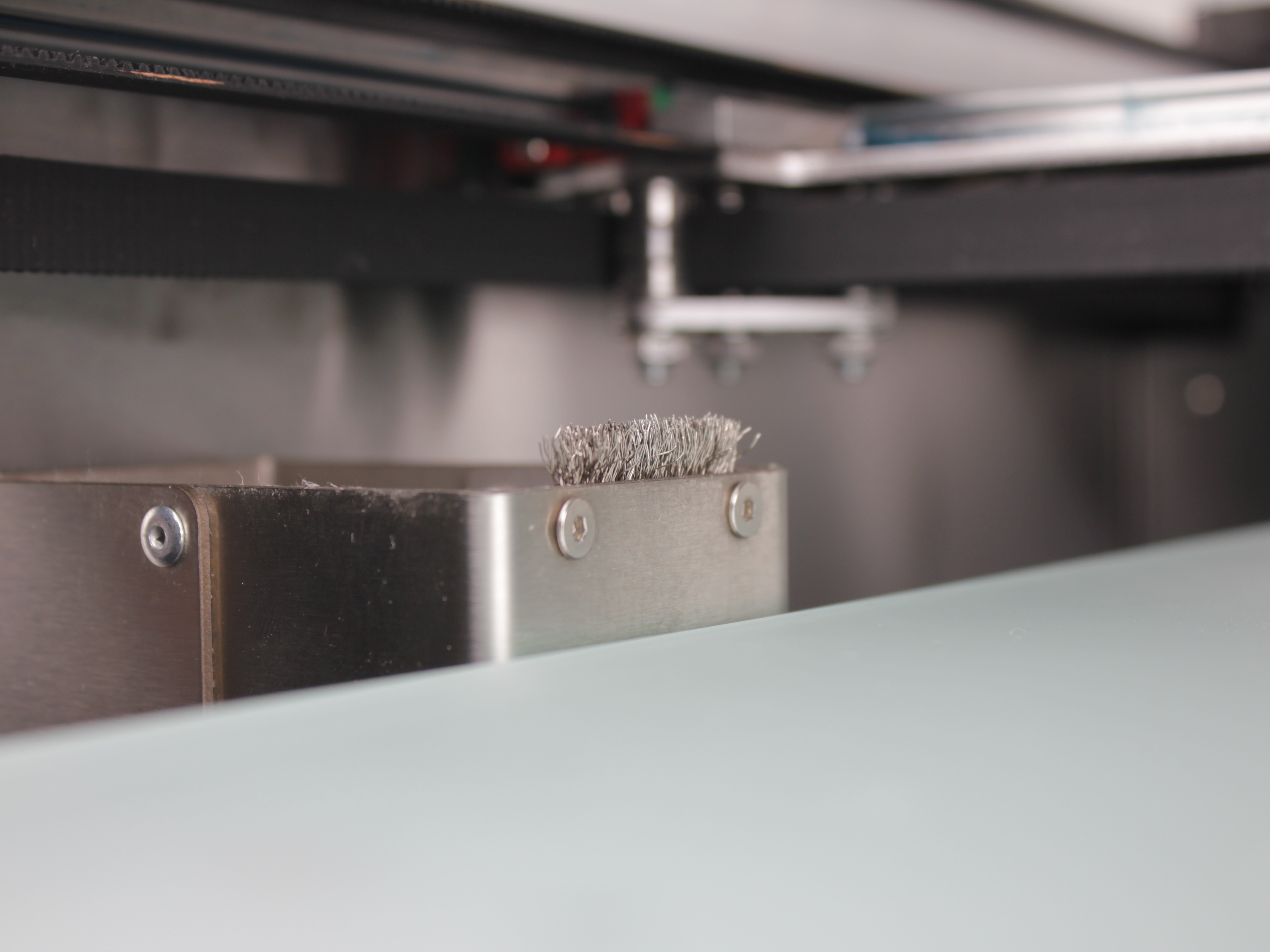
Good wiper brush - bristles are intact and evenly distributed.
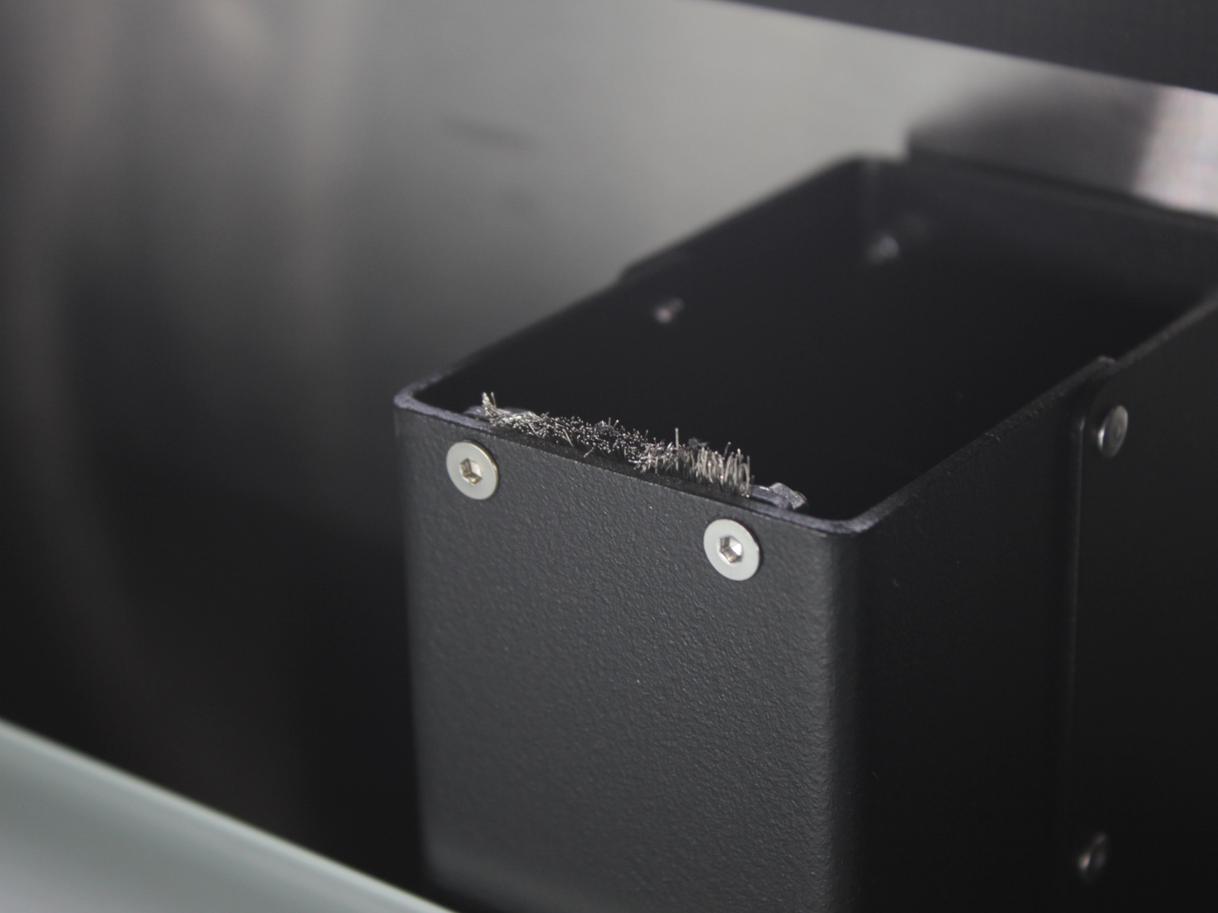
Worn wiper brush - bristles are damaged or missing. Replace immediately. For brush height adjustment instructions, see the Purge Bucket Brush Calibration Guide.
- Microswitches XYUZ - Verify crisp click action and intact levers.
- XYU Belts - Check for wear. Replace if damaged.
- Ground Wires - Verify all grounding wires are intact and connections are tight.
- Electronics Terminal Blocks - Tighten all screws in electronics bay.
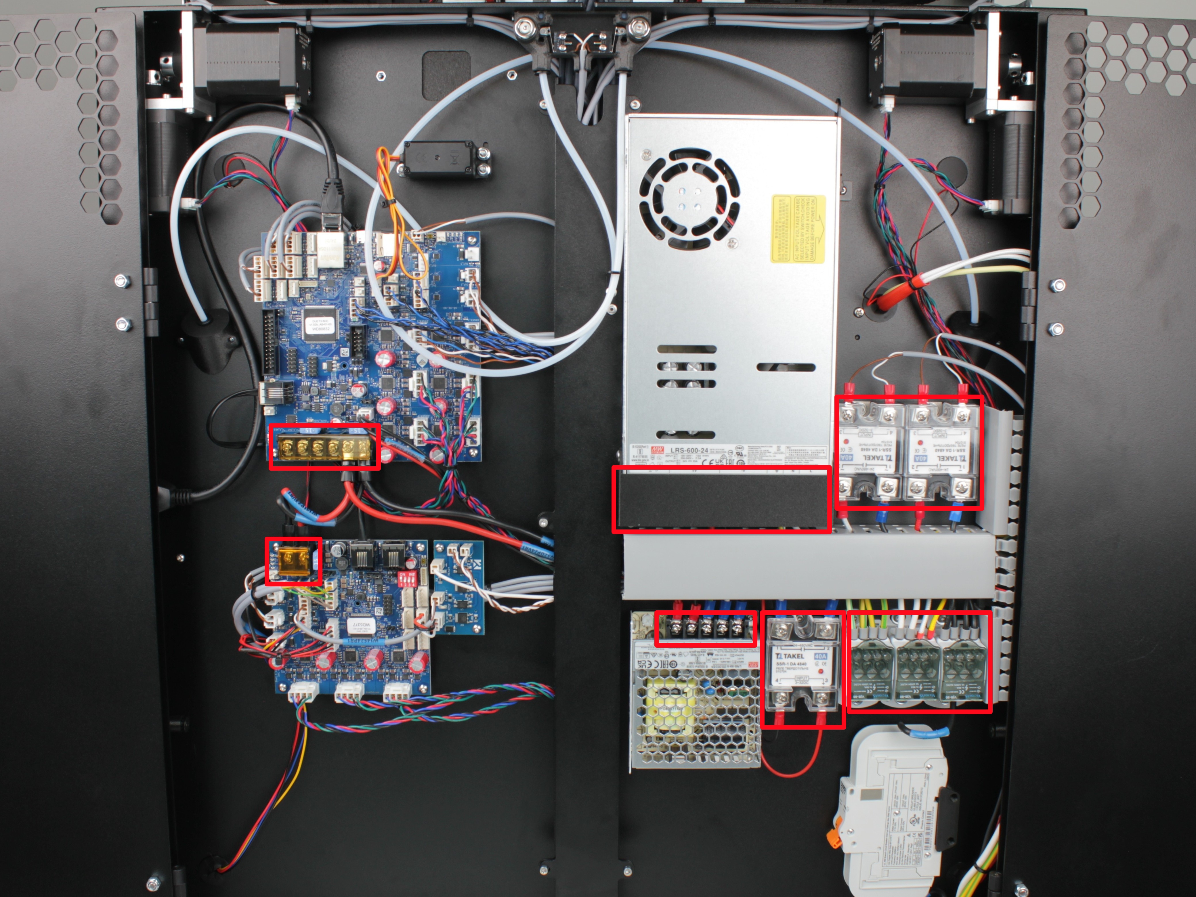
Terminal blocks with red markings indicate locations where screws need to be tightened.
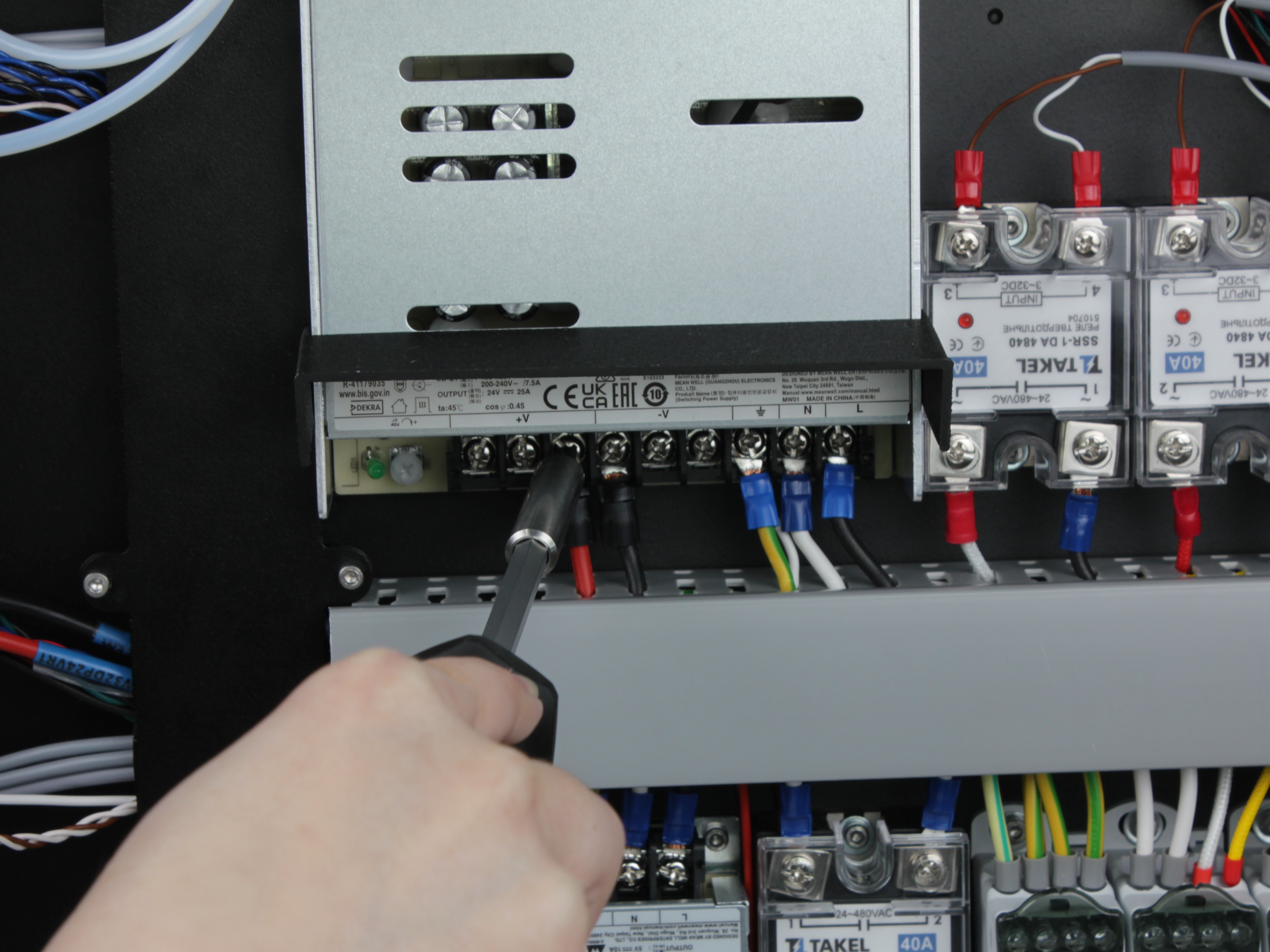
Example of proper screw tightening procedure on power supply terminal block.
-
Z-Probe & Servo Screws - Check the tightness of all screws in the Z-probe assembly and its servo drive:
- the screws fastening the magnets to the probe;
- the screws fastening the magnets to the probe holder;
- the screws holding the microswitch inside the probe;
- the screws fastening the servo to its housing.
Tighten any screw that has worked loose.
- Linear Rail Screws - Check that the rail mounting screws are tight, and tighten any that have worked loose.
Support
If you could not find an answer here, reach out to our support team.