Pressure Advance
Tune Pressure Advance to fix seam bulges, gaps and rounded corners: edit the right M572 nozzle branch per toolhead, then confirm with a test print.
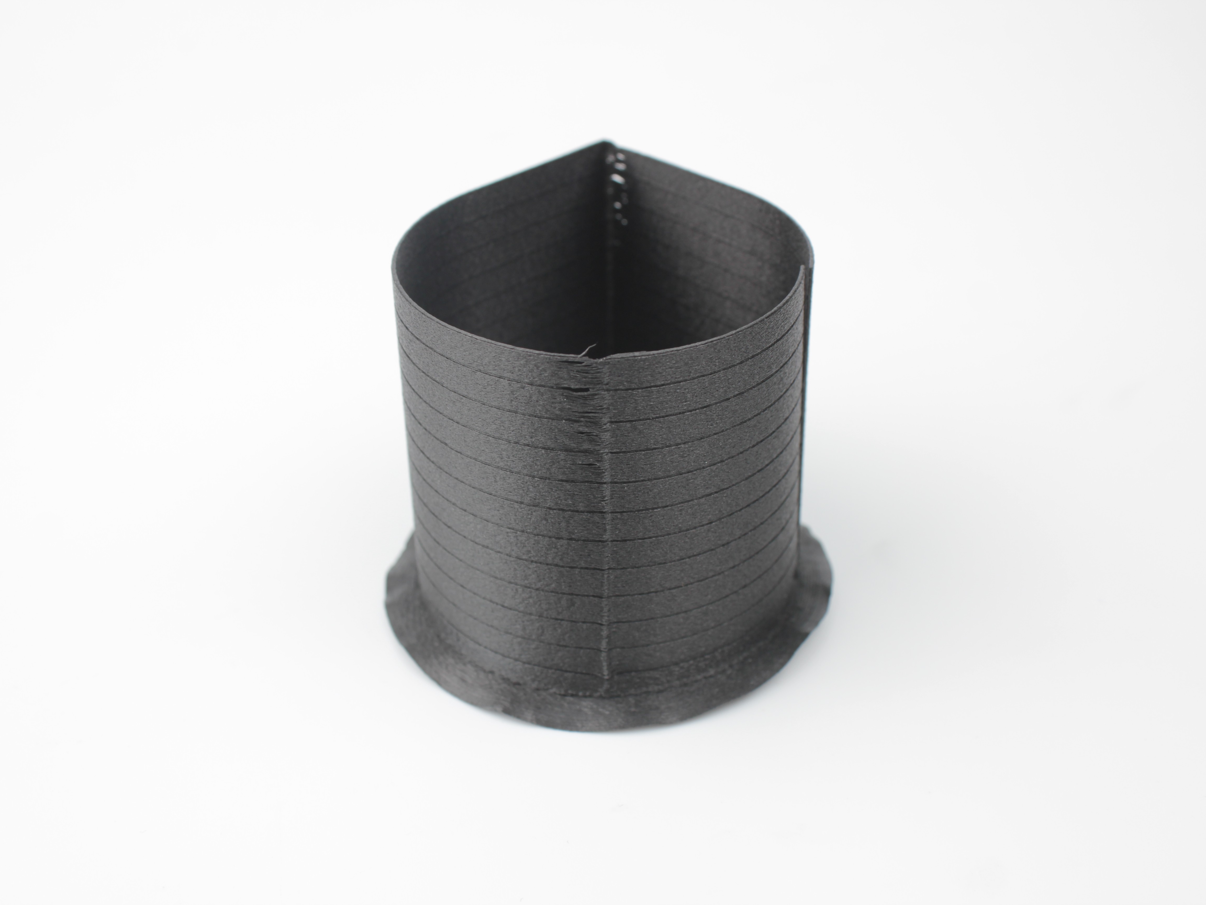
Pressure Advance is a firmware feature that compensates for filament elasticity and flow dynamics within the hotend. Properly tuning Pressure Advance improves print quality, particularly regarding sharp corners and the appearance of the print seam.
This guide explains how to understand, adjust, and calibrate the Pressure Advance setting for your Vision Miner 22IDEX V4 using PrusaSlicer. The goal is to fine-tune extrusion behavior to achieve sharper corners and minimize seam artifacts (bulging or gaps). While we provide well-tested default values in our PrusaSlicer profiles (optimized for a 0.4 mm nozzle), factors like nozzle diameter and filament moisture content can necessitate adjustments for optimal results.
Before you begin - safety and risk
Read the Safety - Before You Begin article to understand the hazards involved in working on the Vision Miner 22IDEX V4 - including electrical, thermal, mechanical, and chemical risks. All procedures in this wiki are provided as recommendations only. By choosing to follow any procedure, you do so at your own risk.
Working Principles
At its core, you can think of Pressure Advance as a smart way the printer adjusts filament flow just before speed changes, somewhat like dynamically altering retraction during a print move.
Tools & Materials
- Computer with PrusaSlicer installed
- Vision Miner 22IDEX V4 connected and operational
- Filament (the specific type you are calibrating)
- Calibration model (e.g., a simple cylinder or 20 mm cube .stl)
Pre-checks
- Before printing, run Print Check List
- Have a suitable calibration model file ready
Hot nozzle and bed
The printer's nozzle and bed can reach high temperatures. Avoid touching hot components during operation.
Step-by-Step Instructions
1. Understanding Pressure Advance Effects
Pressure Advance primarily affects two visual aspects of your print:
- Corners: Properly tuned Pressure Advance results in sharp, well-defined corners. If corners are rounded, Pressure Advance might be too high. If corners have excessive bulging or overshoot, it might be too low.
- Seam: The seam is where the printer starts and stops extrusion on each layer.
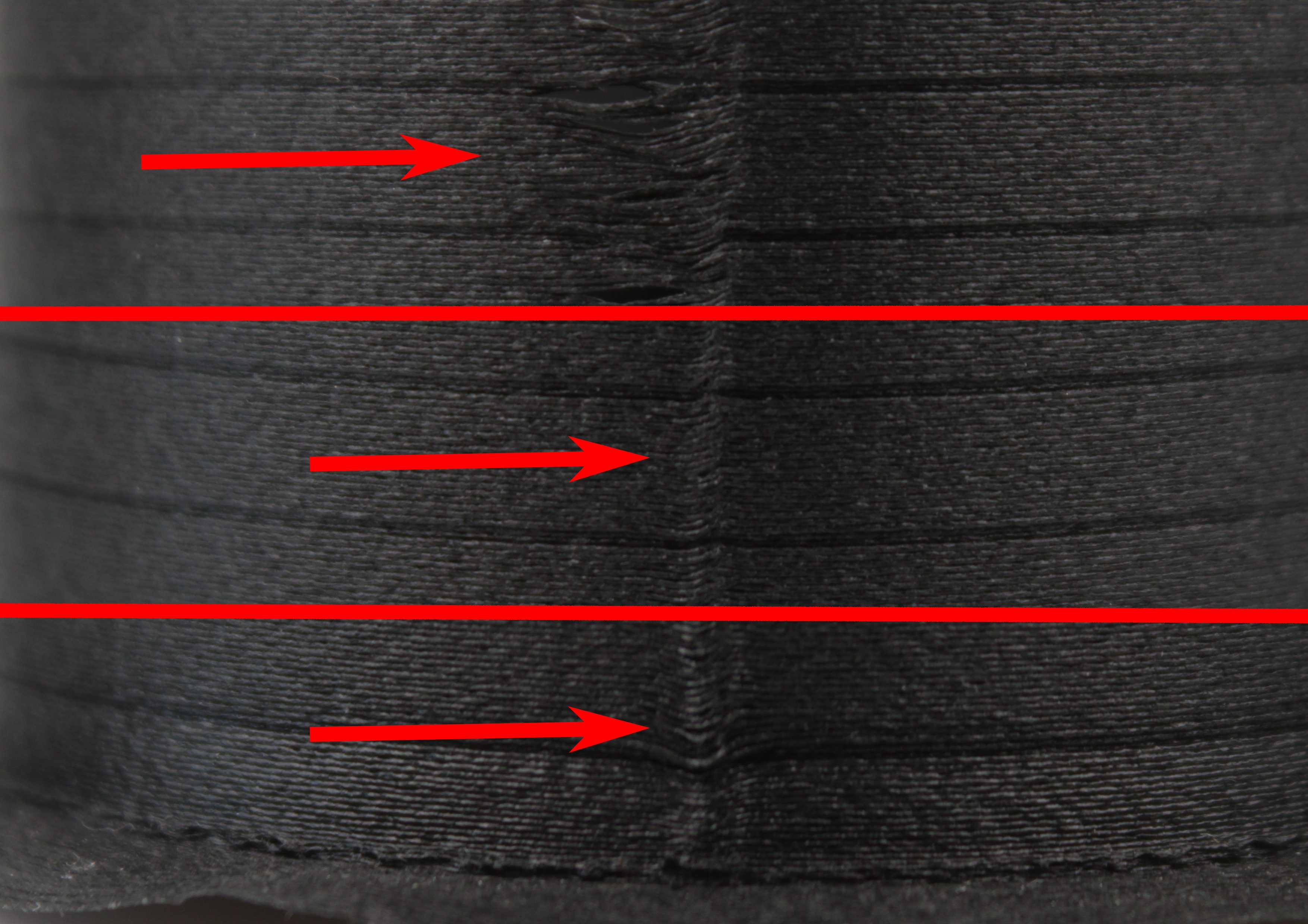
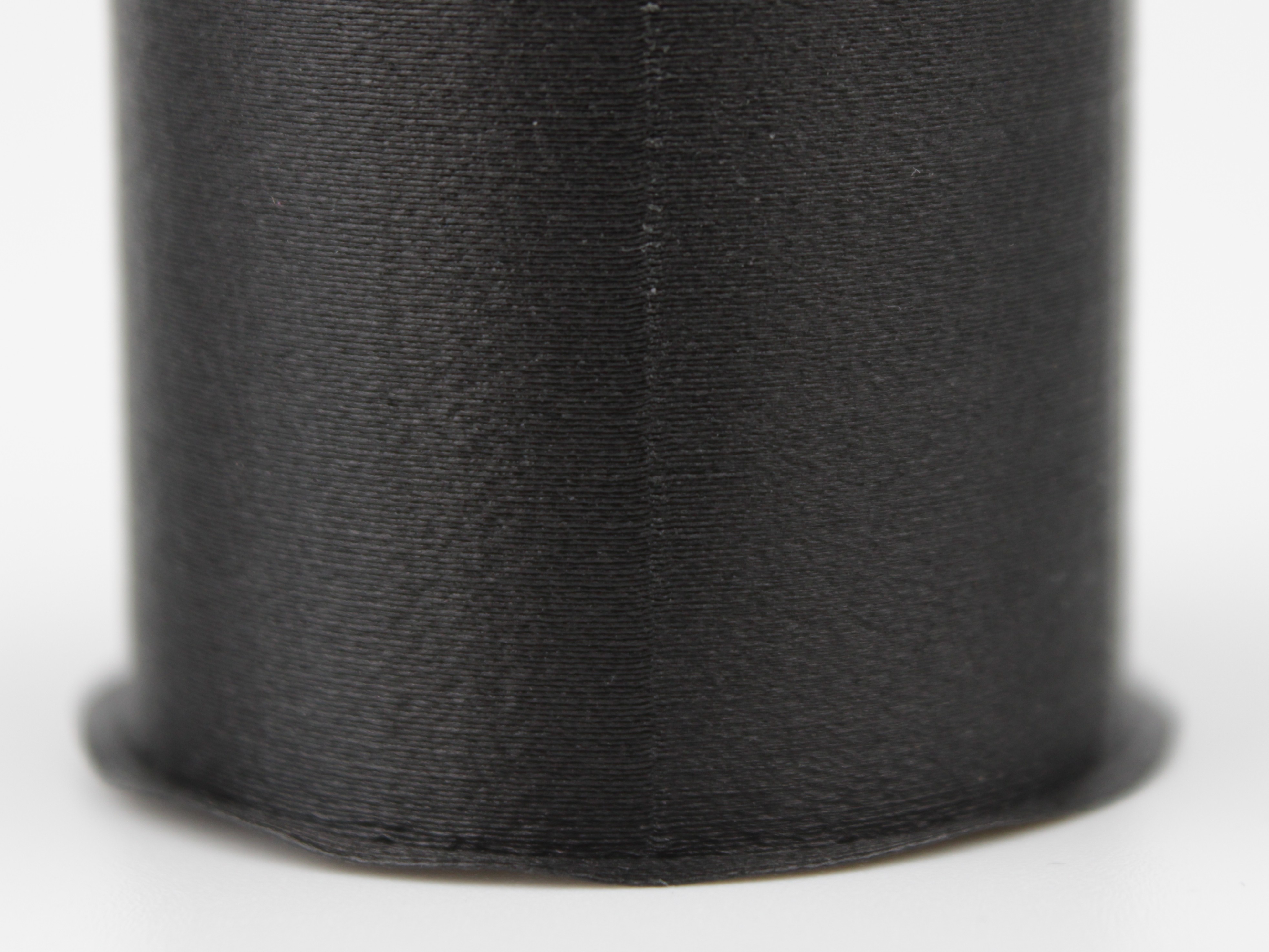
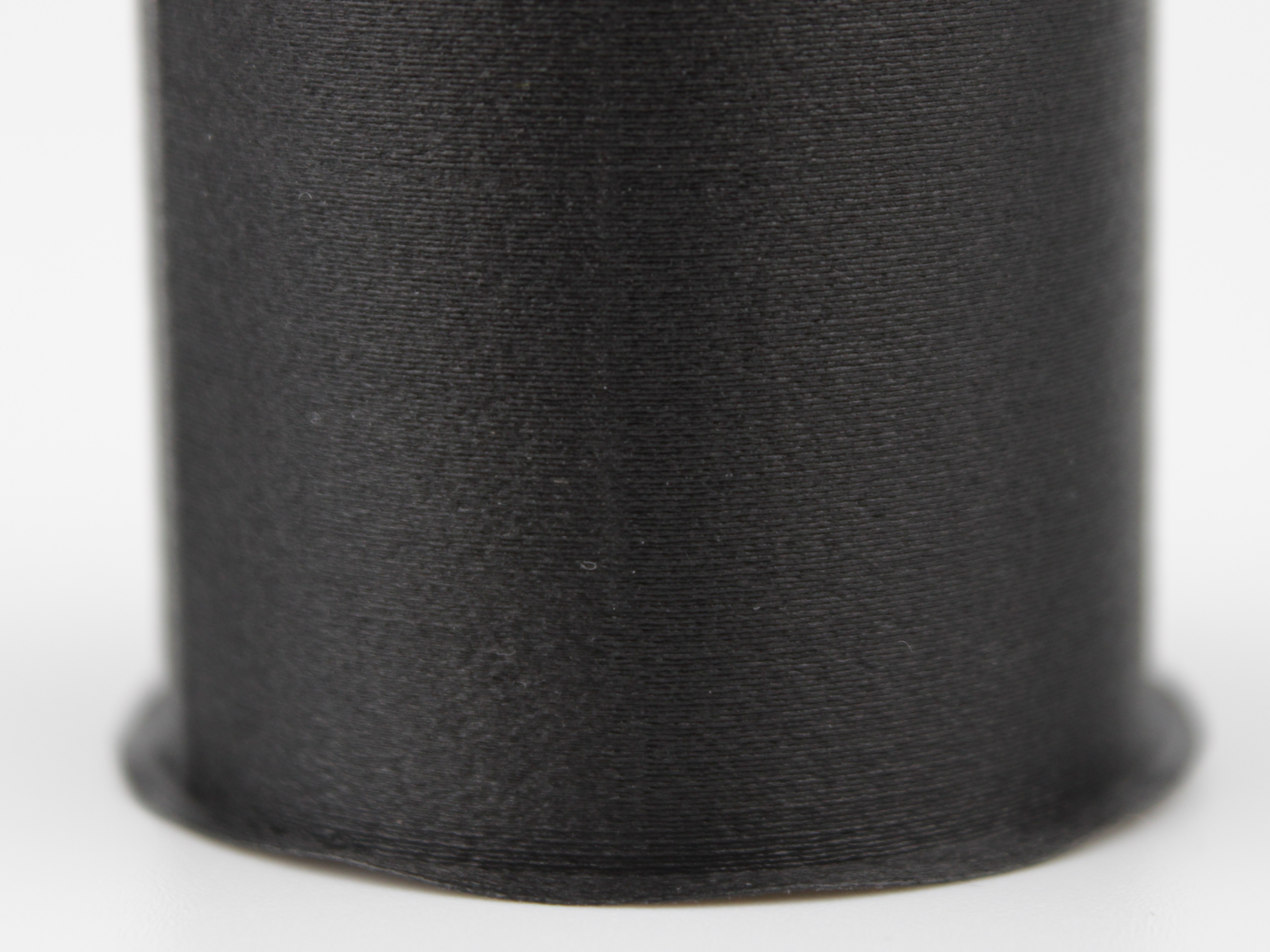
- If the seam bulges outward significantly from the print surface, Pressure Advance is likely too low (or off), causing excess pressure release at the layer end.
- If there is a gap or depression at the seam, Pressure Advance might be too high, retracting too aggressively before the layer change.
2. Locating the Pressure Advance Setting in PrusaSlicer
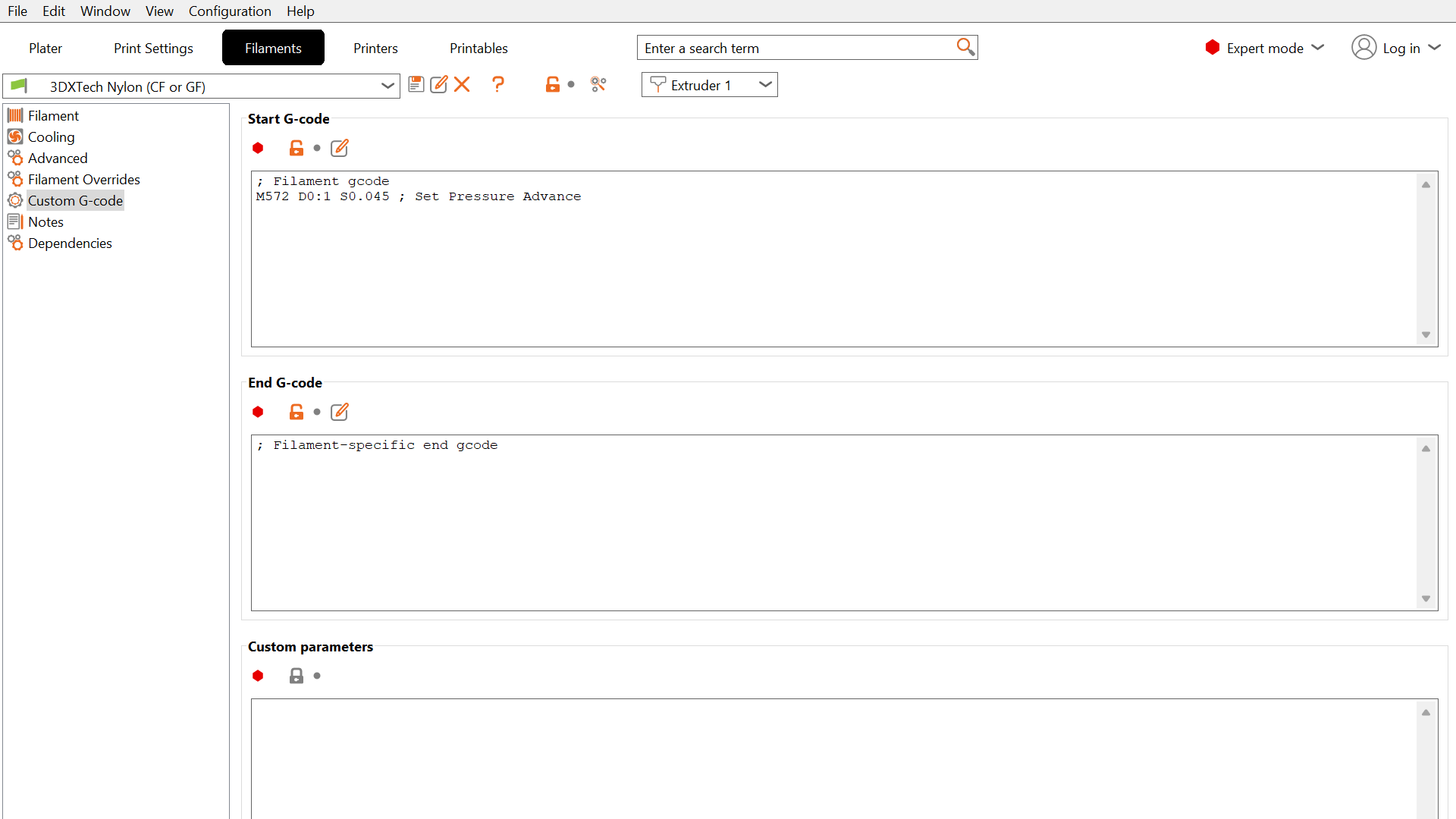
The Pressure Advance value is set via custom G-code within the filament profile:
- Open PrusaSlicer.
- Go to the Filament Settings tab.
- Select the filament profile you wish to adjust from the dropdown menu.
- Navigate to the Custom G-code section in the left-hand panel.
- Locate the Start G-code text box.
- Look for a line starting with
M572, for exampleM572 D0:1 S0.045. This command sets the Pressure Advance value. The number afterSdiffers from profile to profile, so do not expect the same value in every filament. If the line is not present, the printer will use its firmware default or none if not configured.
3. Baseline Values and Adjusting for Nozzle Size
Our default profiles often use a Pressure Advance value suitable for common materials with a 0.4 mm nozzle.
- Default (0.4 mm Nozzle): A typical starting value for many plastics (like PLA, ABS) is
S0.035. - Larger Nozzles (0.6 mm): Pressure effects are less pronounced with larger orifices. You should decrease the Pressure Advance value significantly. Try starting around
S0.01or even disabling it completely by setting it toS0.0. - Very Large Nozzles (0.8 mm and up): It is generally recommended to disable Pressure Advance entirely for very large nozzles - set to
S0.0.
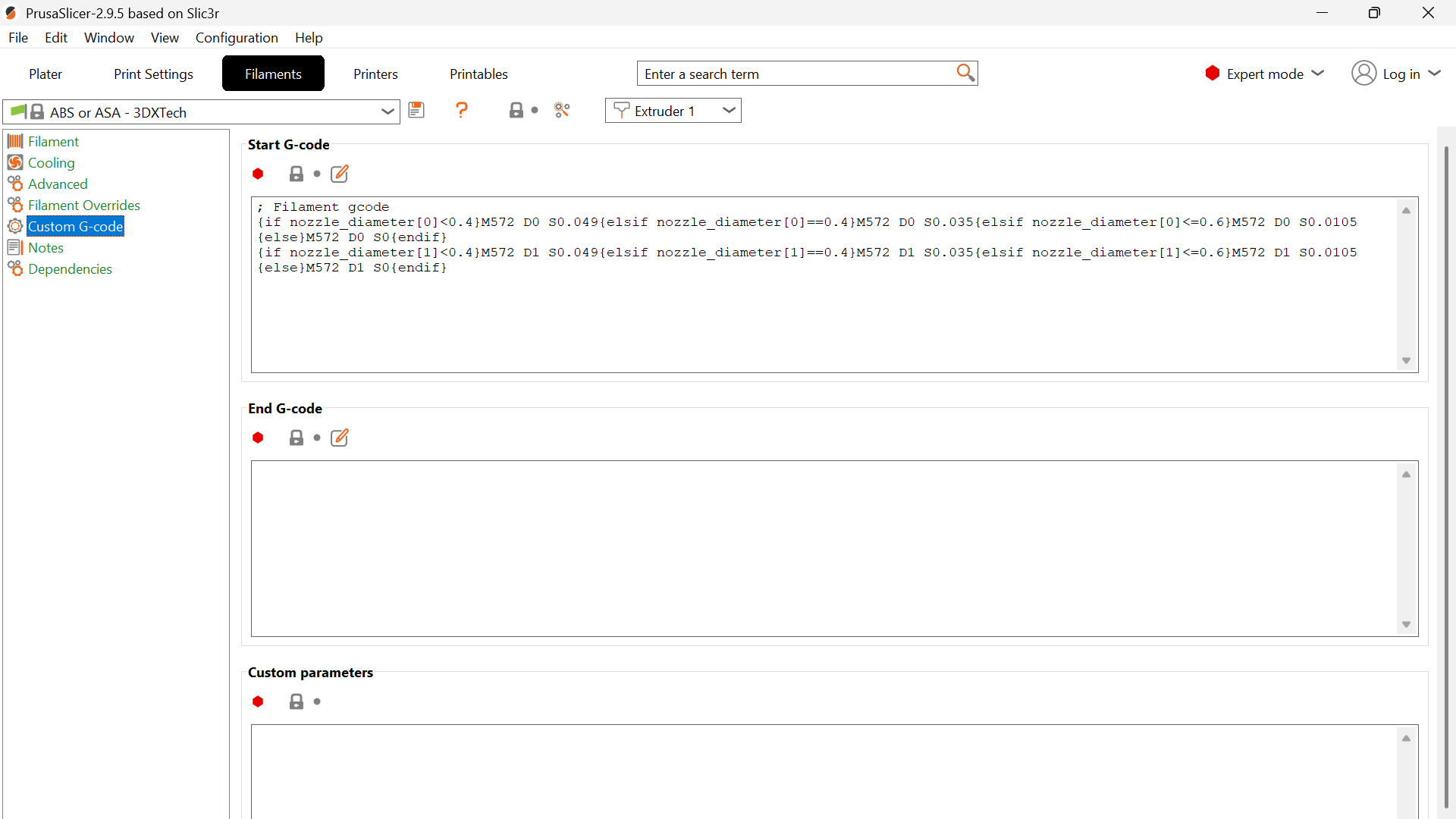
Our profiles already do this selection for you. Instead of a single M572 line, they carry a conditional expression that reads the nozzle diameter and picks the matching value, so the same profile stays correct when you swap nozzles:
Reading the conditional, and editing the right part of it
This is where people get it wrong, so it is worth slowing down. The expression is two lines, one per toolhead, and each line contains four alternatives, one per nozzle size. It looks dense, but it is only saying "look at which nozzle this toolhead has, and use the matching number".
{if nozzle_diameter[0]<0.4}M572 D0 S0.049{elsif nozzle_diameter[0]==0.4}M572 D0 S0.035{elsif nozzle_diameter[0]<=0.6}M572 D0 S0.0105{else}M572 D0 S0{endif}
{if nozzle_diameter[1]<0.4}M572 D1 S0.049{elsif nozzle_diameter[1]==0.4}M572 D1 S0.035{elsif nozzle_diameter[1]<=0.6}M572 D1 S0.0105{else}M572 D1 S0{endif}
Decoded, each line means:
| Nozzle on that toolhead | Value applied | Where it sits in the line |
|---|---|---|
0.2 mm (anything under 0.4) | S0.049 | first branch, after {if ...<0.4} |
0.4 mm | S0.035 | second branch, after {elsif ...==0.4} |
0.6 mm | S0.0105 | third branch, after {elsif ...<=0.6} |
0.8 mm (anything larger) | S0 (disabled) | last branch, after {else} |
And the two addresses you need to keep straight:
D0is the left toolhead (Tool 0),D1is the right one (Tool 1). The first line handles D0, the second handles D1.nozzle_diameter[0]and[1]are the nozzle sizes of those same two toolheads, taken from your printer profile.
Change the branch that matches your nozzle, and nothing else
The most common mistake here is editing the wrong branch. If you run a 0.4 mm nozzle and change the number after {elsif ...<=0.6}, you have just retuned the 0.6 mm case: your print behaves exactly as before, and the next time you fit a 0.6 nozzle it will misbehave for no apparent reason.
Before you change anything, check two things. Which nozzle is actually fitted to the toolhead you are tuning, and which line that toolhead is on, D0 for left or D1 for right. Then change only the S value inside the matching branch, leaving the surrounding {if} / {elsif} conditions untouched.
If you run different nozzle sizes on the two heads, remember that each line is independent. Tuning the left head does nothing for the right one.
Disabling Pressure Advance requires explicit command
To disable Pressure Advance, you must explicitly set the value to zero using the G-code command: M572 S0.0. Simply deleting the M572 line from the custom G-code will cause the printer to revert to its built-in firmware default (which might be 0.035 or another non-zero value), not disable it.
4. Calibration Procedure
Finding a value: the Pressure Advance test
Do not guess your way there one print at a time. Use the dedicated test in Material Tuning. It prints a teardrop shape where the Pressure Advance value climbs from bottom to top, so the transition from blobs to gaps is visible in a single part and you can read the best value straight off it.
For most materials the useful range is roughly 0 to 0.15, and the test sweeps across it. Take the value you read off the print and put it into the matching branch of the conditional described above.
The test file carries its own temperatures
The calibration file ships with default cooling, bed, nozzle, and chamber temperatures. Those defaults are not right for every filament. Before printing the test, check them against the material you are actually testing, otherwise you will be calibrating Pressure Advance against a print that is failing for unrelated reasons.
Confirming the value: print a cube
Once the test gives you a number, verify it on a shape that shows both failure modes at once. A simple cube is ideal, because it gives you two things to judge:
- The corners, where the nozzle changes direction sharply. This is where too little compensation causes overshoot and bulging.
- The seam, where each layer starts and ends. This is where too much or too little compensation is easiest to see.
Position the seam in the middle of a wall rather than on a corner. On a corner the seam hides in the geometry; in the middle of a flat face you can see exactly what it is doing. In PrusaSlicer this is Print Settings > Layers and perimeters > Seam position.
Print the cube with your candidate value in the M572 branch for the nozzle you are using, then judge it against the criteria below.
- Evaluate: Carefully examine the corners and the seam of the printed model.
- Seam Bulging / Overshooting Corners? → Pressure Advance might be too low. Increase the
Svalue slightly (e.g., from 0.035 to 0.045). - Seam Gap / Rounded Corners? → Pressure Advance might be too high. Decrease the
Svalue (e.g., from 0.035 to 0.010, or from 0.01 to 0.0 for larger nozzles).
- Seam Bulging / Overshooting Corners? → Pressure Advance might be too low. Increase the
Use dedicated calibration models for faster iteration
Use a calibration model for Pressure Advance tuning (like a cylinder or square) for faster iteration cycles.
- Iterate: Modify the
M572 S<value>in the filament's start G-code, re-slice, and print again. - Save Profile: Once satisfied, save the modified filament profile.
Ready-made calibration files
You do not have to model the cube yourself. These are the files we use, already set up with the seam placed for inspection:
| File | Format | Use it when |
|---|---|---|
| pressure_advance_tuning.gcode | .gcode | Finding the value. Sweeps the range in one print. A copy also ships on the printer under Files > Jobs > Test Prints, so you can run it without downloading anything. |
| Verification cube, project (TODO: upload to R2 and link) | .3mf | You want to re-slice with your own material and nozzle. |
| Verification cube, ready to print (TODO: upload to R2 and link) | .gcode | Sliced for a 0.4 mm nozzle, 0.2 mm layers, Tool 0, ABS/ASA. Only use it if that matches your setup. |
The ready-sliced G-code is material and nozzle specific
The .gcode version is already sliced for a 0.4 mm nozzle at 0.2 mm layer height on Tool 0 with ABS or ASA. If any of that does not match your machine or filament, start from the .3mf project and slice it yourself. Printing G-code sliced for a different setup wastes the run at best.
Troubleshooting
FAQ
Support
If you could not find an answer here, reach out to our support team.