Motion System Adjustment
Fix first-layer height that varies across the bed: read a cold Height Map, straighten crossbar bow along X and shim the Y rails to under 0.25 mm.
If the first layer varies across large prints – especially different Z on the left vs. right – run auto-calibration first. If the mesh still shows bow along X or corner twist that looks like Y rail parallelism, use this guide: capture a cold mesh on glass, read the Height Map, then adjust the crossbar and Y rails in a controlled order.
Before you begin - safety and risk
Read the Safety - Before You Begin article to understand the hazards involved in working on the Vision Miner 22IDEX V4 – including electrical, thermal, mechanical, and chemical risks. All procedures in this wiki are provided as recommendations only. By choosing to follow any procedure, you do so at your own risk.
Pinch and tip hazards while deflecting the crossbar
Do not trap fingers between the crossbar, plate, and tools. If you use the "screwdriver on the bed" method, move Z slowly and keep hands clear.
Tools and Materials
- Glass Build Plate – brand-new or perfectly clean
- 2.5mm HEX screwdriver (hex wrench)
- Microfiber cloth (or other lint-free cleaning cloth)
- H-Assembly Shims Set for Y-rail corners if needed – request through support
- Height Map plugin enabled (see Visualizing the Mesh)
1. Run the test
- Stabilize temperature – work at stable ambient temperature; bed cold for this procedure.
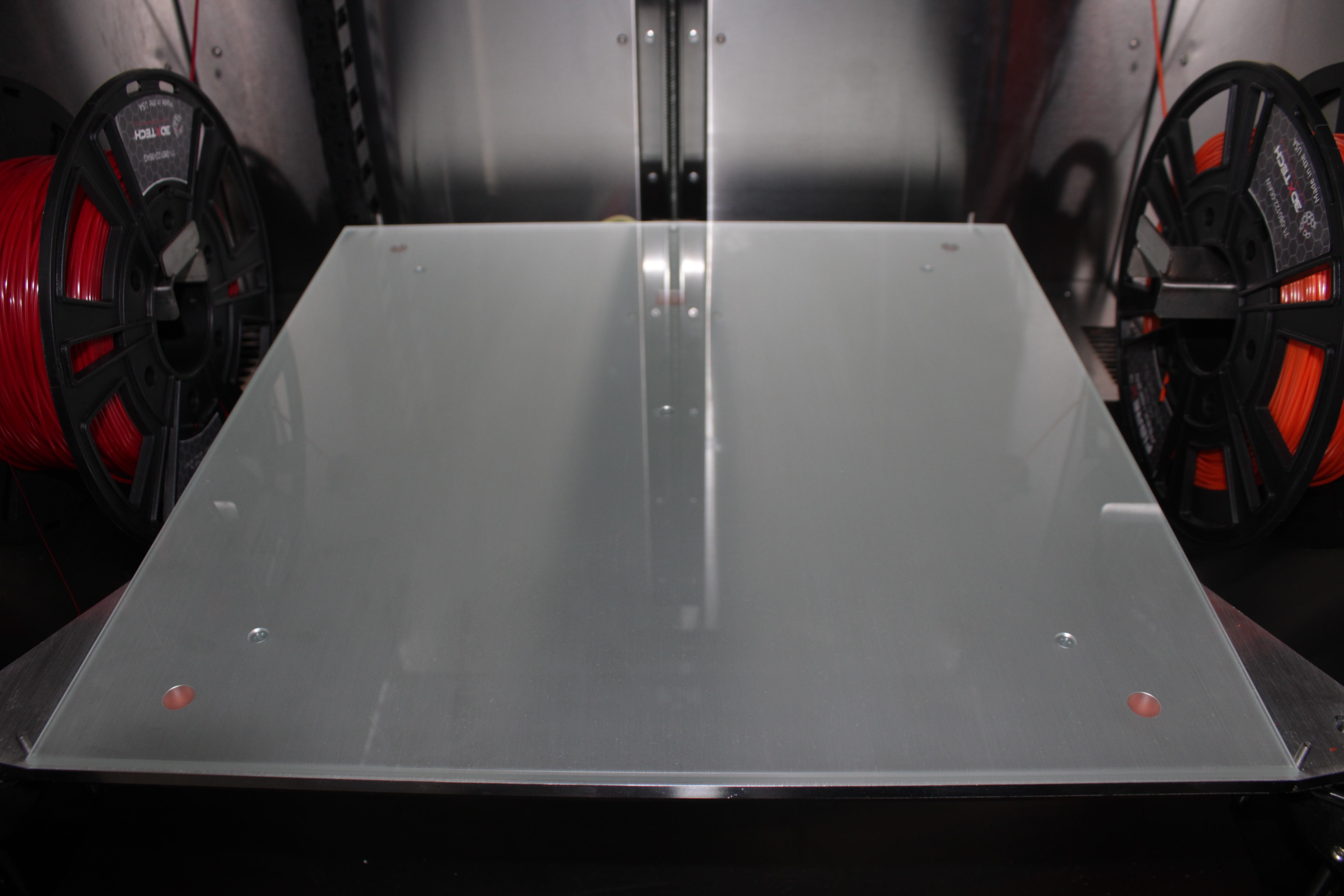
- Prepare the build plate – clean the aluminum plate, lay a clean glass plate on top, and do not thumbscrew it tight (clamping can distort the stack).
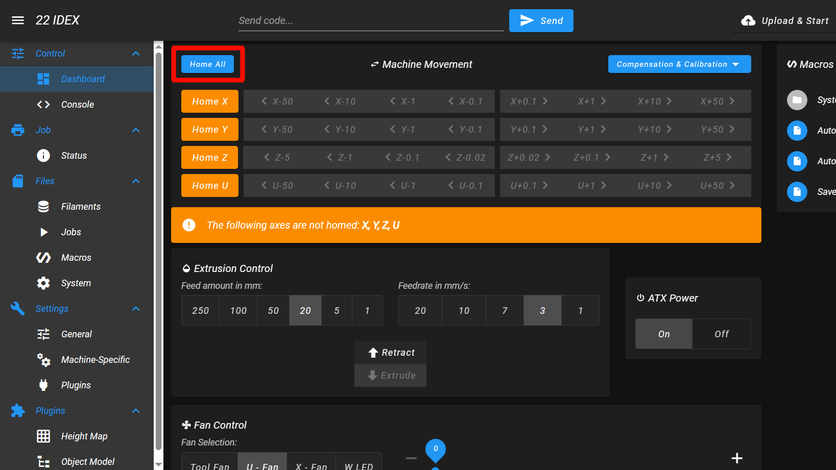
- Home all axes – in the Web Interface Dashboard, press Home All.
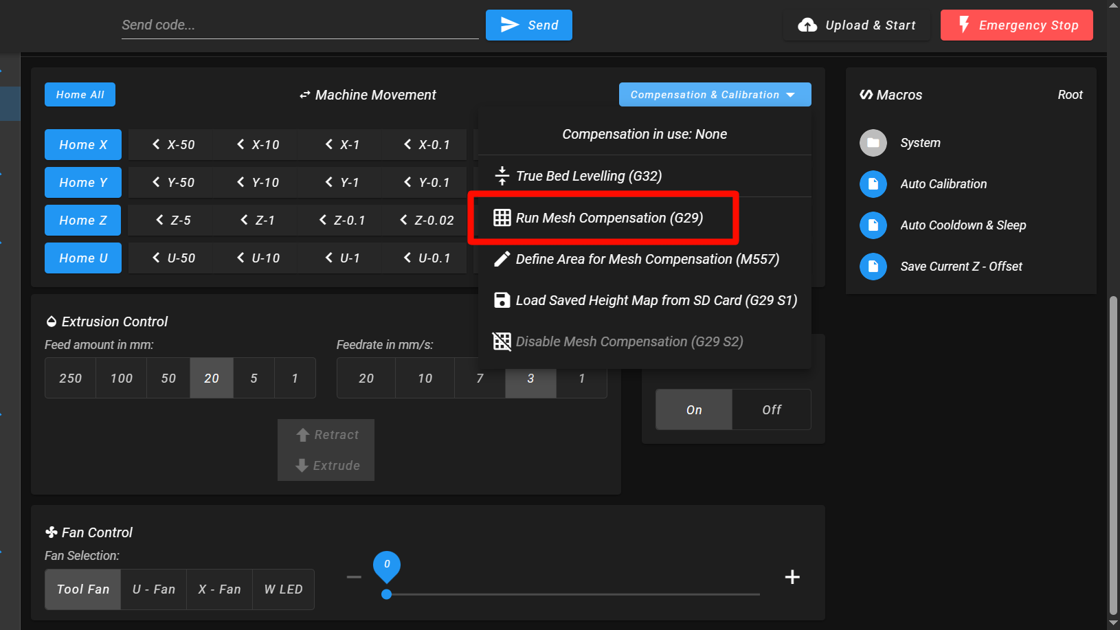
- Run mesh compensation – in Compensation & Calibration, press Run Mesh Compensation (G29) (or send
G29in Console).
2. Visualizing the mesh
- Plugins – enable the Height Map plugin.
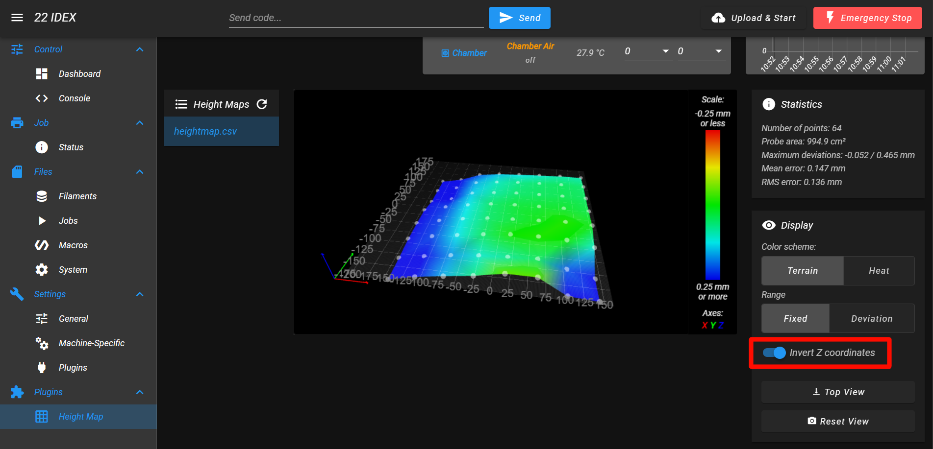
- Height Map tab – open the last mesh; enable Invert Z coordinates so high/low reads match how you think about crossbar bow.
3. Analyzing the mesh
- Keep Invert Z coordinates on.
- X straightness – along X, the trace should be straight (tilt is OK; bow is not).
- Y parallelism – compare front vs. back rail corners; skewed corners often mean Y rails are not parallel.
If X shows bow, continue to Adjusting the X-axis straightness. If X is straight, jump to Adjusting the Y-axis parallelity.
4. Adjusting the X-axis straightness
Goal: remove concave / convex bow along X by manually straightening the crossbar while the left Y-rail attachment is slightly loose.
The screenshot below shows a slight bow that can be corrected using this method.
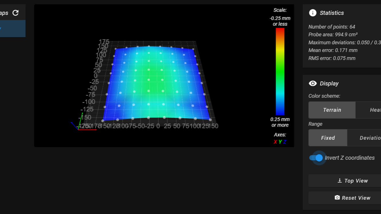
- Read the mesh – decide if the crossbar center needs up or down deflection.
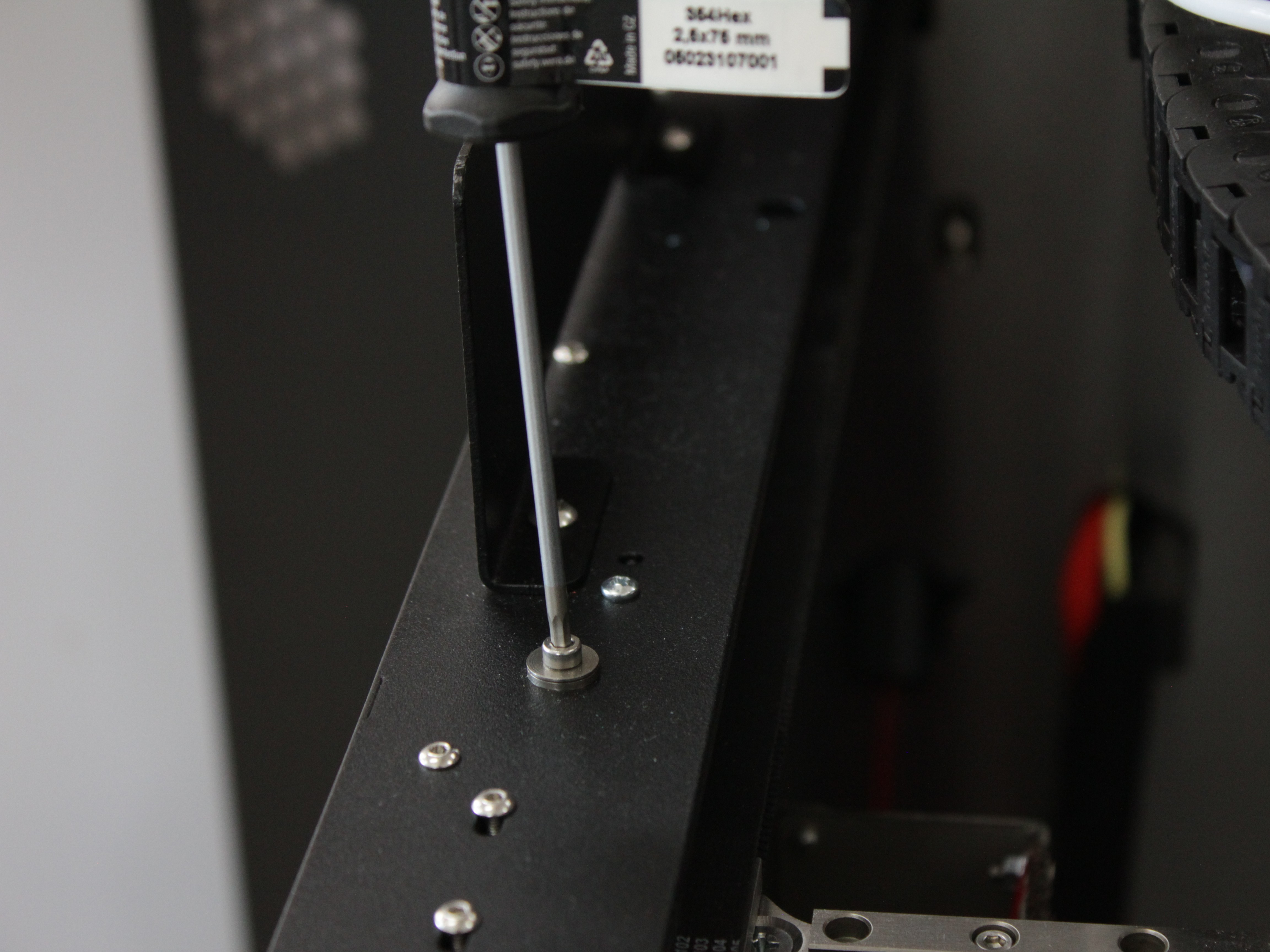
- Loosen left Y-rail to top gantry screws (front and back pair on the left side only) about 1/2–1 turn so the crossbar can flex. You need to loosen two screws: the front one shown in the image below, and another screw located further back – you can identify it by the thick washers underneath.
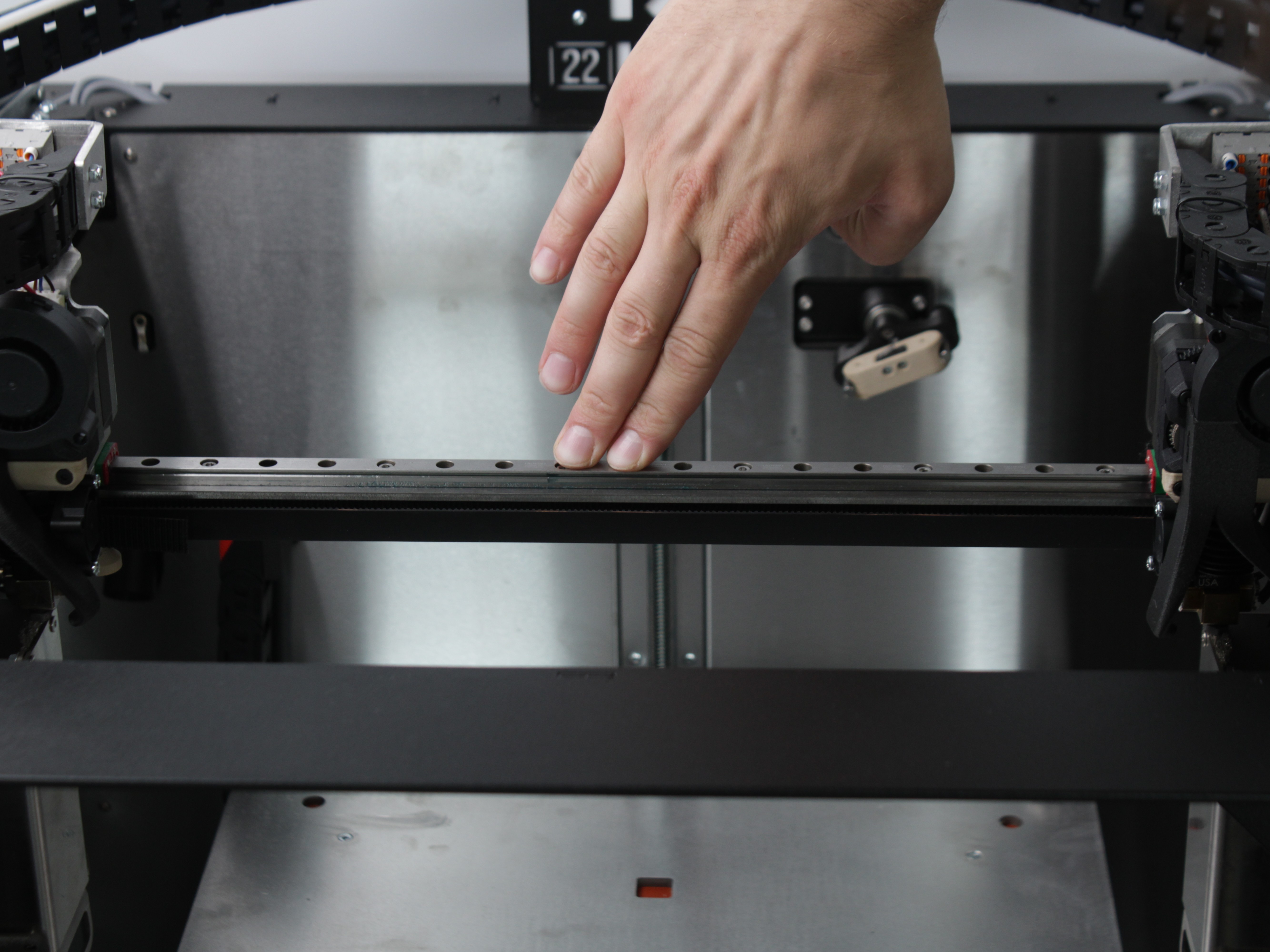
- Straighten the crossbar by hand – apply gentle pressure to correct the bow; overshoot slightly (example: ~1 mm bow may need a few mm deflection).
- Re-tighten left Y-rail to gantry – tighten back screw first with gantry toward the rear, then front screw with gantry forward; respect any locator hole first if your frame uses one.
- Re-probe – Home All,
G29, re-open Height Map and confirm X is straight; repeat if needed.
5. Adjusting the Y-axis parallelity
Use this after X is acceptable.
The screenshot below shows corner height differences that indicate a Y-rail parallelism issue.
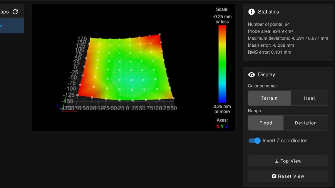
- Home All and run
G29again. - Inspect left/right corners with invert-Z still on.
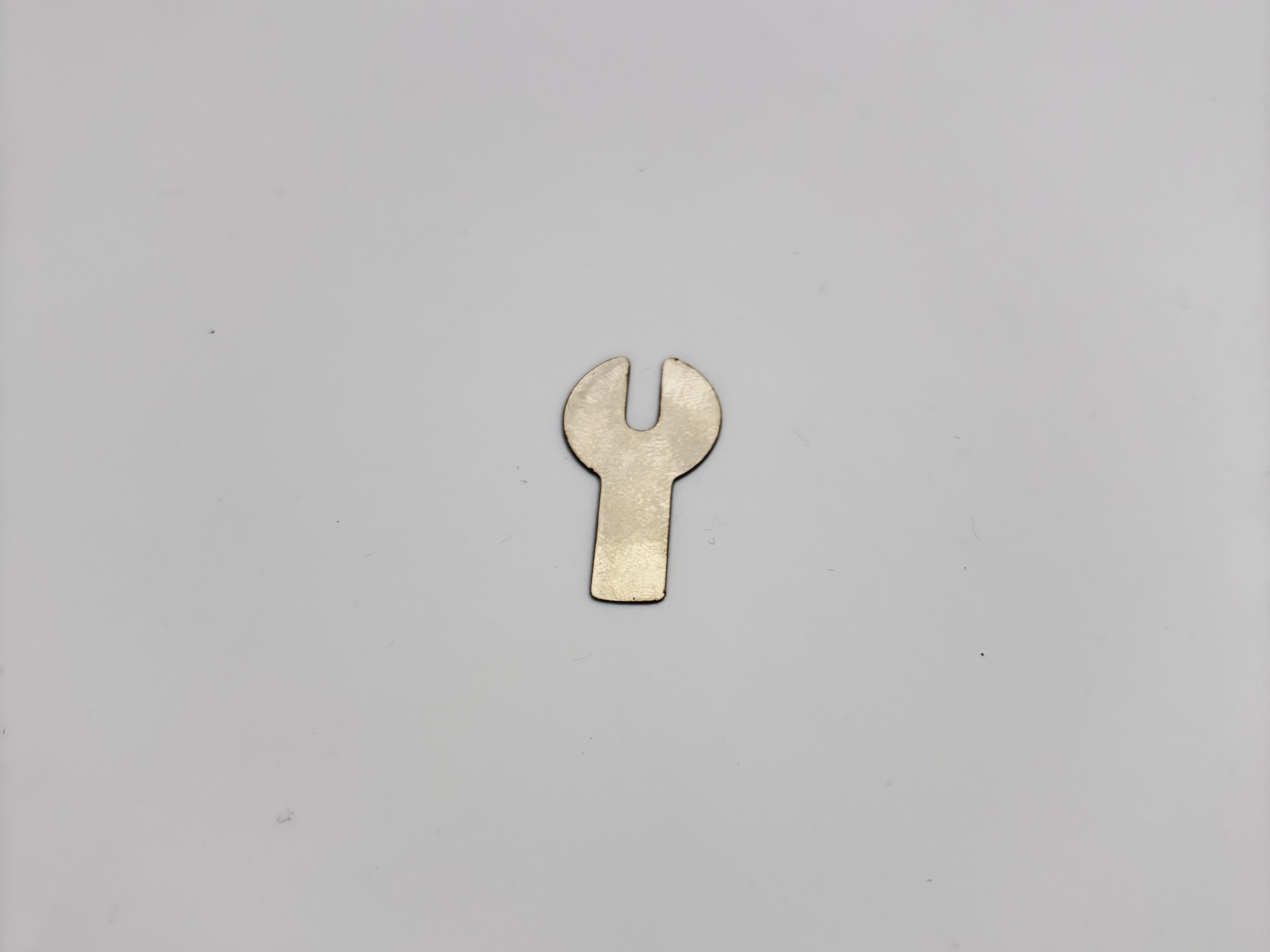
- Shim between top gantry and Y-rail spacers if one corner is consistently high vs. the opposite corner on the same side. The H-Assembly Shim is a thin 0.2 mm washer:
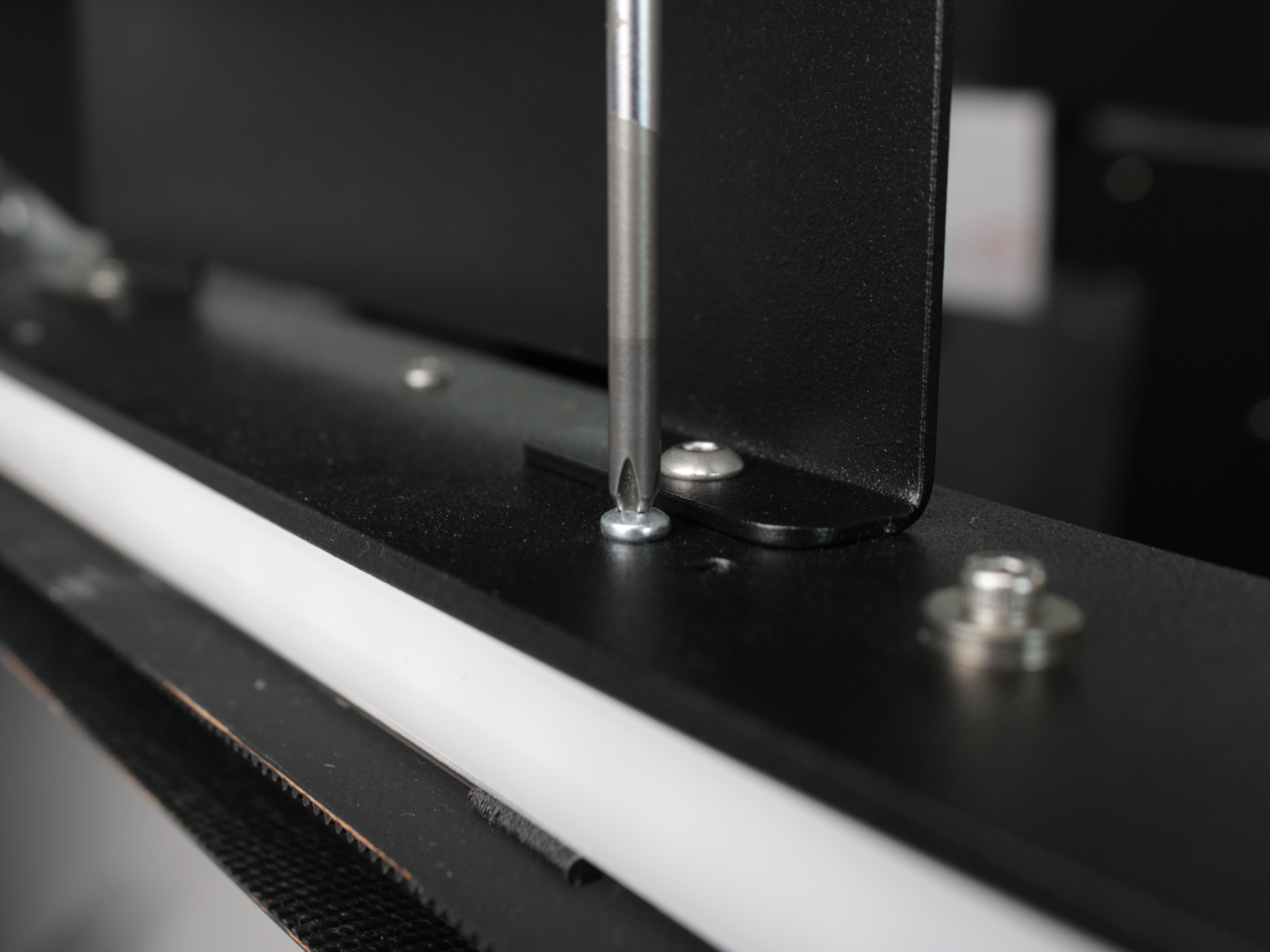
- Loosen the Y-rail LED clip screw about 1/2 turn to release the clip.
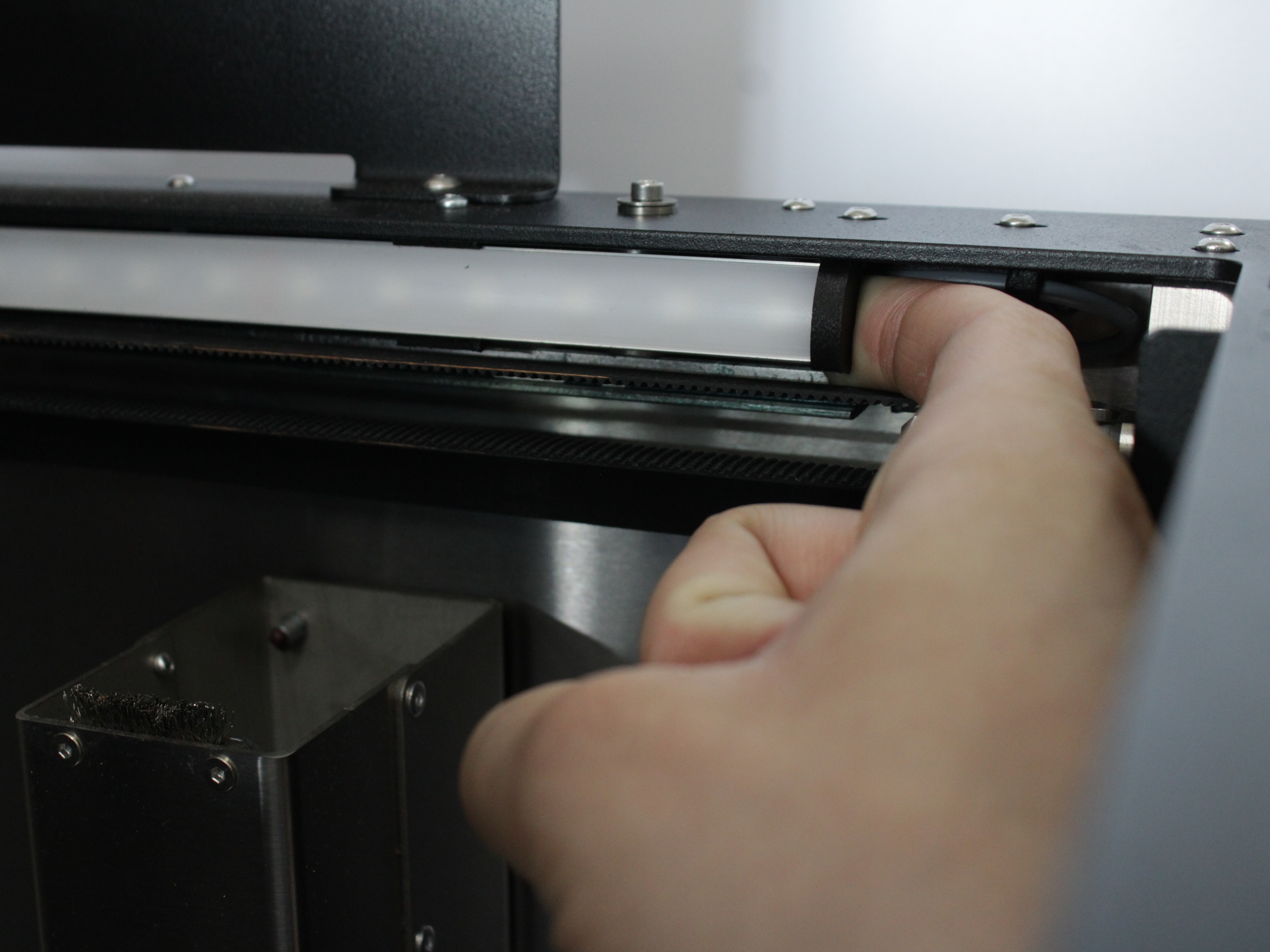
- Remove the LED from the clip by hand – the crossbar cylinder becomes visible.
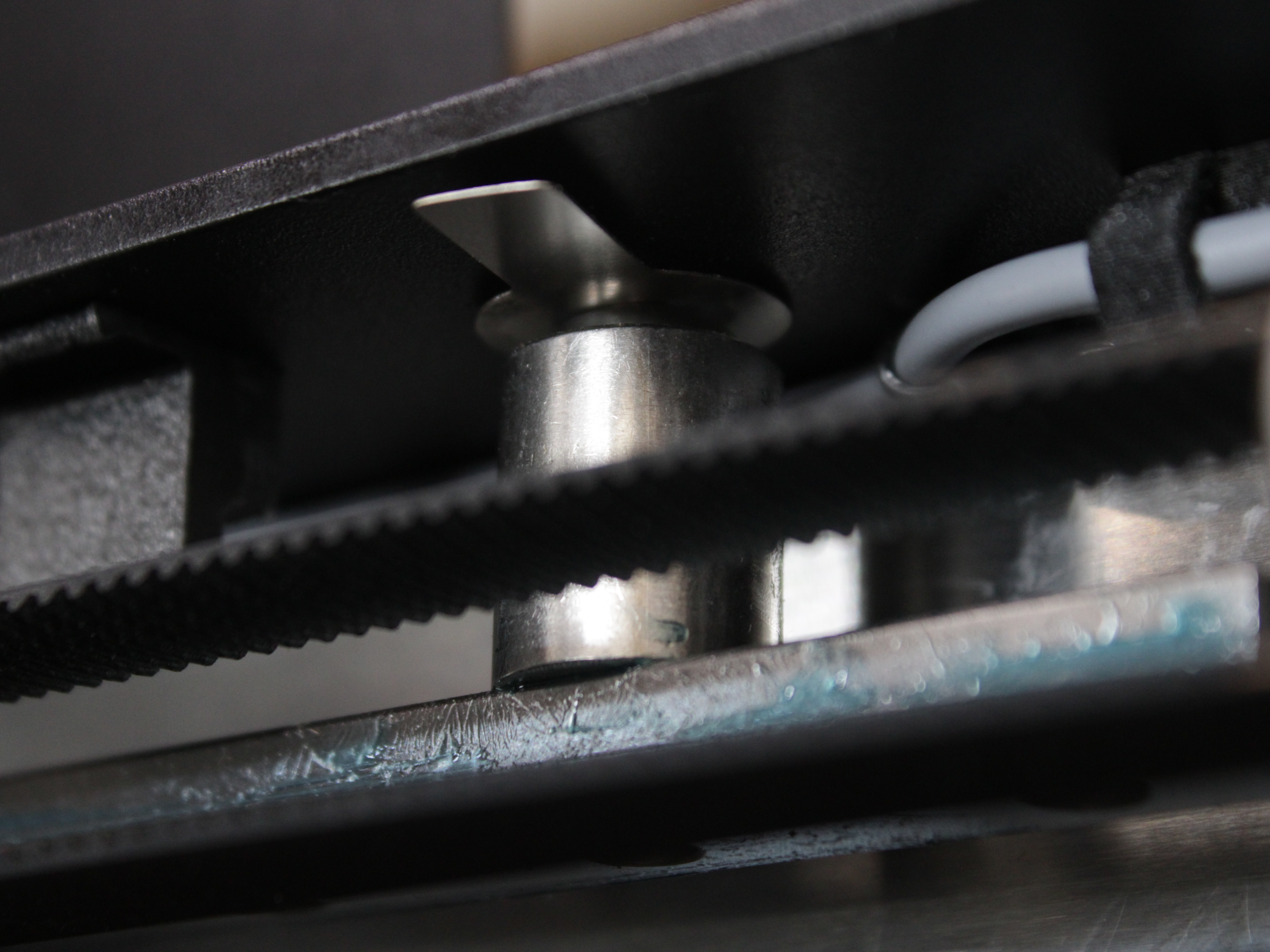
- Loosen the crossbar cylinder screw about 1/2 turn so you can insert the shim.
- Insert the shim under the crossbar cylinder.
Shim thickness
Start with thin shims and re-probe after each small change. Large jumps can over-correct.
- Re-tighten the crossbar cylinder screw, reinstall the LED in the clip, and tighten the clip screw.
- Home All,
G29, confirm the mesh improved.
Verifying the Result
After completing the adjustments, open the Height Map and check the following:
- The height map should be relatively uniform across the entire bed
- The difference between the highest and lowest points should be no more than 0.25 mm
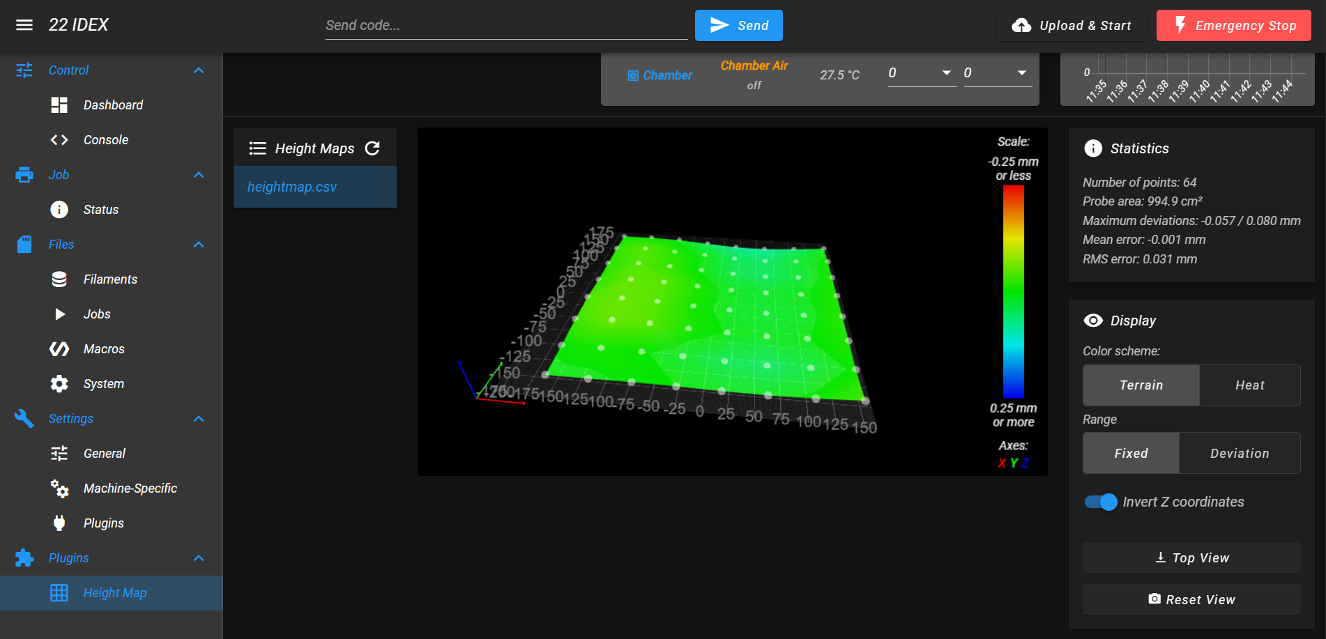
If the deviation is still greater than 0.25 mm, repeat the relevant adjustment section (X-axis straightness or Y-axis parallelity) as needed.
Iterative adjustment process
If you did not achieve a satisfactory result on the first attempt, repeat the calibration process. Learning to adjust the height map correctly on the first try requires significant practice – this is a complex process that demands professionalism and experience.
Frequently Asked Questions
Troubleshooting
Support
If you could not find an answer here, reach out to our support team.