Auto Calibration
Run auto calibration on the 22 IDEX V4 to set tool height, Z-offset, bed mesh and nozzle-to-nozzle XY offset, including the heat break adjustment prompt.
This guide covers the auto-calibration procedure for the Vision Miner 22IDEX V4 printer. Auto-calibration establishes precise nozzle heights, Z-offset, bed mesh compensation, and XY alignment – all in one automated sequence. Run this procedure after nozzle changes, significant maintenance, or if you suspect alignment issues.
The printer heats both nozzles and probes them against the bare aluminum bed to measure their relative positions. The full calibration sequence includes:
- Tool Height Calibration – measures the height difference between Tool 0 (left) and Tool 1 (right). The tool offset is always measured; the manual heat-break adjustment is only needed for Mirror Mode and Duplicate Mode and can be skipped.
- Z-Offset Calibration – sets the precise first-layer height for proper bed adhesion.
- Mesh Bed Calibration – probes the bed surface to create a compensation map. Runs only in Auto mesh-compensation mode; it is skipped in Manual mode, the factory default (see Bed Leveling).
- XY Auto Squaring – corrects axis perpendicularity in the XY plane, and calculates motor steps per mm when that option is enabled (runs if either is enabled).
- XY Offset Calibration – measures the nozzle-to-nozzle offset by probing a hole in the bare bed. Essential for multi-color and multi-material printing.
Before you begin - safety and risk
Read the Safety - Before You Begin article to understand the hazards involved in working on the Vision Miner 22IDEX V4 – including electrical, thermal, mechanical, and chemical risks. All procedures in this wiki are provided as recommendations only. By choosing to follow any procedure, you do so at your own risk.
YouTube media is off. Allow it in cookie settings to load this video.
Watch on YouTubeOpen on YouTube if the player does not load.
Tools and Materials
- 2mm HEX - Wera Screw Driver (hex wrench) – heat break set screw
- 2.5mm HEX - Wera Screw Driver (hex wrench, optional) – leveling the heater block during adjustment
- Hand Nozzle Brush 3-Pack (brass brush preferred) – nozzle cleaning
- High Temp Gloves (optional) – hot hardware
1. Starting the Calibration
-
Open the Dashboard in the Web Interface.
-
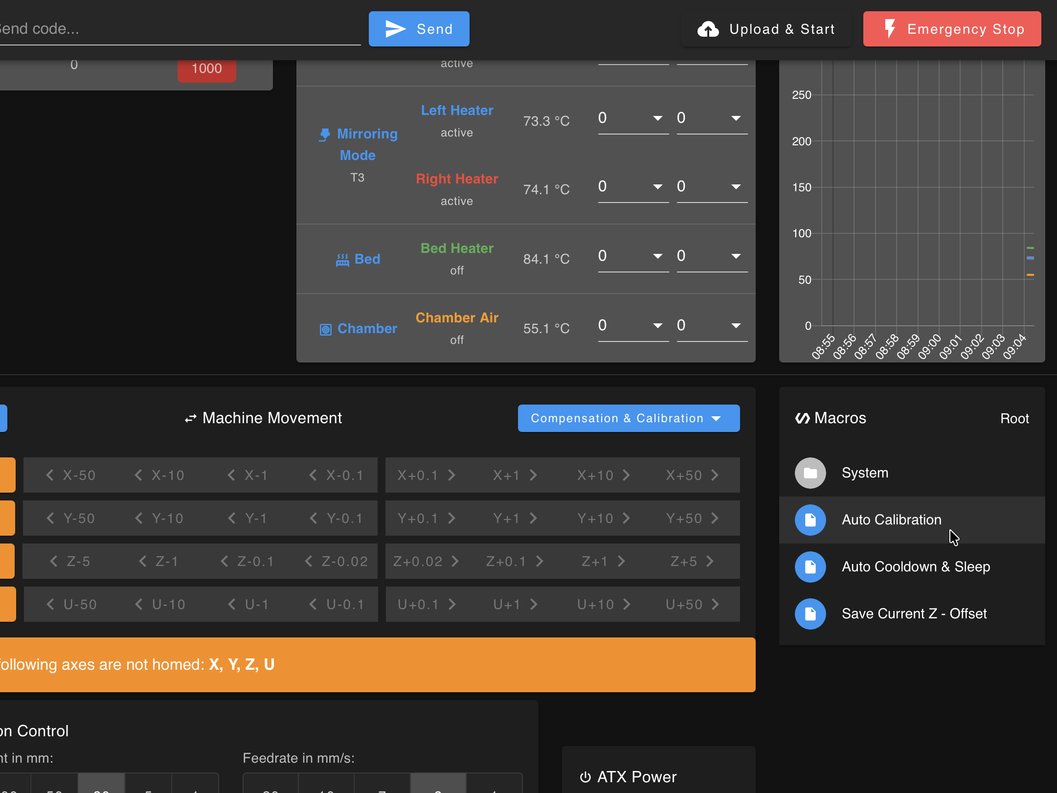
Open the Macros panel and select Auto Calibration.
-
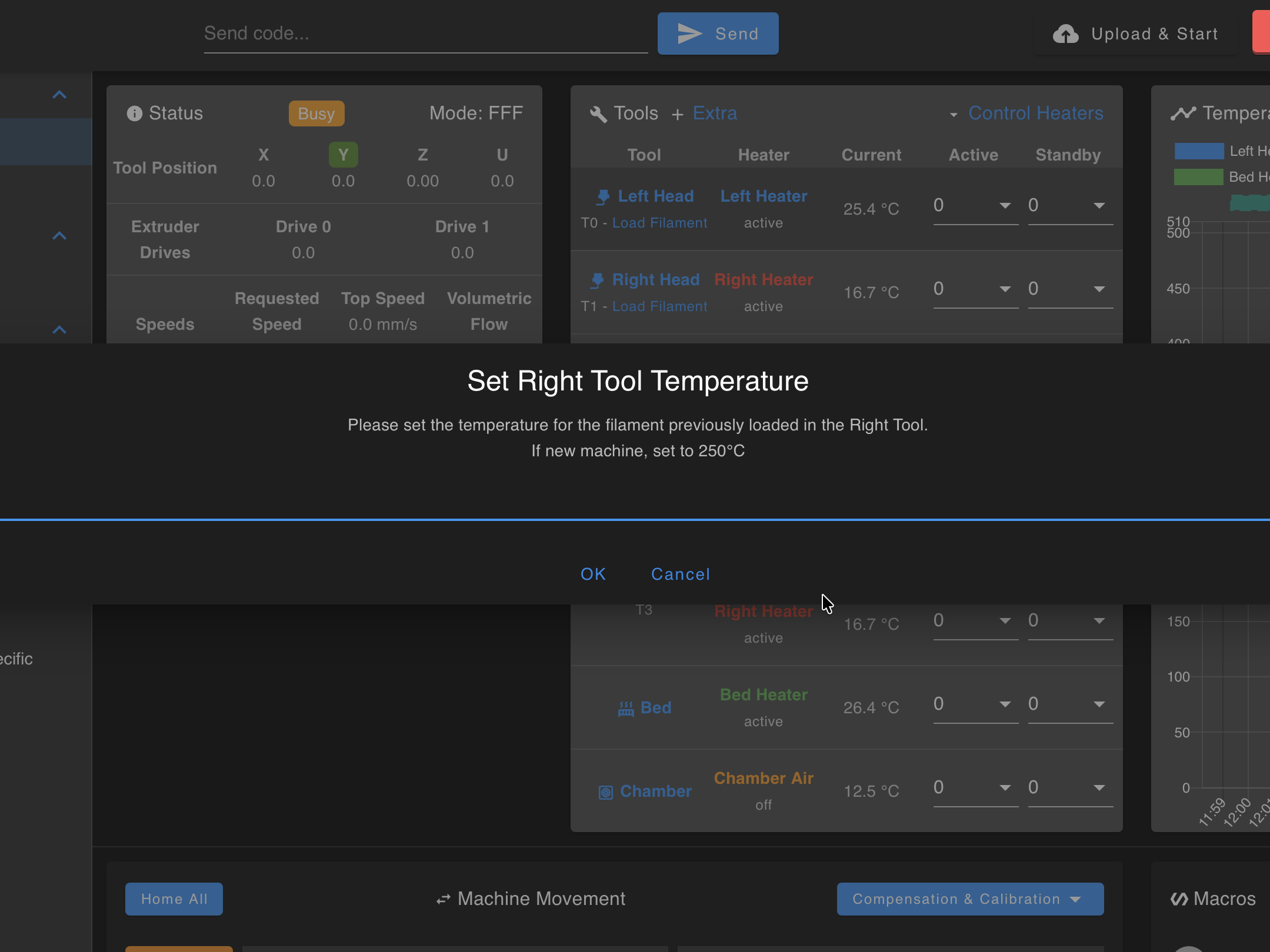
Enter the target temperature for the left tool (Tool 0) when prompted. Use the temperature matching the filament last loaded in that hotend. For a new machine or clean nozzles, use 250 °C.
-
Enter the target temperature for the right tool (Tool 1). Same rule – match the loaded filament, or use 250 °C if clean.
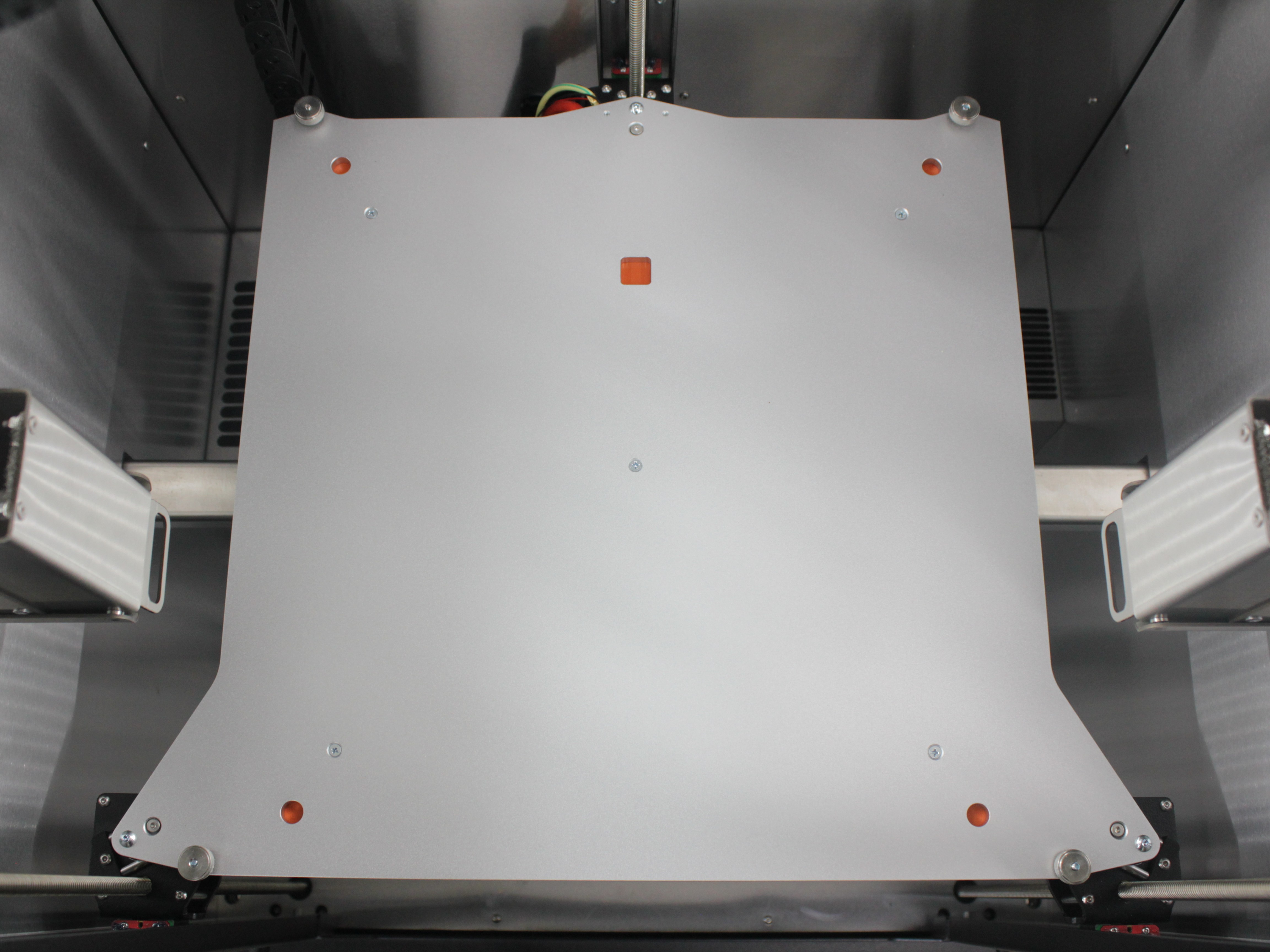
- Confirm that the build plate has been removed when prompted. Click OK.
- The printer will automatically heat both nozzles, home all axes, and prepare for calibration.
2. Nozzle Cleaning
Nozzles and hotends reach operating temperature
Do not touch the hotends, heater blocks, or nozzles without heat-resistant gloves.
- The printer runs an automated nozzle wipe using the built-in cleaning brushes. Wait for it to complete.
Keep the brush clear of heater and sensor wires
When cleaning nozzles with a wire brush, keep the brush away from heater cartridge and temperature sensor wires. A short circuit can blow a fuse or damage the mainboard.
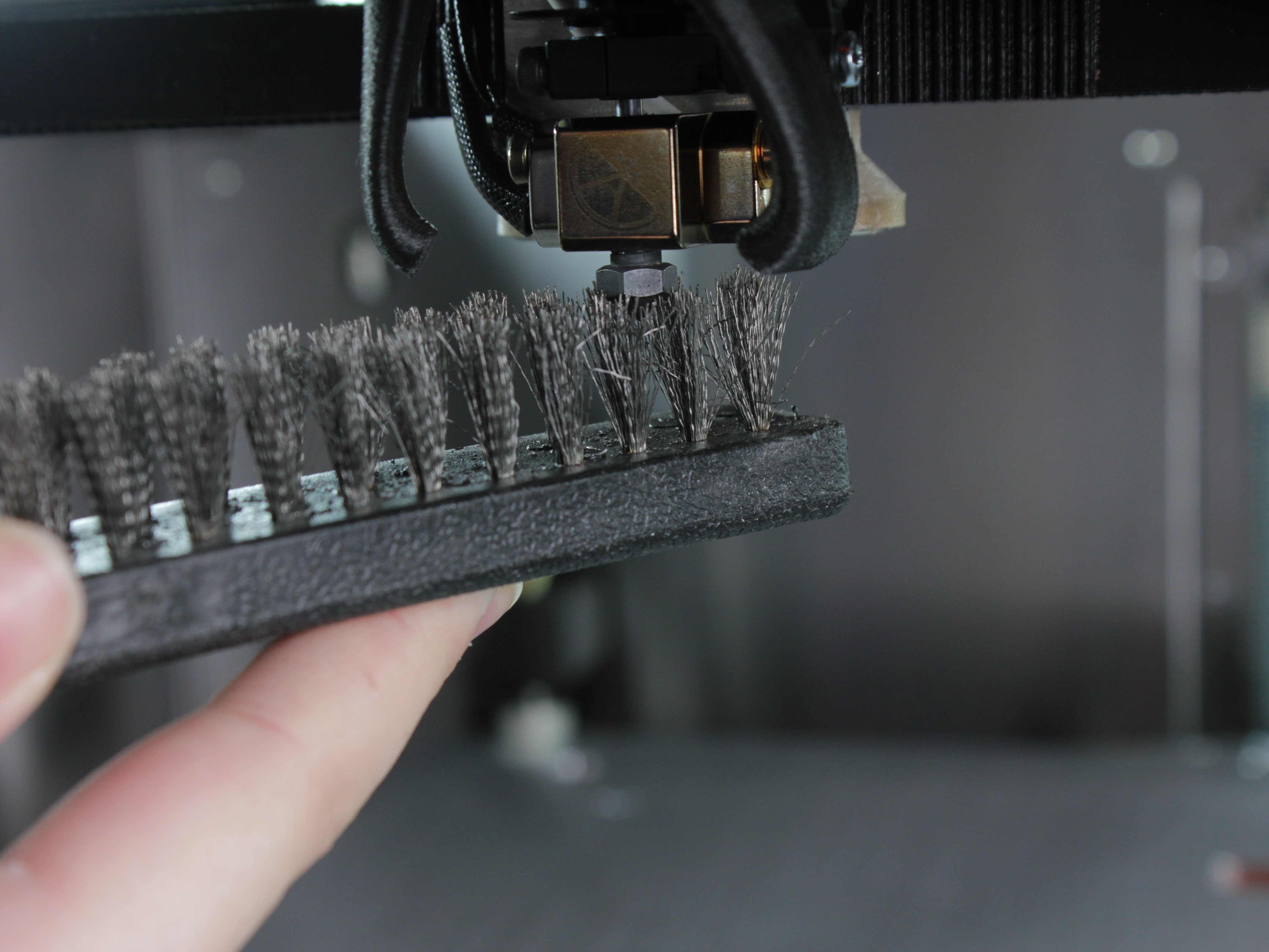
- When prompted, manually clean both nozzle tips with a wire brush (brass preferred). Remove all plastic residue – even small traces affect probe accuracy.
Heat Break Check
While the nozzles are accessible for cleaning, verify the position of the heat breaks on both tool heads:
Heat break position affects calibration accuracy
If the heat break body (the part that clamps inside the heat sink) protrudes from the heat sink, auto-calibration may fail or produce incorrect results. Stop calibration and adjust the heat break before continuing.
a) Check that neither heat break protrudes more than 1mm (≈ 1/32 in.) from the heat sink.
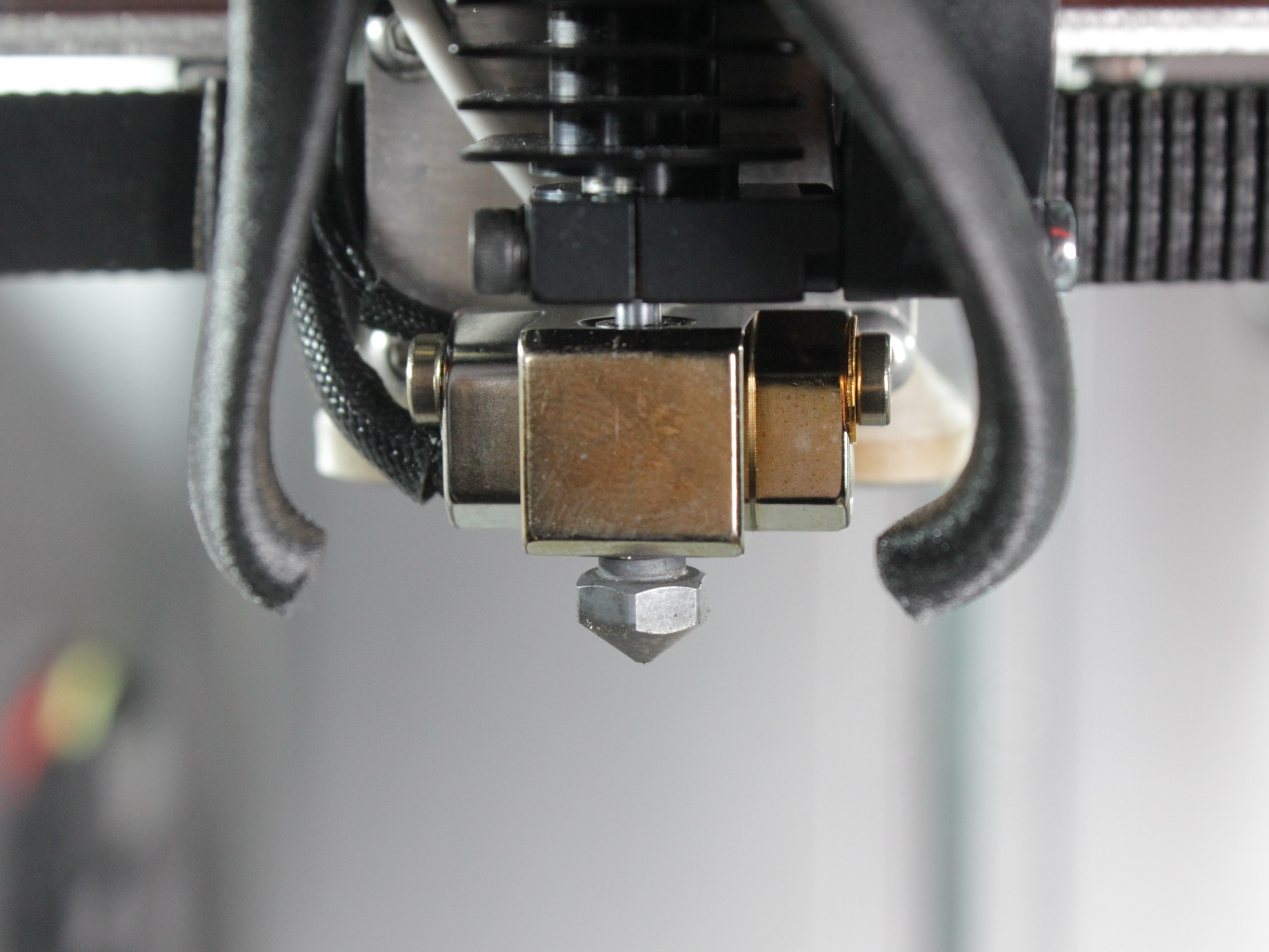
b) If a heat break protrudes too far, the body will be visibly extended from the heat sink:
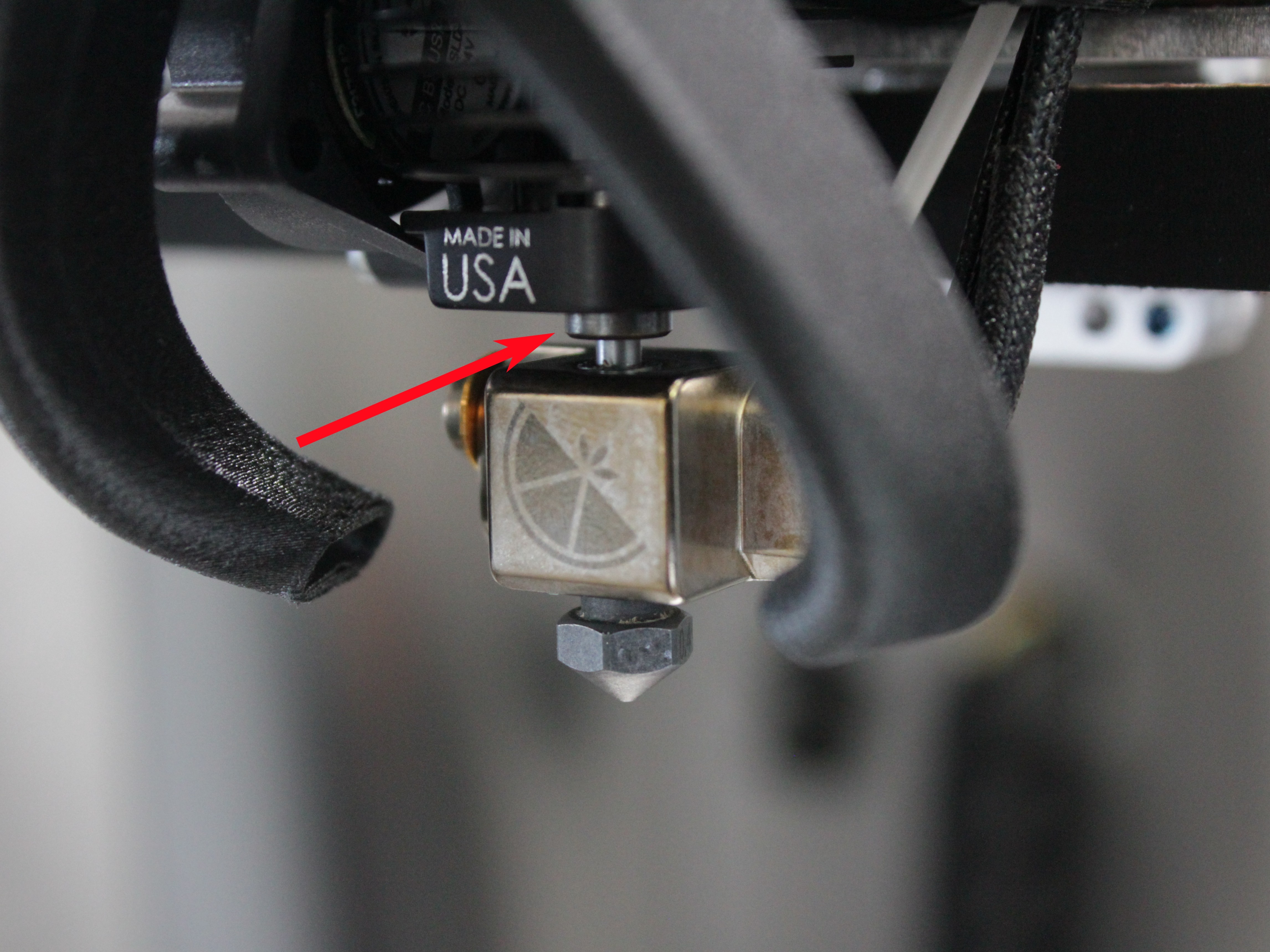
c) To correct this before starting calibration, locate the heat break set screw for that tool head - the black hex set screw on the heat sink, directly above the heater block (the one the red arrow points to in the photo at step 15). This is the only screw you loosen to move the heat break - do not loosen the silver or brass screws beside the heater block.
d) Use the two-screwdriver method: with a 2 mm hex screwdriver, loosen the set screw. Then use a second tool (e.g., the 2.5 mm hex wrench from the kit) to gently level the heater block and push the heat break upward until it protrudes no more than 1 mm. Retighten the set screw.
e) If you discover this issue during calibration, click Cancel, adjust both heat breaks as described above, then restart the Auto Calibration macro.
f) Complete this check for both tool heads before proceeding.
- Confirm Nozzles are Clean in the Web Interface prompt, then confirm Heat Breaks are All the Way Up on the next prompt.
Probe approach message is not a fault
During probing, the Web Interface may briefly show "Error: Probe was not triggered." That message is part of the normal approach sequence, not a real fault. The process approaches the bed in small steps; we're aware the wording isn't ideal.
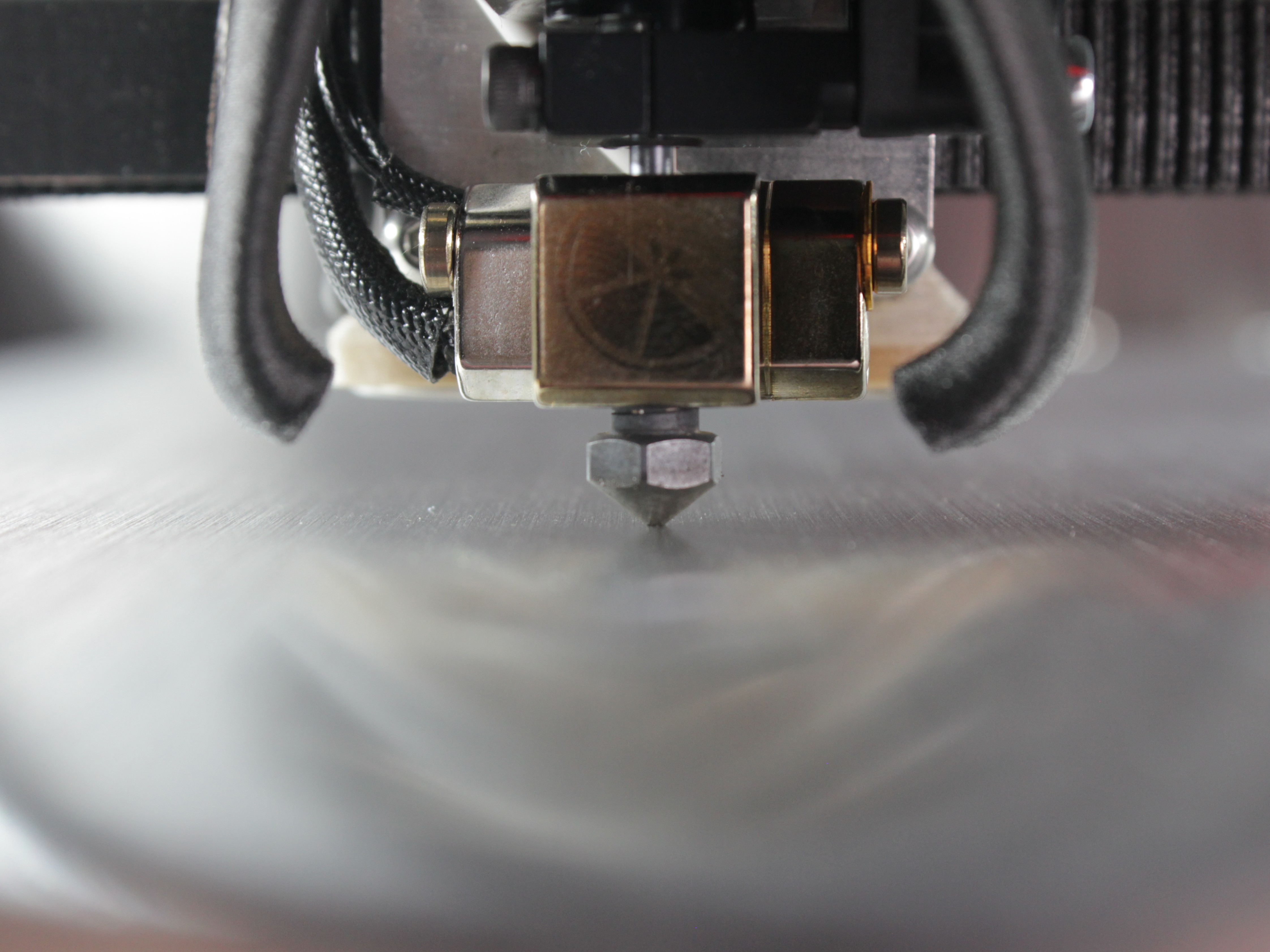
- The printer homes all axes again and begins probing.
3. Tool Height Calibration
- The machine probes both nozzles against the bed to measure their height difference. The target is a deviation under 50 microns (0.05 mm).
- If the deviation is within tolerance, the printer proceeds automatically to Z-Offset Calibration. Skip to Remaining Calibration Steps.
- If the deviation exceeds 50 microns, a prompt titled "Nozzles deviated by … mm" appears with three options: Calibrate, Skip, or Cancel. This adjustment is only needed for Mirror Mode and Duplicate Mode – if you do not use those modes, you can Skip it. Select Calibrate to adjust the heat break.
4. Adjusting the Heat Break (If Required)
Hotend parts stay hot during adjustment
The hotend components are hot. Wear heat-resistant gloves or use tools to avoid burns.
- The Web Interface prompt will indicate which tool (left or right) needs adjustment. Identify the corresponding nozzle.
- Locate the set screw on the side of the heat sink that secures the heat break for the indicated tool.
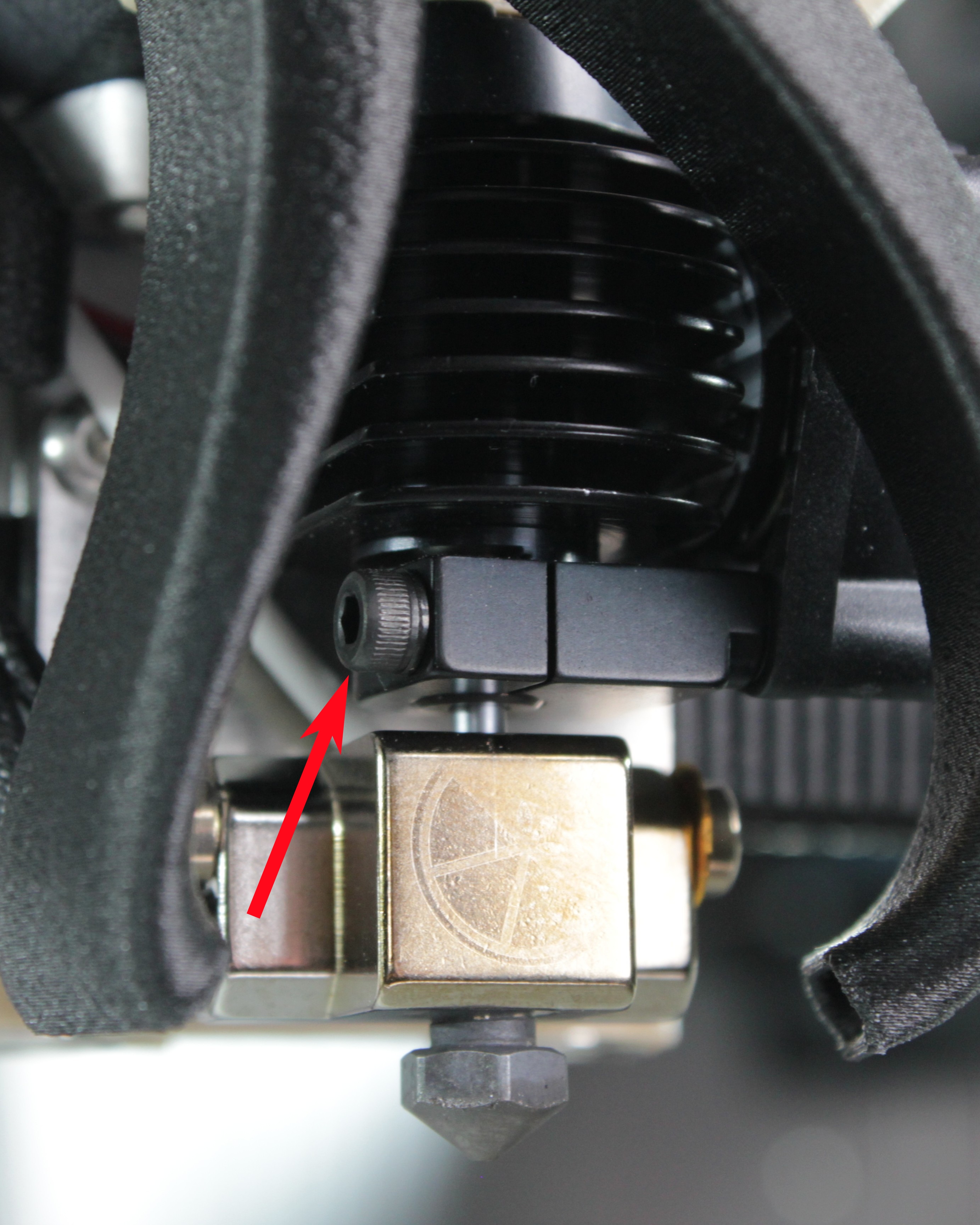
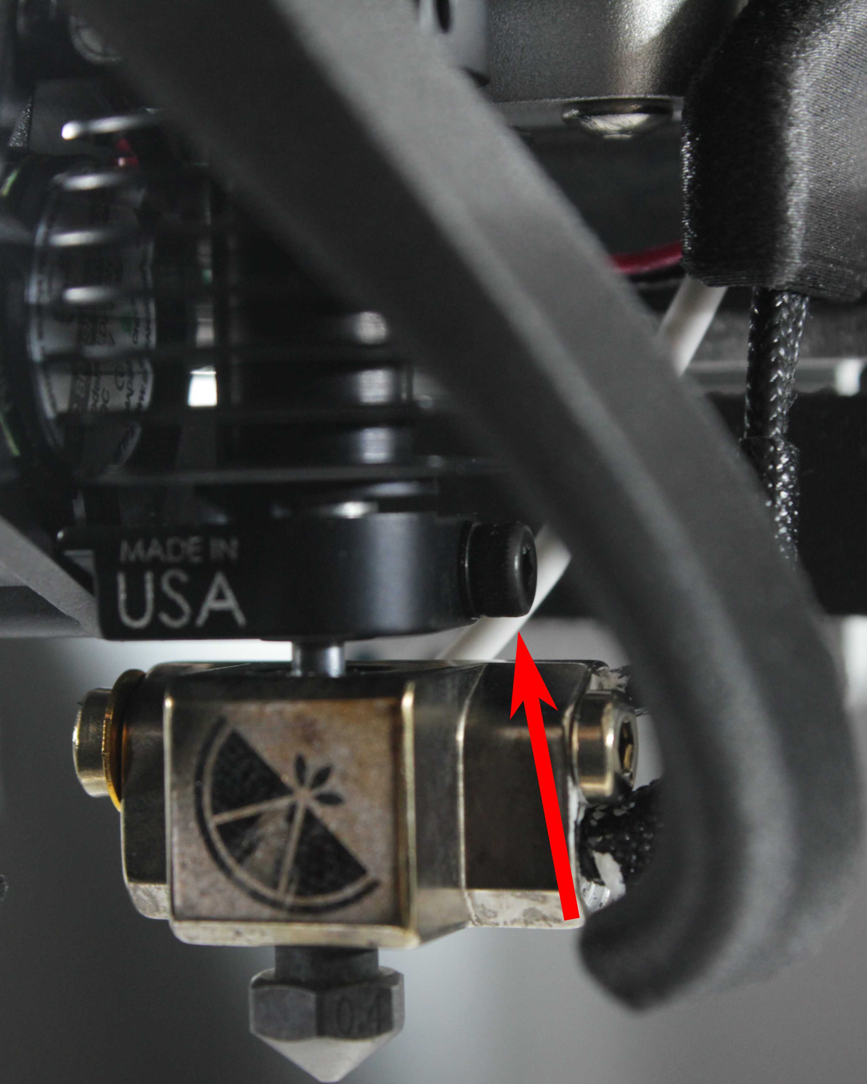
- Loosen the set screw with a 2 mm hex screwdriver – just enough that the heater block can slide up and down. Do not fully remove it.
- Use the two-screwdriver method: hold a second tool (e.g., the 2.5 mm hex wrench) against the heater block to level it and push it down approximately 2-3 mm.
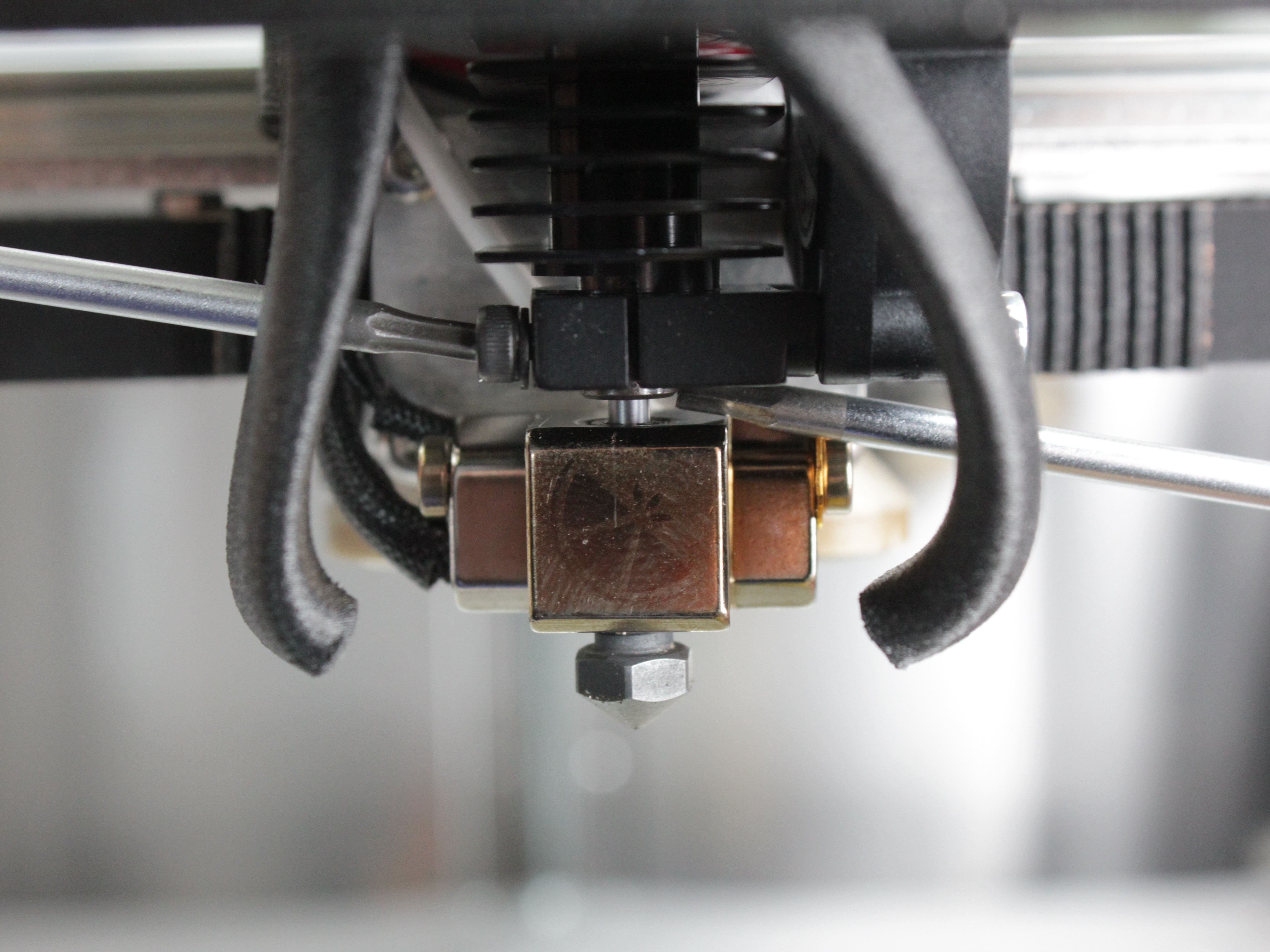
Use tools on the heater block – do not use bare fingers
The heater block is hot. Use tools – do not push with bare fingers.
- Slightly re-tighten the set screw – just enough to prevent the hotend from wobbling, but loose enough that the bed can still push it upward during the next probing sequence. Too tight = bed can't adjust; too loose = inaccurate result.
- Click OK in the Web Interface prompt. The printer probes the nozzle against the bed, pushing the loosened hotend upward until it matches the height of the other nozzle.
Tighten the Heat Break
- Once the printer finds the correct height, it positions the nozzle for access. Before tightening, check the hotend orientation:
Point the heater block straight toward the front
The heater block must face straight toward you (toward the front of the machine). If it is rotated at an angle, it can contact the fan shroud during printing and melt it.
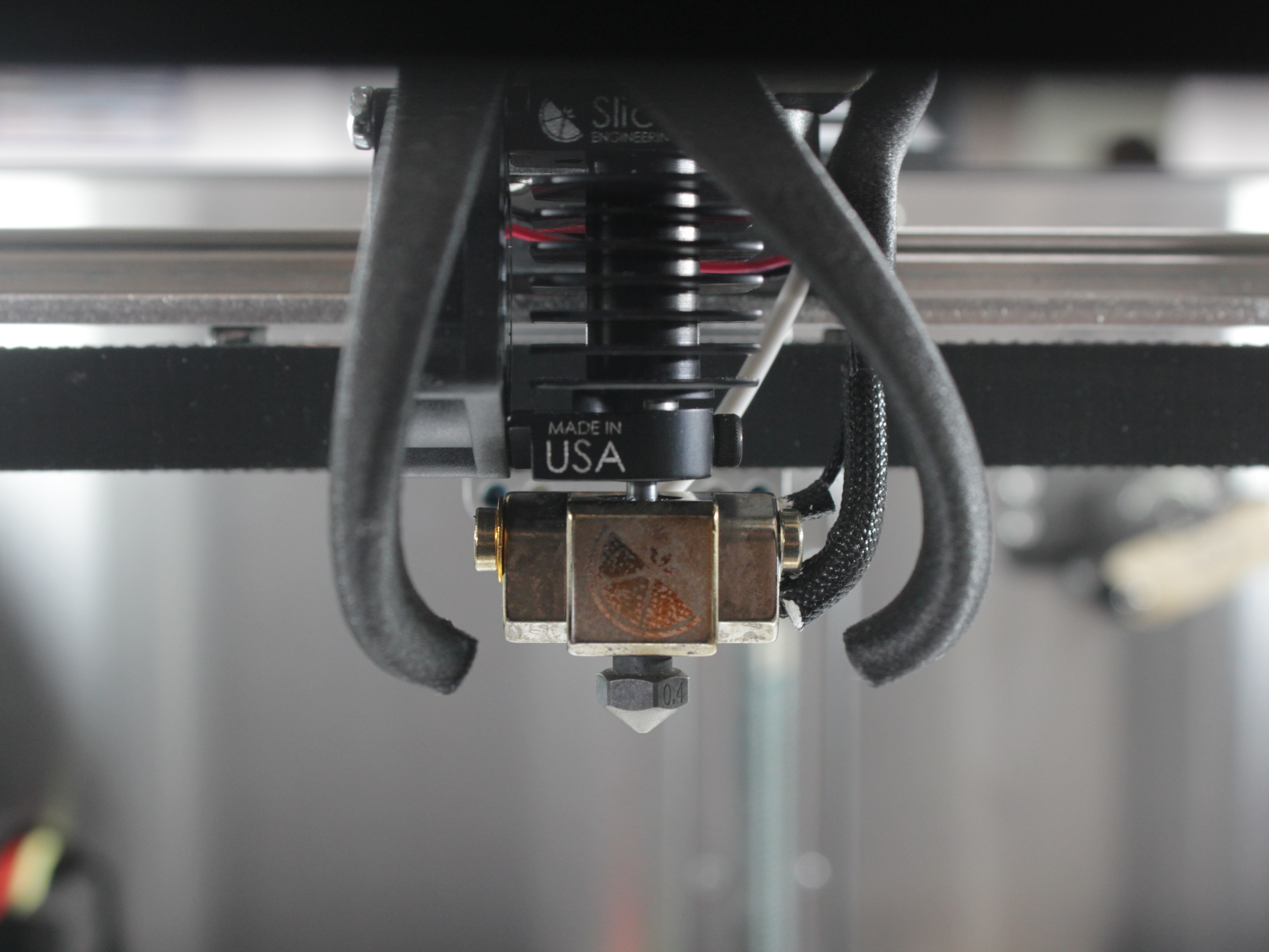
-
Use the two-screwdriver method to tighten: hold one 2.5 mm hex screwdriver against the heater block to keep it facing straight forward, and simultaneously tighten the heat break set screw with the 2 mm hex screwdriver. This prevents the heater block from rotating while you lock it in place.
-
Click OK to confirm. The machine re-runs the tool height check. If within tolerance, it proceeds automatically. If still out of tolerance, repeat steps 14–22.
5. Remaining Calibration Steps
- After tool height calibration passes, the following steps run automatically without user interaction:
- Z-Offset Calibration – sets the first-layer height
- Mesh Bed Calibration – creates a bed compensation map (runs only in Auto mesh-compensation mode; skipped in Manual, the default)
- XY Auto Squaring – corrects axis perpendicularity, and calculates steps per mm when that option is enabled (runs if either is enabled)
- XY Offset Calibration – measures the nozzle offset by probing a hole in the bare bed
- When all steps complete, the printer displays a summary with calibration results:
- Tool 1 Z Offset – the height difference between Tool 0 and Tool 1. The two nozzles can never be made perfectly level mechanically, but the printer compensates for this offset automatically. This is critical for dual-head printing (Multi color/Dual Material Printing) – it ensures consistent layer height and maximum bonding strength between two materials.
- Z-Offset – the distance between the nozzle tip and the bed surface, determines how well the first layer adheres to the build plate.
- Tool 1 Y-Offset – the Y-axis positional offset between the two nozzles. Used to align toolheads in the XY plane so that multi-color and multi-material prints line up correctly.
- Tool 1 U-Offset – the U-axis (secondary X) positional offset between the two nozzles. Same purpose as Y-Offset but in the X direction.
- XY Skew – the perpendicularity correction between X and Y axes. Compensates for any mechanical skew in the crossbar.
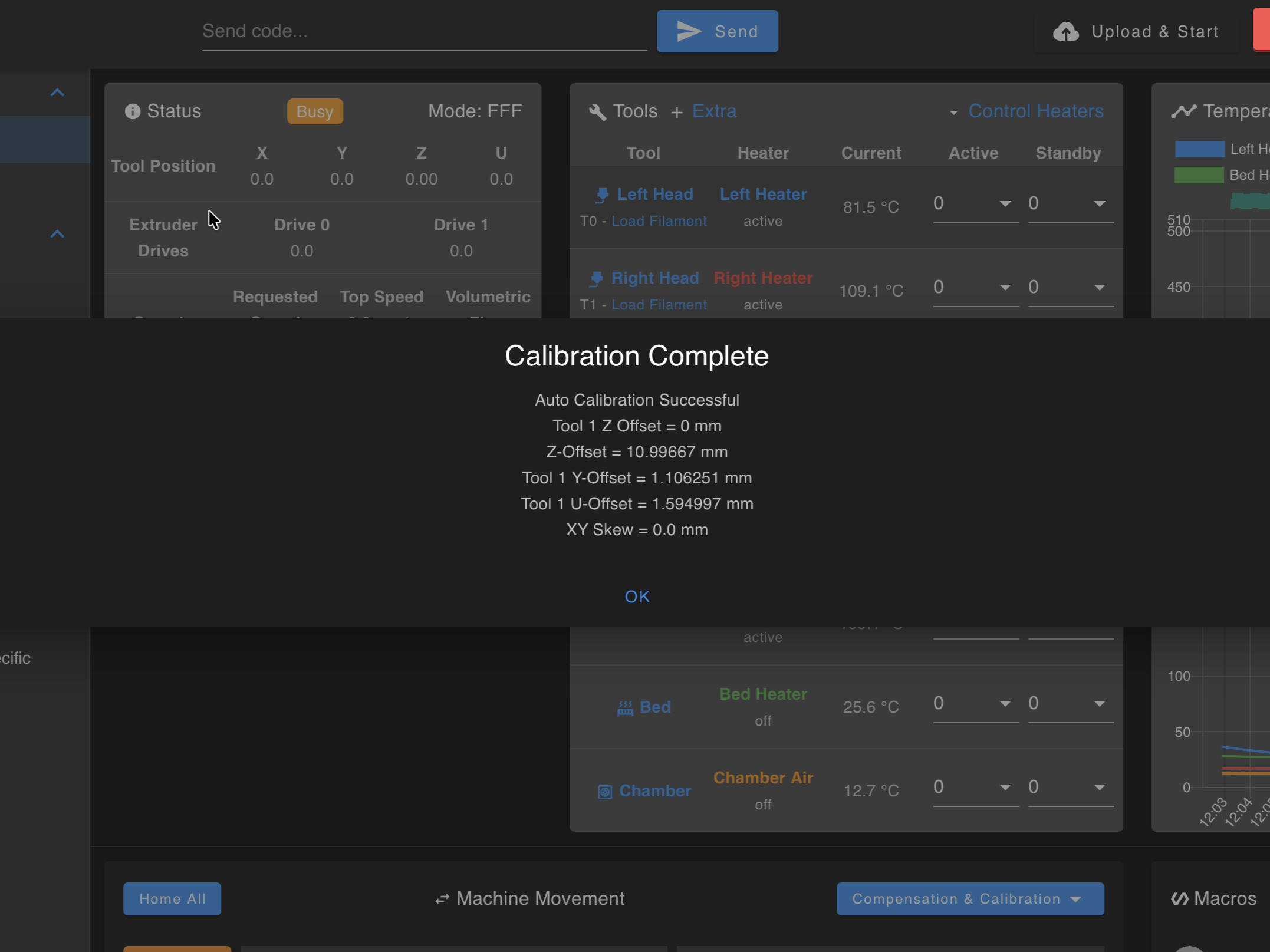
- Click OK to dismiss the results. Reinstall the build plate – the printer is ready for use.
After Calibration: Verify XY Alignment
Auto-calibration measures the XY offset between Tool 0 and Tool 1, but that result should be verified with a manual XY test print before you rely on it for dual-head work. The automated probe can miss small offset errors that only show up in an actual print.
Run a manual XY verification after auto-calibration
If you print with both toolheads at the same time – that means Mirror Mode, Duplicate Mode, or any multi-color / multi-material print – mechanically verify the XY alignment after auto-calibration. Follow the XY Alignment Calibration procedure to confirm and fine-tune the offset with a test print.
What these dual-head modes mean (so you know whether this applies to you):
- Mirror Mode – both toolheads run simultaneously, and Tool 1 prints a mirrored (symmetrical) copy of what Tool 0 prints. Used to make a left/right pair in a single print.
- Duplicate Mode – both toolheads run simultaneously and print two identical copies of the same part, doubling your output.
- Multi-color / multi-material – the two toolheads print different colors or materials into the same part, so their positions must line up exactly.
For full setup of these modes, see the Mirror & Duplicate Mode guide.
Printing with a single toolhead?
If you only ever print with one toolhead at a time – no Mirror Mode, no Duplicate Mode, no multi-color or multi-material prints – the nozzle-to-nozzle XY alignment does not affect your results. You can skip the manual XY verification.
FAQ
Troubleshooting
Support
If you could not find an answer here, reach out to our support team.