XY Alignment
Align T0 and T1 toolheads on the 22 IDEX V4 with the cylinder or linear gauge test, then correct color shifts and gaps using live XY offset macros.
XY Alignment ensures both toolheads (T0 and T1) print at the same position for multi-material and multi-color parts. Auto Calibration measures the offset by probing each nozzle into the build plate cutout, but dirty nozzles or bent heat breaks cause incorrect offsets. Verify and fine-tune alignment with a test print and live adjustment macros after Auto Calibration, toolhead service, or when you see color shifts or gaps in dual-extruder prints.
Two methods:
- Cylinder Test - contrasting-color filaments; clearest visual feedback.
- Linear Alignment Test - a printed measuring gauge you read like a caliper; precise to 0.1 mm and works with any colors.
Before you begin - safety and risk
Read the Safety - Before You Begin article to understand the hazards involved in working on the Vision Miner 22IDEX V4 - including electrical, thermal, mechanical, and chemical risks. All procedures in this wiki are provided as recommendations only. By choosing to follow any procedure, you do so at your own risk.
Bent heat breaks invalidate calibration
Both nozzles must point straight down. Inspect each hotend from the side - if a heat break is bent in any direction, calibration results will be incorrect. Replace bent heat breaks before calibrating.
Run Auto Calibration before XY alignment
Run Auto Calibration before XY alignment.
YouTube media is off. Allow it in cookie settings to load this video.
Watch on YouTubeTools and Materials
- Vision Miner 22IDEX V4 with 0.4 mm nozzles on both toolheads.
- Two filaments loaded (contrasting colors recommended for cylinder test).
- Web Interface access.
Test files:
| Method | File | Source |
|---|---|---|
| Cylinder Test | XY - Alignment Test.gcode | Jobs > Test Prints on the printer, or download |
| Linear Alignment Test | XY_aligment_linear_ABS.gcode | download |
T1 moves relative to T0
The left toolhead is T0, the right toolhead is T1. T0 stays fixed - every adjustment moves only the right toolhead (T1). The direction words (Left / Right / Forward / Backward) are from your point of view standing in front of the machine. Rule of thumb: move T1 toward the side that shows too little of its color.
The arrow in each macro name (for example ← Move T1 Left) is part of the on-screen button label - match it exactly to the button you click in the Web Interface.
Cylinder Test (contrasting filaments)
Use when you have contrasting filament colors (black + white, black + yellow). Color contrast makes misalignment easy to spot.
- Load contrasting filaments into both toolheads. Verify both extrude cleanly.
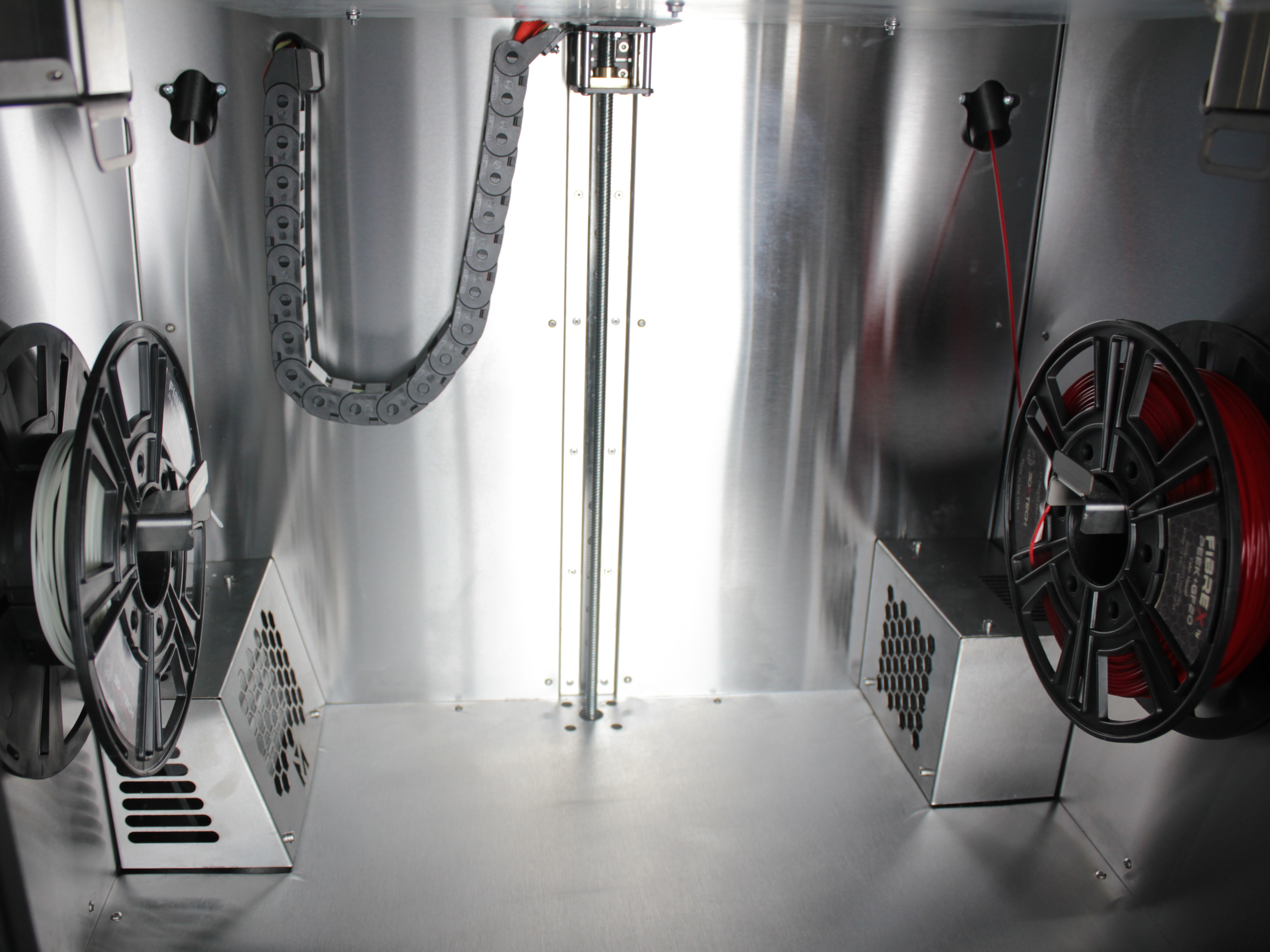
- Start XY Alignment Test.gcode (from Jobs > Test Prints or the download link above). When prompted, set temperature and filament settings.
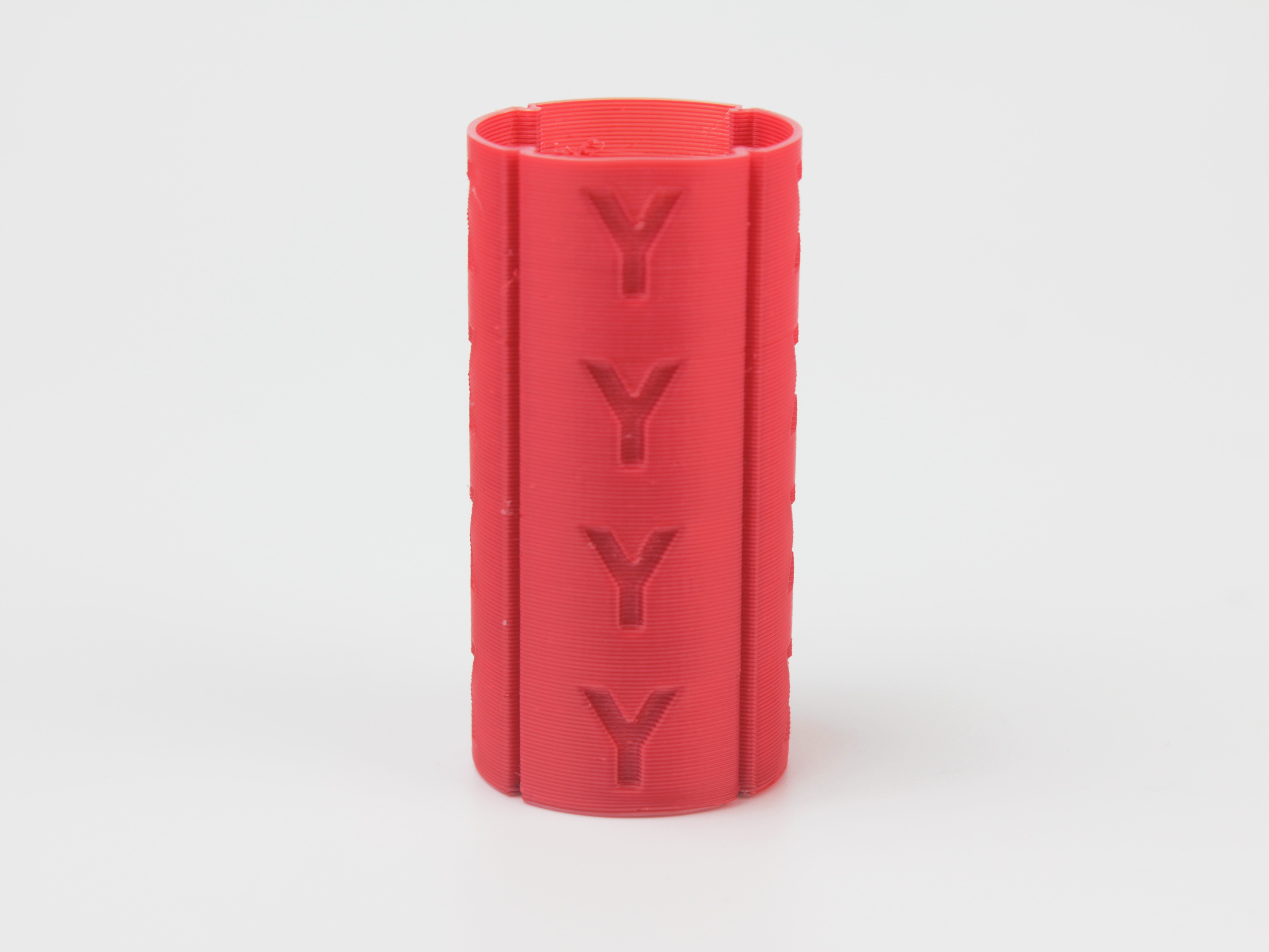
- Let it print 5-10 layers. The test produces a vertical cylinder alternating T0 and T1 each layer.
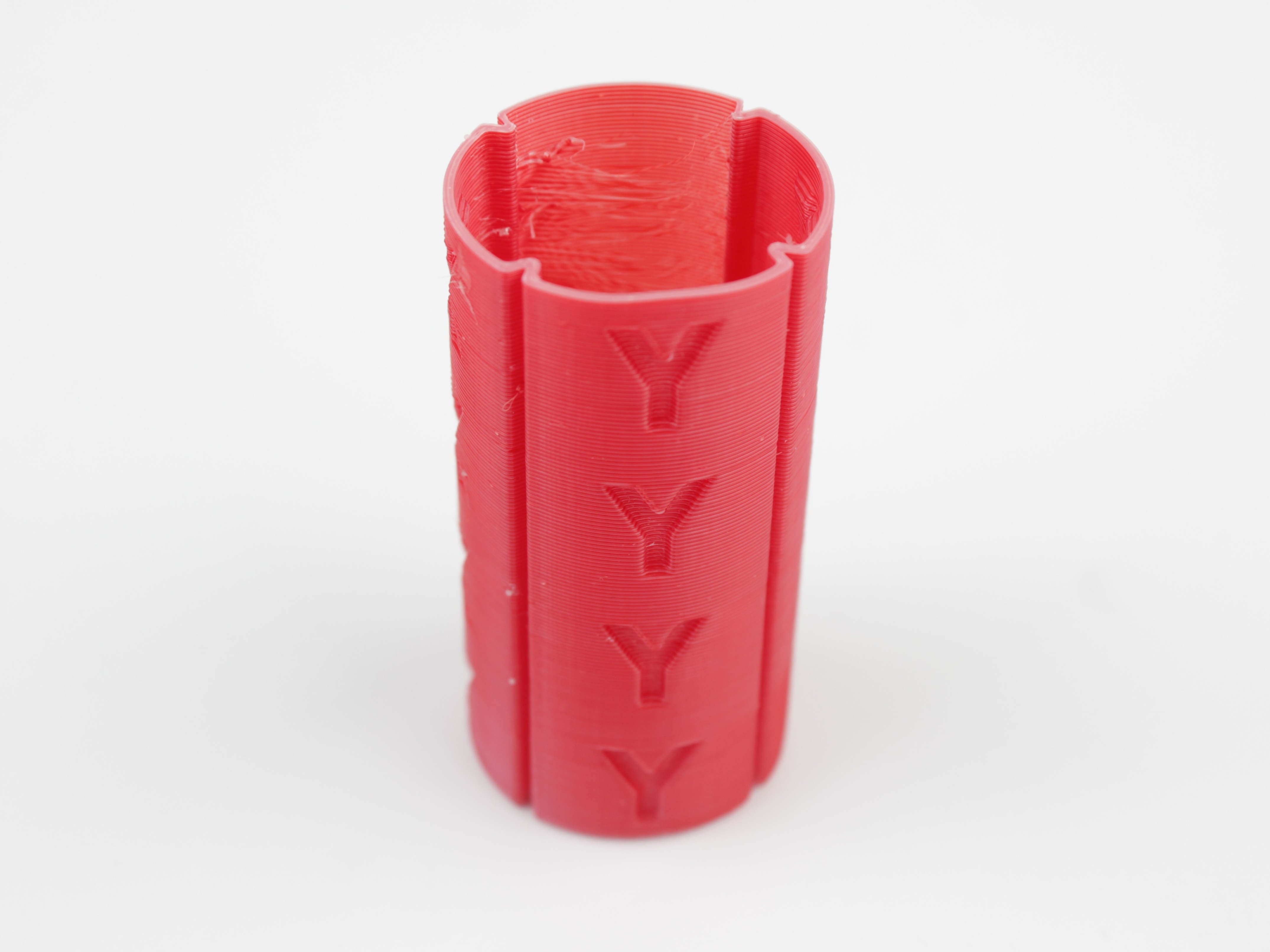
- Observe the cylinder from all sides - front, back, left, right. A well-aligned print shows equal color distribution from every angle.
A misaligned print shows one color dominating on one side:
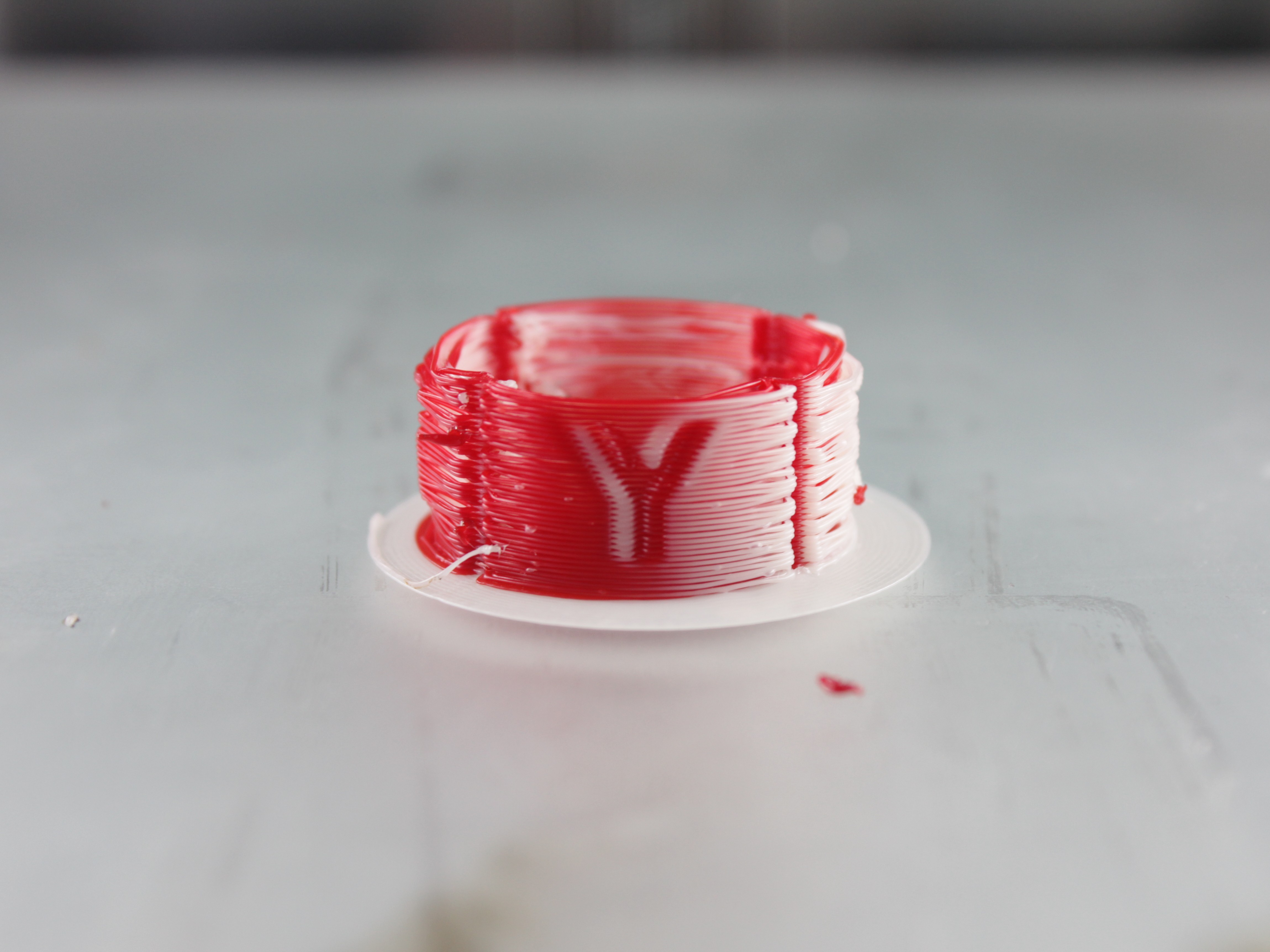
Worked example - reading a misaligned cylinder
First decide which toolhead is your base: its filament is the reference and you do not move it. On this machine that is T0 (left), and you adjust T1 (right) relative to it.
Say T0 (left) has red filament and T1 (right) has white. Looking at the cylinder, the white (T1) color is pushed over to the right side - so T1 is shifted right and needs to move back left. From the table below that is ← Move T1 Left. In this example the colors line up evenly front-to-back, so there is no Y shift to correct.
- If color distribution is uneven, open the Web Interface > Macros > System > Calibration > Live XY Offset Adjustment.
- Identify which side shows more of one color and click the corresponding macro. Each click moves T1 by 0.05 mm:
| Symptom | Macro |
|---|---|
| More color on the right | ← Move T1 Left |
| More color on the left | → Move T1 Right |
| More color on the front | ↓ Move T1 Backward |
| More color on the back | ↑ Move T1 Forward |
- Adjust live while the print runs. Make 1-2 clicks at a time, wait 5-10 layers to see the effect, then adjust again.
- Repeat steps 6-7 until the cylinder shows uniform color from all angles.
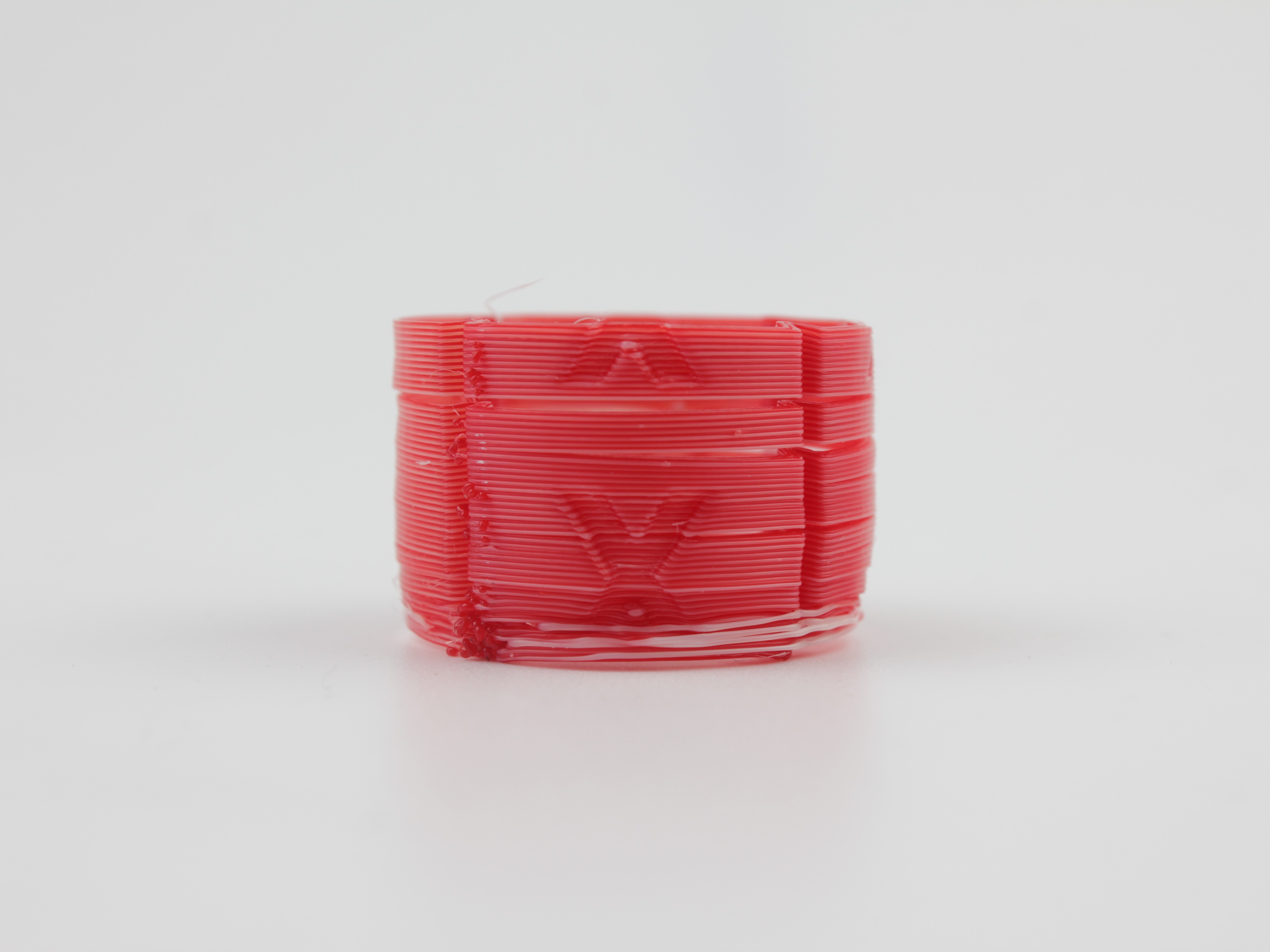
- Let the print finish. Remove and rotate to confirm even color from all angles.
Offsets save automatically
All offset values are saved automatically. No manual save or confirmation needed.
Linear Alignment Test (precise, any colors)
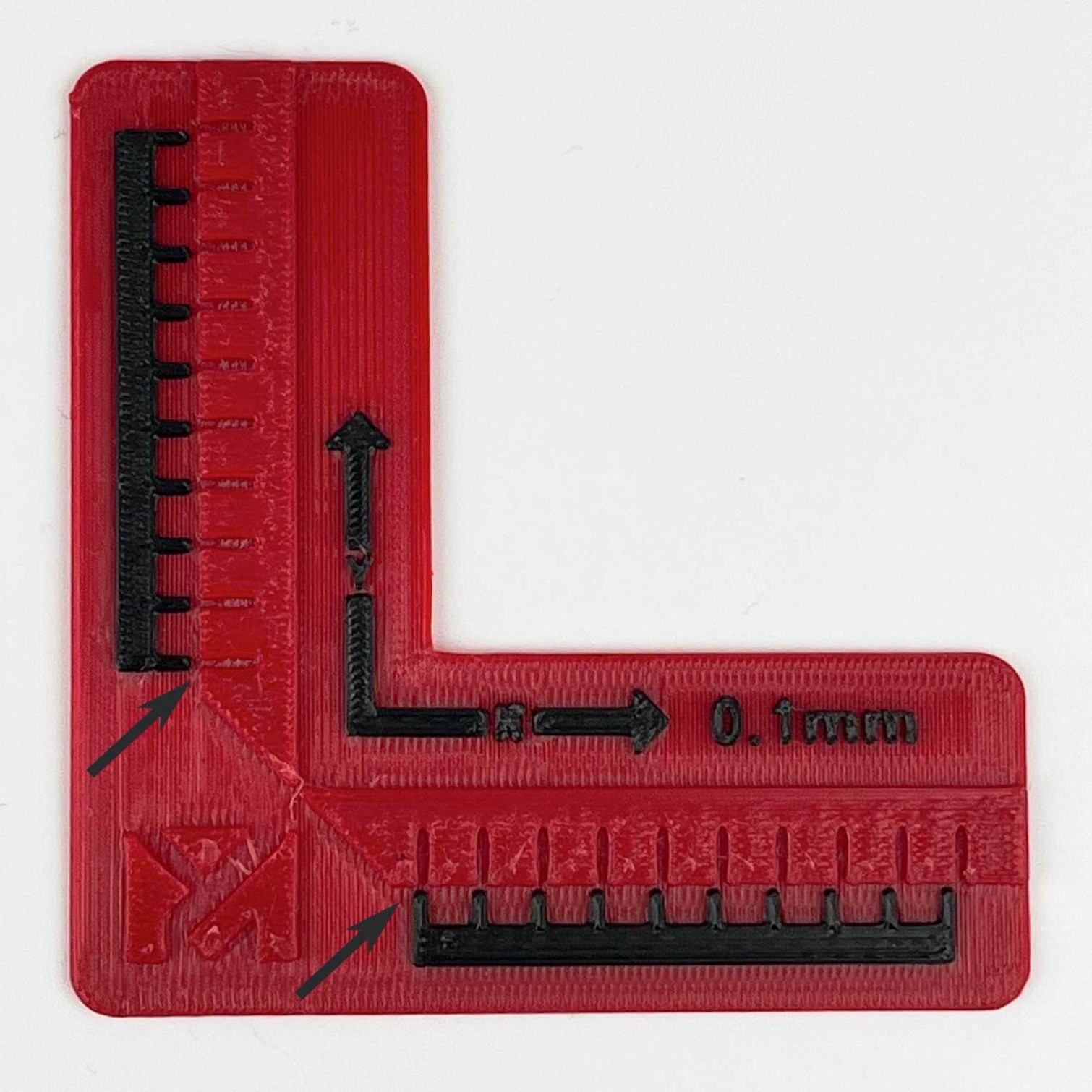
This method prints a small L-shaped measuring gauge that you read like a caliper. The red body is printed by T0 (the reference tool); the black scales are printed by T1 (the tool you align). It resolves offsets down to 0.1 mm and works regardless of filament color - use it when the cylinder test would not give clear feedback (similar colors or non-bonding materials), or whenever you want an exact numeric offset.
- Load filament into both toolheads, then download the Linear Alignment Test G-code and send it to the printer. It is a ready-to-print
.gcodefile, so no slicing is needed - just start the print from the printer. - Remove the print and set it in front of you. Each arm is a scale: the vertical arm is the Y axis, the horizontal arm is the X axis. On each arm an arrow marks the + direction, and one graduation equals 0.1 mm. The logo in the corner is the zero point.
-
Read one axis at a time, starting at the graduation nearest the logo:
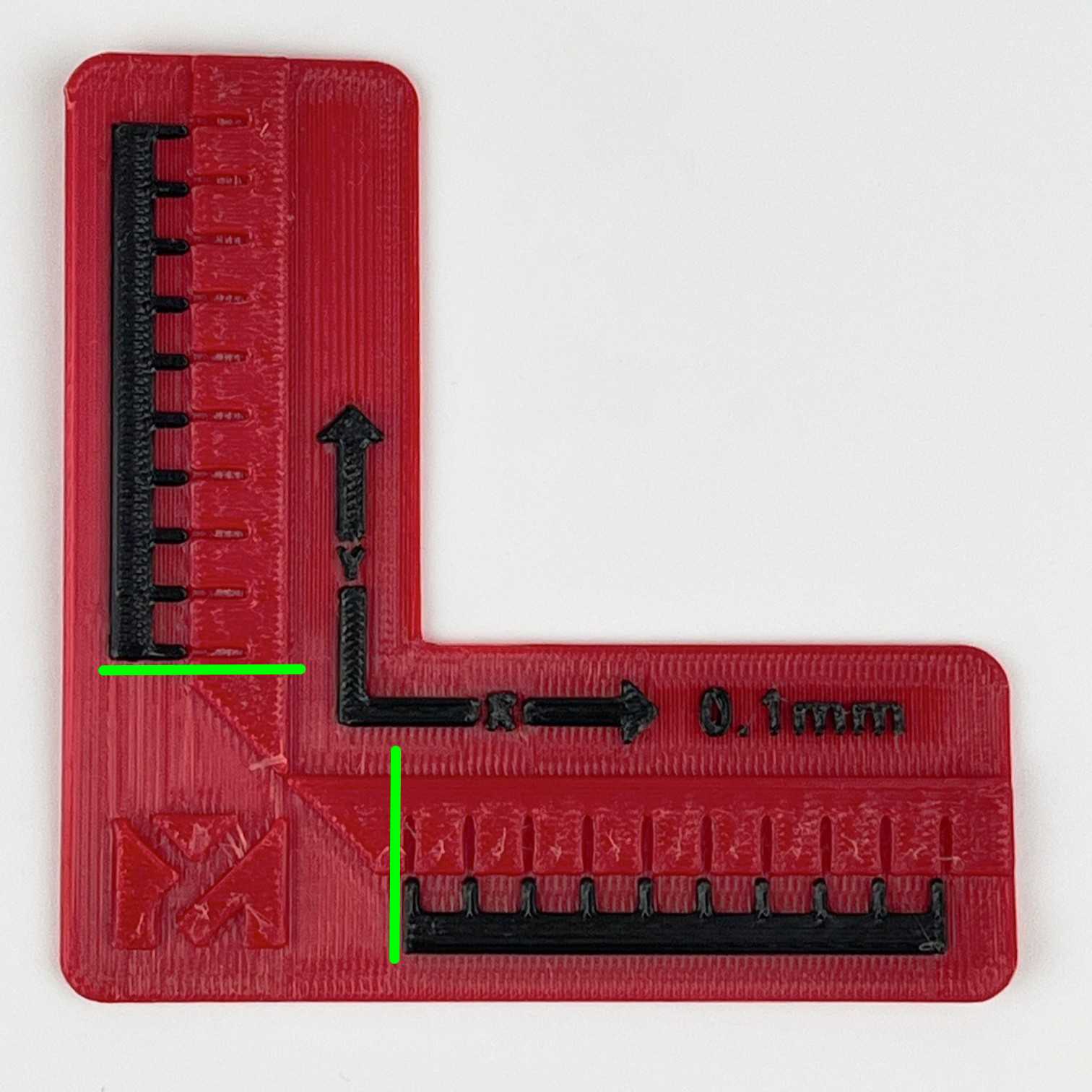
- Perfectly aligned: the black tooth sits exactly opposite (centered on) the red graduation.
- Otherwise, find the graduation that lines up exactly opposite a recess, and count how many graduations it is from the logo. Each graduation = 0.1 mm of offset.
-
Convert the reading to clicks. Each Live XY Offset macro click moves T1 by 0.05 mm, so 0.1 mm = 2 clicks:
- aligned at the first graduation → 0.1 mm → 2 clicks
- one graduation further → 0.2 mm → 4 clicks (N graduations → N × 2 clicks).
-
Pick the direction. The arrow on each arm is the + direction. If the black scale has shifted past the graduation toward the logo (overshoot), press +; if it falls short, press −:
Axis + (overshoot toward the logo) − (falls short) X (horizontal arm) → Move T1 Right ← Move T1 Left Y (vertical arm) ↓ Move T1 Backward ↑ Move T1 Forward -
Open Web Interface > Macros > System > Calibration > Live XY Offset Adjustment and click the chosen macro the calculated number of times. Offsets save automatically - no manual save needed.
-
Reprint and verify. Print it again and confirm the black scale now lines up with the red graduations on both arms.
Troubleshooting
FAQ
Support
If you could not find an answer here, reach out to our support team.