Bed Leveling Calibration
Level the 22 IDEX V4 bed left to right when the first layer prints too high on one side — the 3-square test print and the RHS Up and RHS Down macros.
This guide shows how to correct left-to-right bed leveling issues using the mesh compensation system. If parts on one side of the bed print too close or too far from the nozzle compared to the other side, the mesh compensation needs adjustment.
Before you begin - safety and risk
Read the Safety - Before You Begin article to understand the hazards involved in working on the Vision Miner 22IDEX V4 – including electrical, thermal, mechanical, and chemical risks. All procedures in this wiki are provided as recommendations only. By choosing to follow any procedure, you do so at your own risk.
Use this guide if, when printing – especially large parts or parts positioned toward the left or right sides of the bed – the first layer looks good in the center (where the printer is calibrated) but becomes too high or too low as you move toward the sides.
Vision Miner 22IDEX V4 machines ship in Manual mesh compensation mode with a starting value of 0. We recommend keeping Manual mode – you tune the left-to-right compensation once and it stays with the printer. If you experience first-layer inconsistencies left to right, follow the manual adjustment steps below.
We recommend printing with a Raft
The two print heads can never sit perfectly level with each other. We calibrate the primary head first, then use the secondary head to compensate for the remaining difference. Because that difference can never be dialed out completely, we recommend printing with a Raft – it gives you a reliable first layer and good adhesion across the whole bed.
Update to the latest firmware
We significantly improved this calibration procedure in firmware 4.1.x. If you are on an older version, we recommend updating first – see Firmware Update.
YouTube media is off. Allow it in cookie settings to load this video.
Watch on YouTubeHow it works
The printer supports two mesh compensation modes, and it stores a separate value for each – switching modes only changes which value is applied, it never erases the other:
- Manual Mode (default) – you adjust the left-to-right compensation yourself with the RHS Up / RHS Down macros while observing a test print. This is how machines ship from the factory.
- Auto Mode – the printer measures the bed during Auto Calibration with the Z-probe and applies that measured value automatically.
Your manual value is never overwritten. In Manual Mode (the default), Auto Calibration skips mesh probing entirely, so it leaves your manual value alone. The printer measures and stores a separate Auto value only when it is already in Auto Mode. Using RHS Up / RHS Down automatically switches the printer back to Manual Mode.
To switch between modes, go to Macros > System > Calibration > Mesh Calibration > Toggle Mode – it flips between Manual and Auto. See the Macros reference for details.
1. Testing Procedure
Use the 3-square test print to verify and tune bed leveling.
Get the test file
In the Web Interface, go to Jobs and navigate to Slicer > Tests. The Mesh Bed Test.gcode file is installed there by default and is already sliced – ready to print.
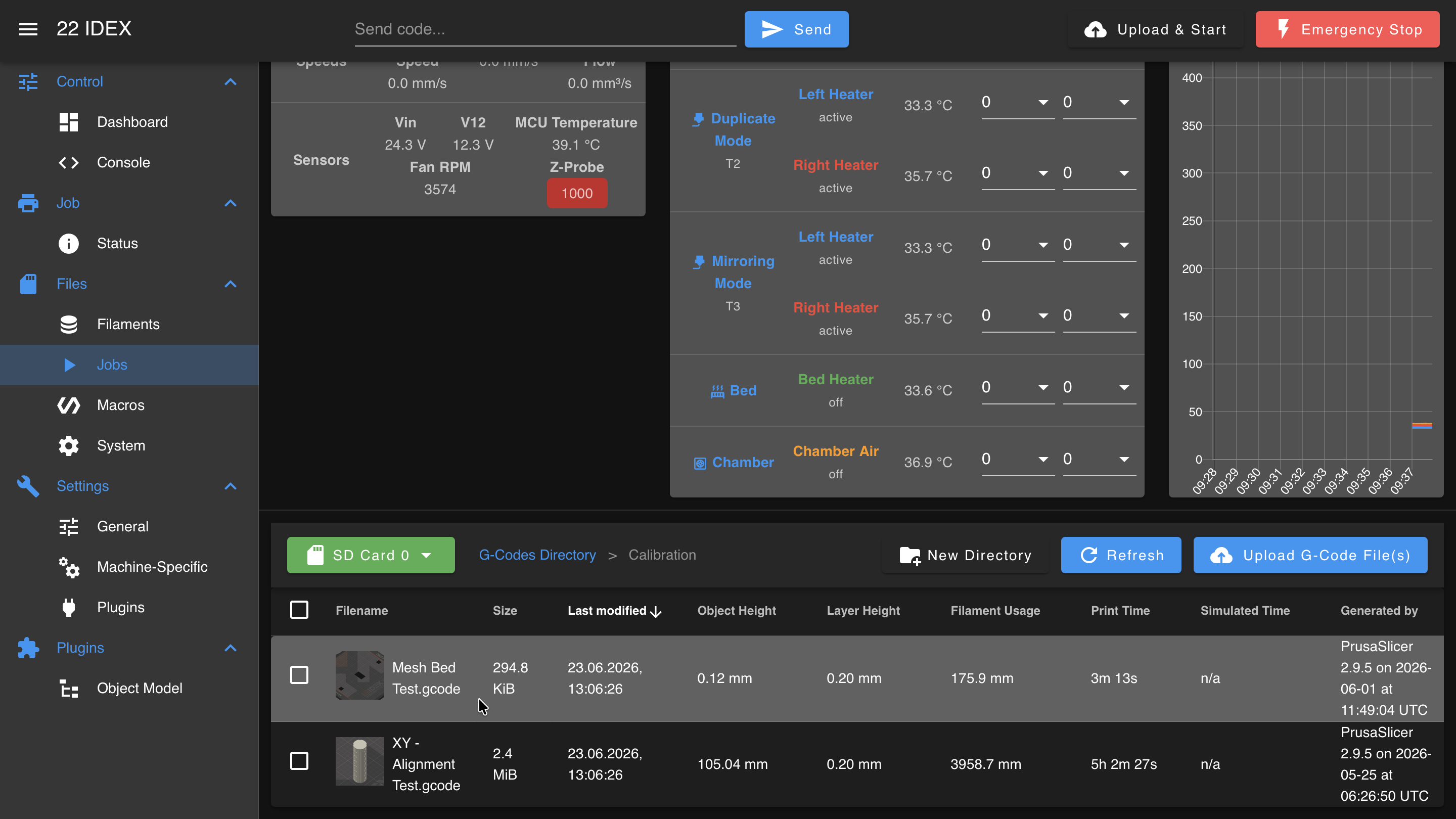
If it is not there, download it directly – Mesh Bed Test.gcode – then upload it to the Web Interface. In the Jobs tab, click Upload G-Code File(s):
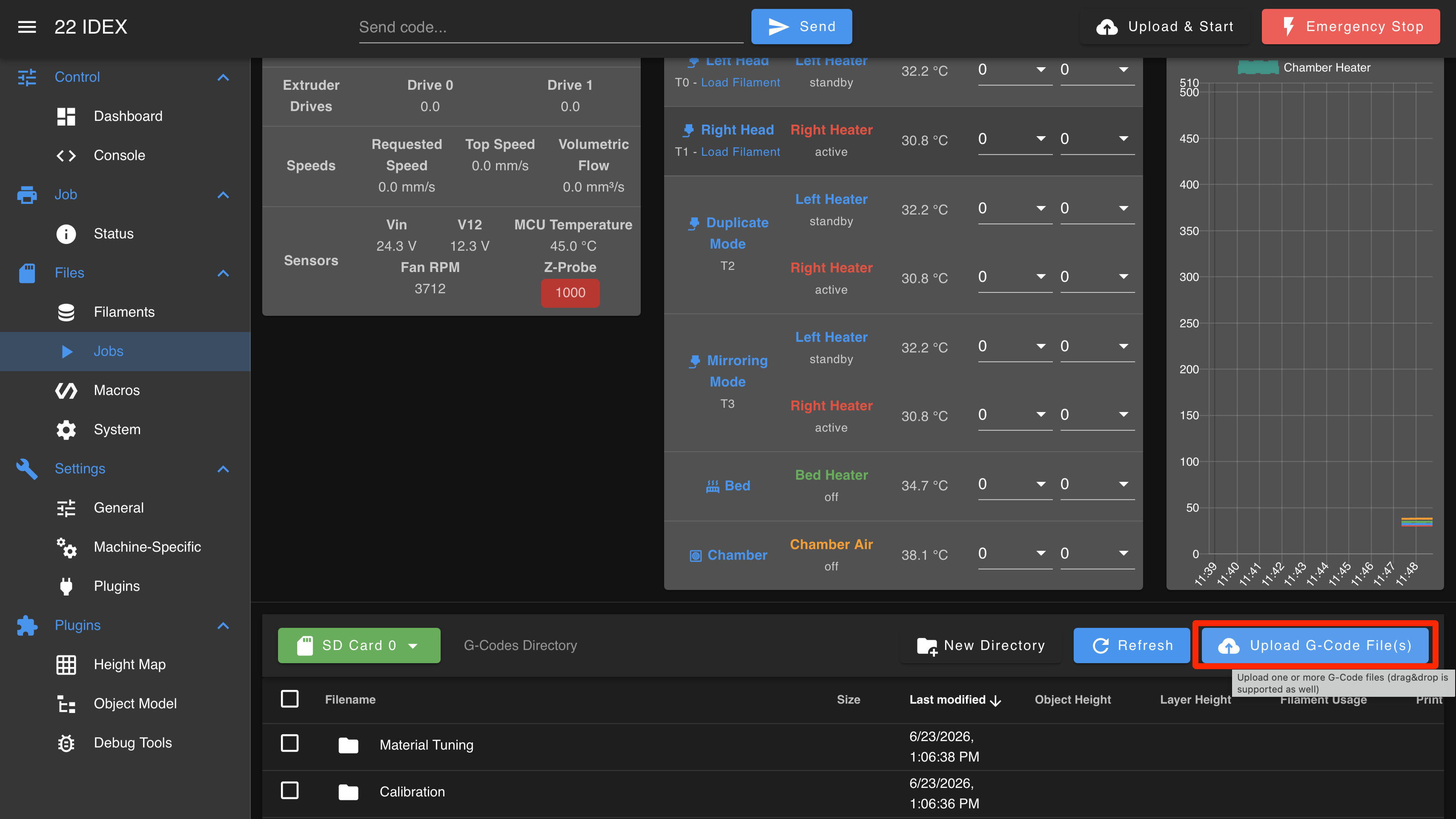
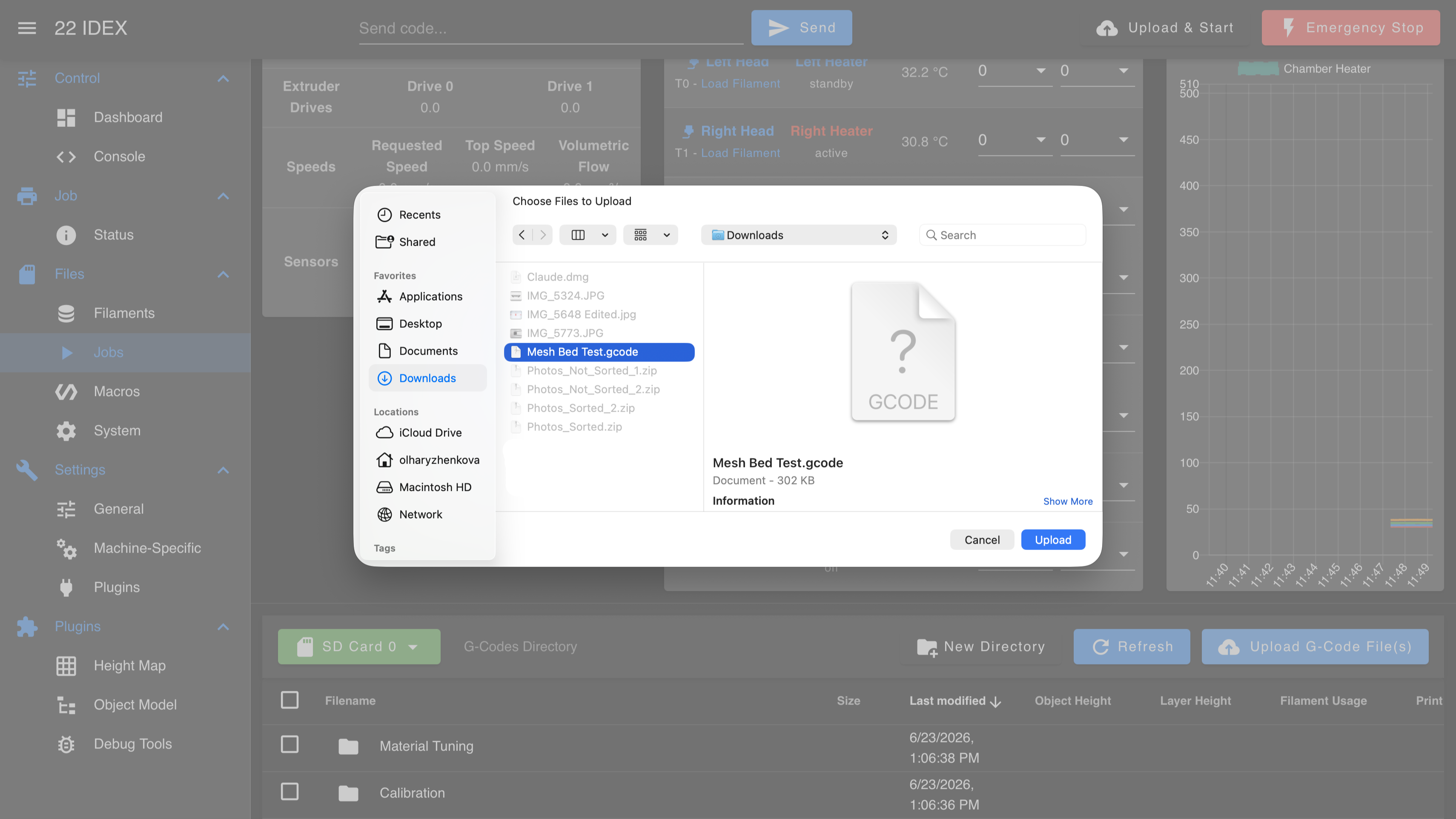
Select the downloaded Mesh Bed Test file and click Upload:
Print the test
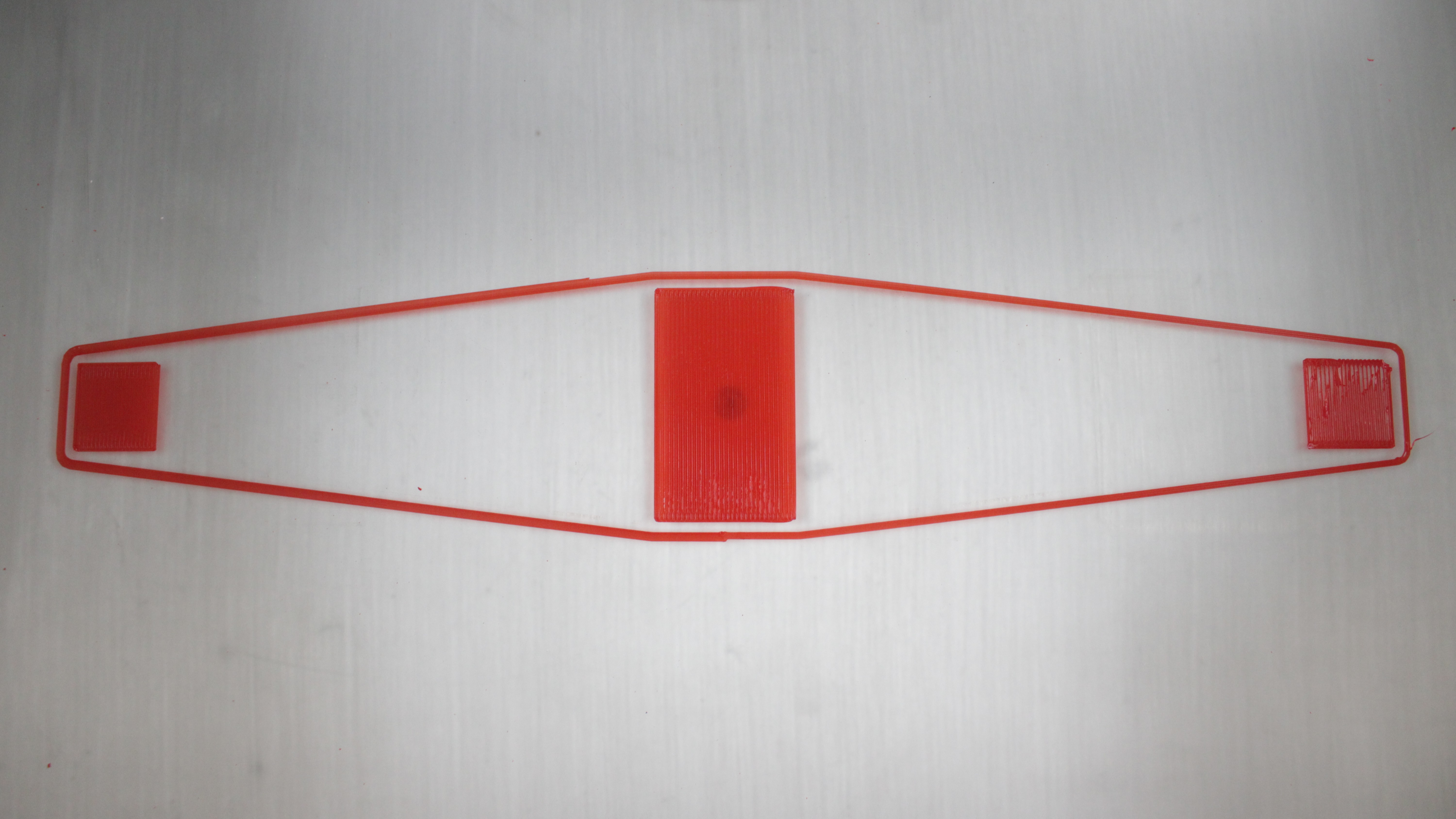
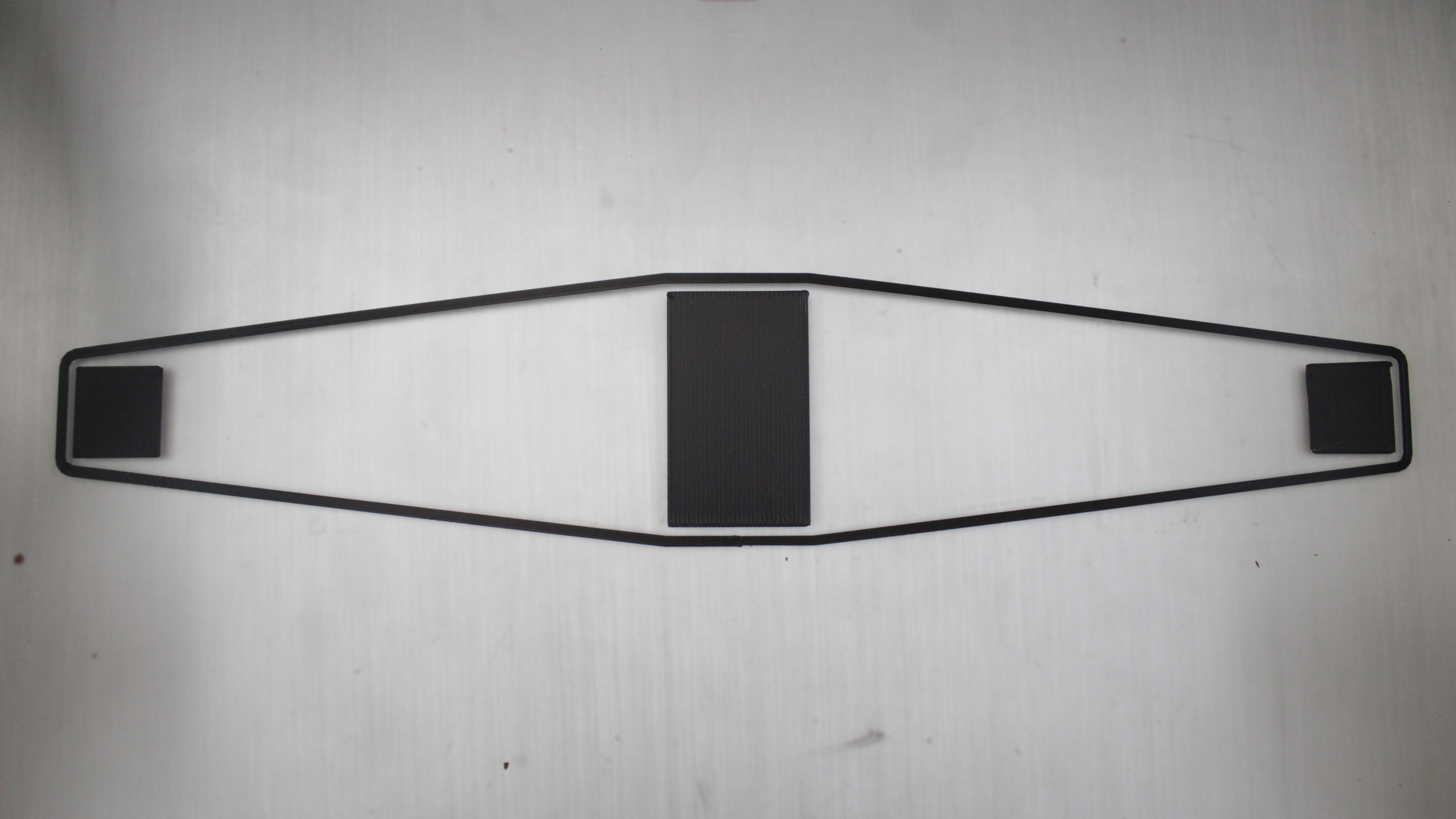
The test prints three small squares:
- Center square – use this to dial in your Z-offset
- Left square – checks the left side of the bed
- Right square – checks the right side of the bed
- Start the print.
- During the center square, adjust the Z Babystepping in the Web Interface (Status tab) until the first layer has perfect squish.
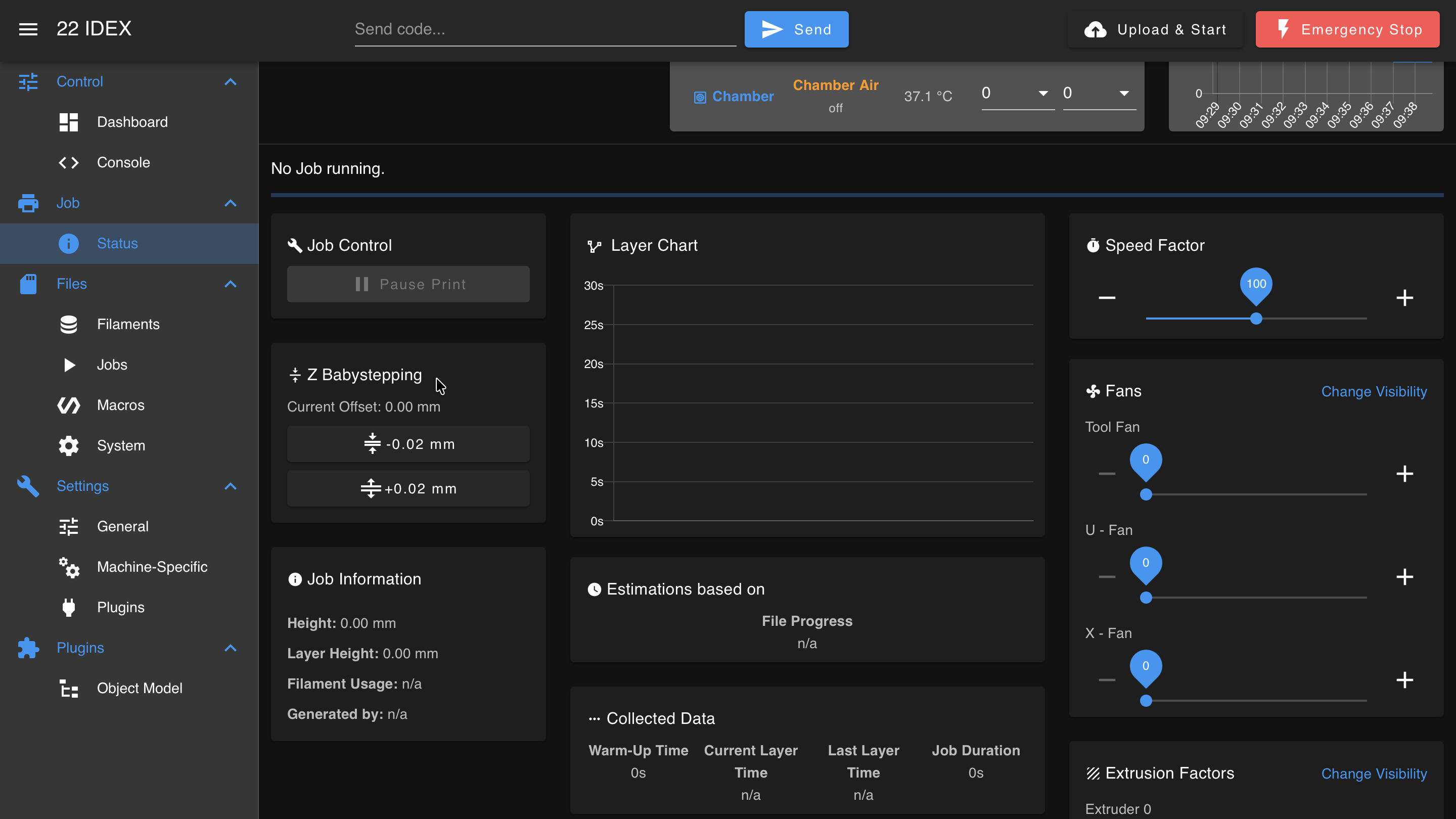
Once you achieve a good first layer on the center square, do not change the Z-offset again during this print. Leave it fixed so you can compare the left and right squares.
- Let the printer finish all three squares.
2. Manual Adjustment
Compare the squares
After the print completes, compare the three squares:
- The center square should have a perfect first layer (you set it with babystepping).
- The left and right squares should match the center square in squish and appearance.
If the left and right squares match the center: bed leveling is correct – no adjustment needed.
If one side is different, it is either too high or too low:
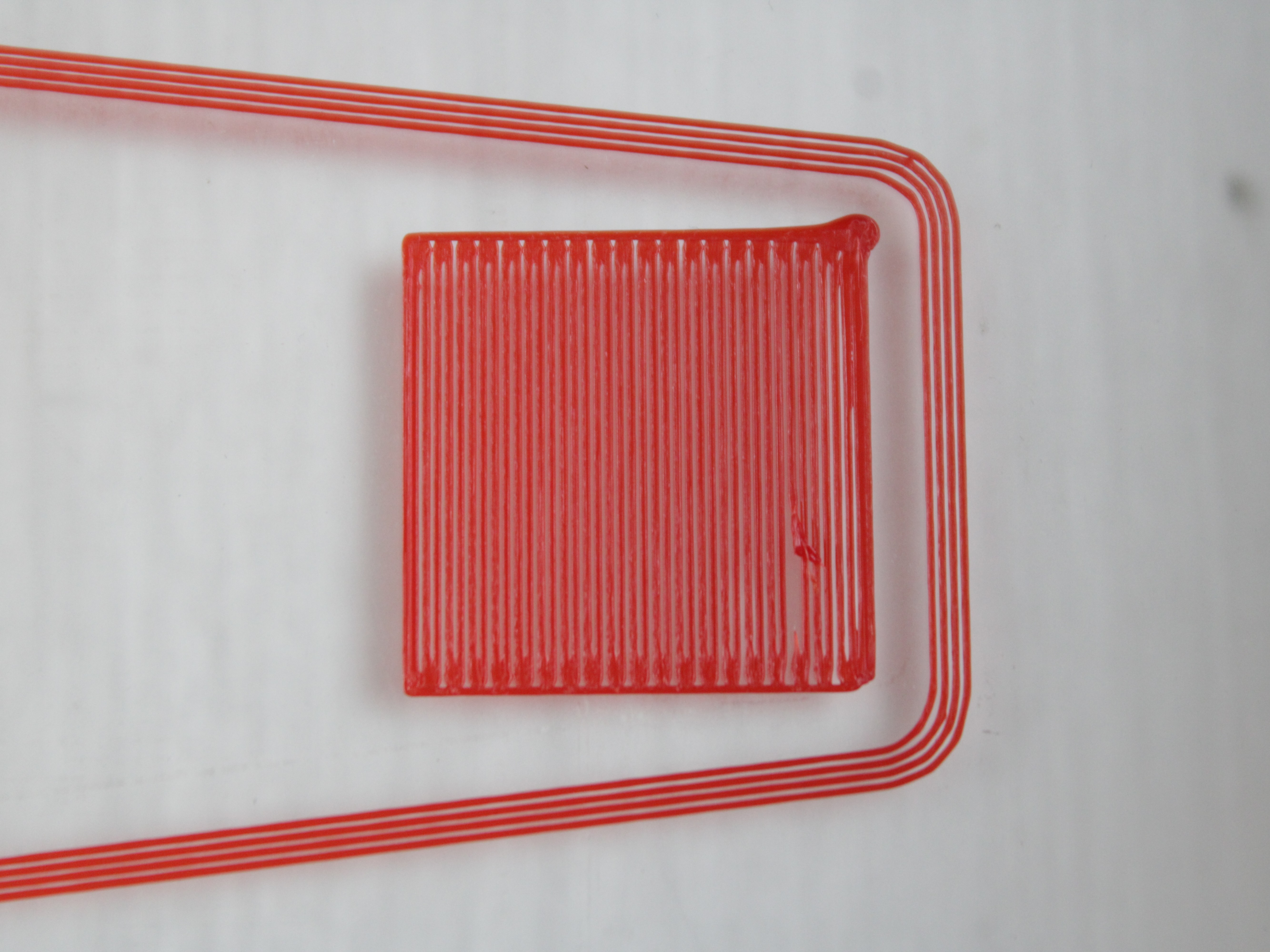
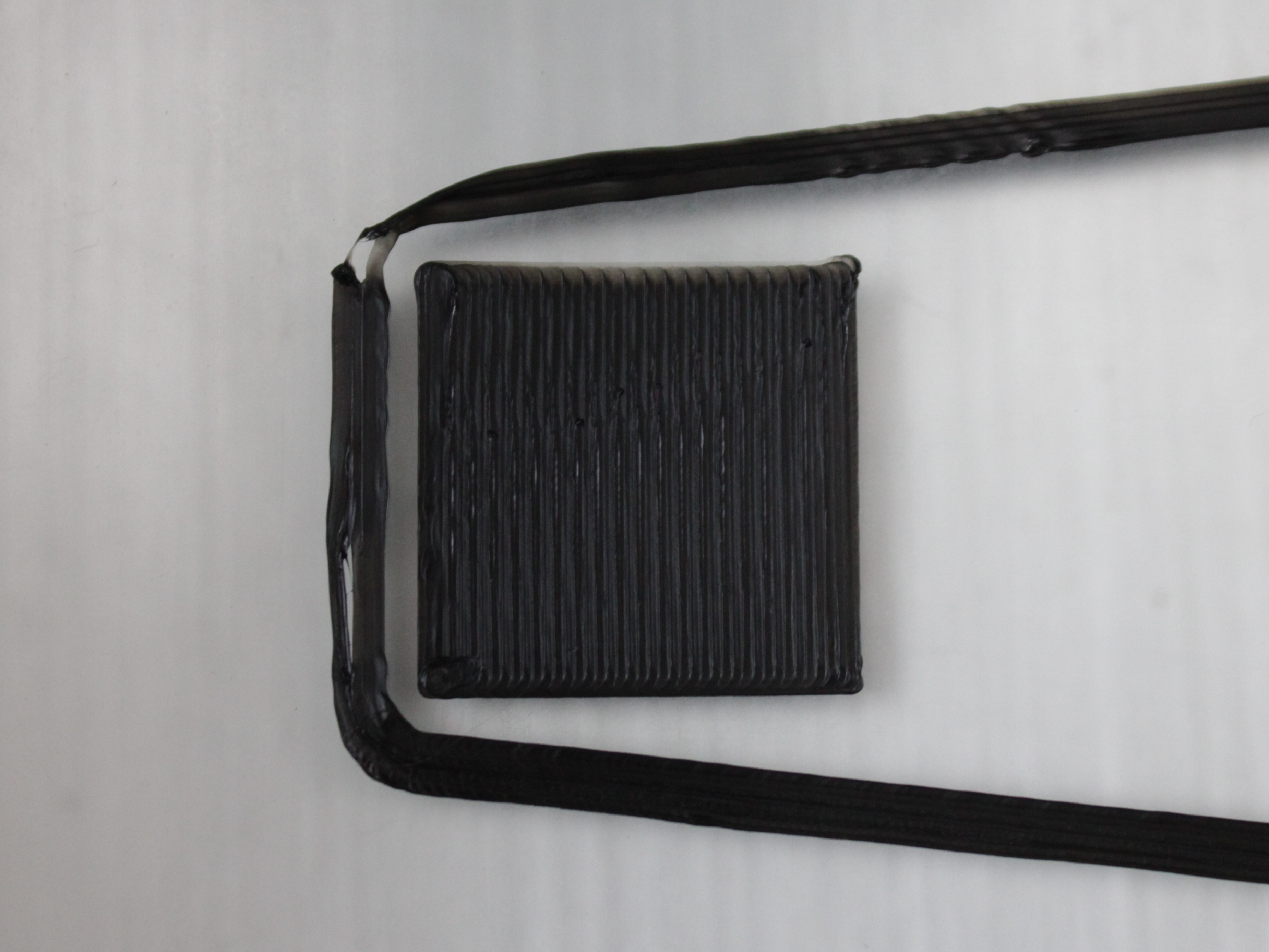
If one side is off, continue to the manual adjustment below.
Understanding the macros
Go to Macros > System > Calibration > Mesh Calibration/. You will see two adjustment macros:
| Macro | What it does |
|---|---|
| ↓_↑ RHS Up | Raises the right-hand side of the build plate by 0.04 mm (≈ 0.0016 in.) – brings the right side closer to the nozzle. |
| ↑_↓ RHS Down | Lowers the right-hand side of the build plate by 0.04 mm (≈ 0.0016 in.) – moves the right side farther from the nozzle. |
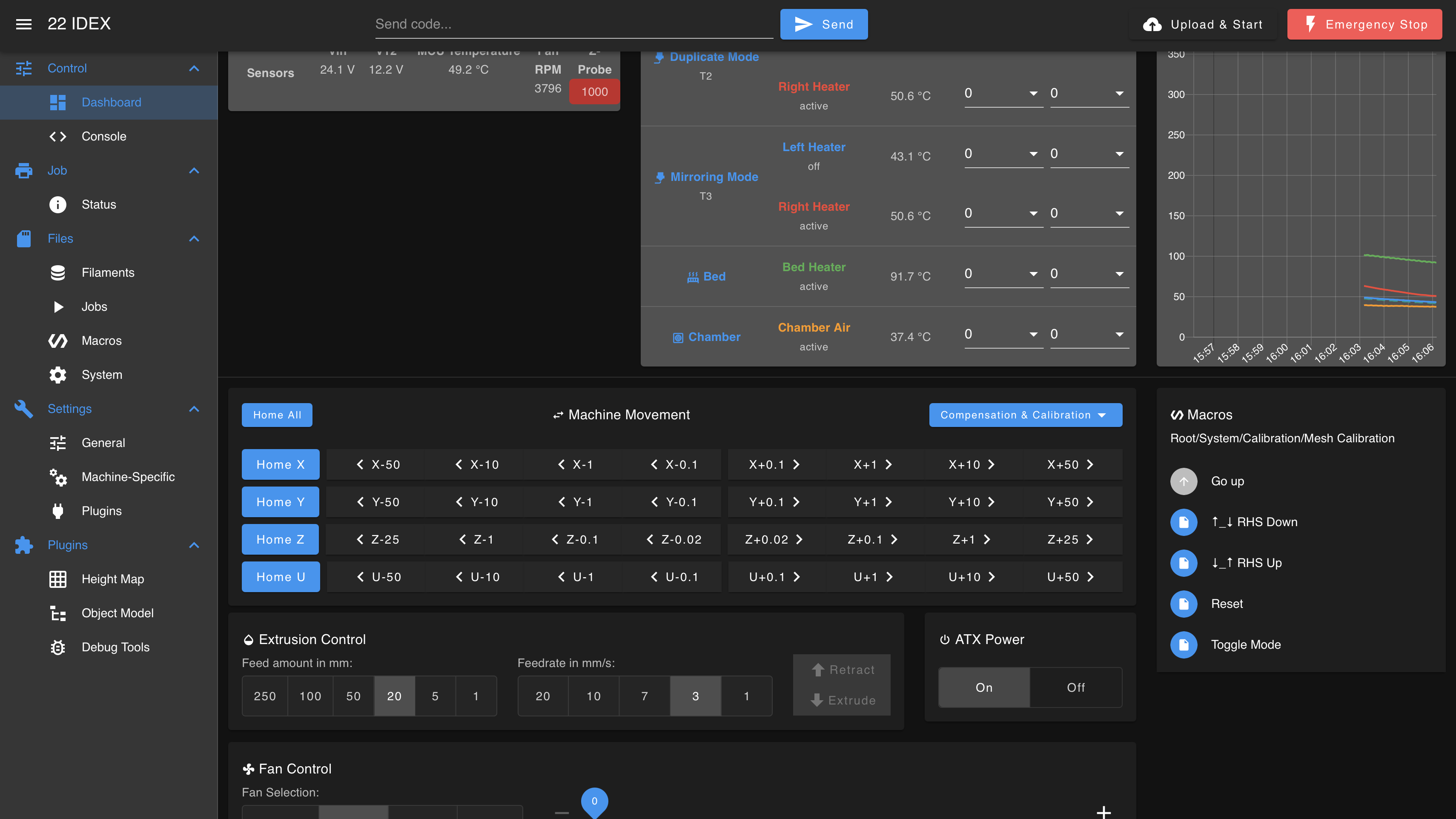
The bed tilts around the right-hand side, so adjusting one side affects the other – raising one side lowers the other. Make small, incremental changes and re-test. Usually a single press is enough.
Not a live change
RHS Up / RHS Down update the stored compensation value, and the printer applies it only at the start of the next print. Unlike Z Babystepping or tool offsets, which take effect immediately during a running print, pressing these macros has no visible effect on a print that is already in progress. Adjust between prints and re-run the 3-square test to see the result.
Match the macro to what you see:
- Right square too far (gaps) or left square too close (buildup) → ↓_↑ RHS Up (brings the right closer; the left drops slightly).
- Right square too close (buildup) or left square too far (gaps) → ↑_↓ RHS Down (moves the right farther; the left rises slightly).
Example adjustment workflow
Problem: The center square looks good. The right square is too close (filament buildup), and the left square is too far (gaps).
Solution: Use ↑_↓ RHS Down to lower the right side.
- Run the ↑_↓ RHS Down macro once.
- Re-run the 3-square test print.
- Adjust Z Babystepping on the center square if needed (it may shift slightly after mesh adjustment).
- Compare the left and right squares again.
- If still not perfect, repeat – adjust and re-test until all three squares match.
After adjustment:
FAQ
Support
If you could not find an answer here, reach out to our support team.