Wiring Schematic
Wiring schematic for the 22 IDEX V3 — mainboard and expansion board pinouts, motor drivers, endstops, Z-probe, heaters, fans and toolhead terminal blocks.
This article covers the complete wiring schematic of the Vision Miner 22IDEX V3. Use it as a reference when troubleshooting electrical connections, replacing components, or verifying wiring after maintenance. The printer uses two controller boards: a Duet 3 Mainboard 6HC (Board 0) and a Duet 3 Expansion 3HC (Board 1), connected via CAN-FD bus.
Before you begin - safety and risk
Read the Safety - Before You Begin article to understand the hazards involved in working on the Vision Miner 22IDEX V3 - including electrical, thermal, mechanical, and chemical risks. All procedures in this wiki are provided as recommendations only. By choosing to follow any procedure, you do so at your own risk.
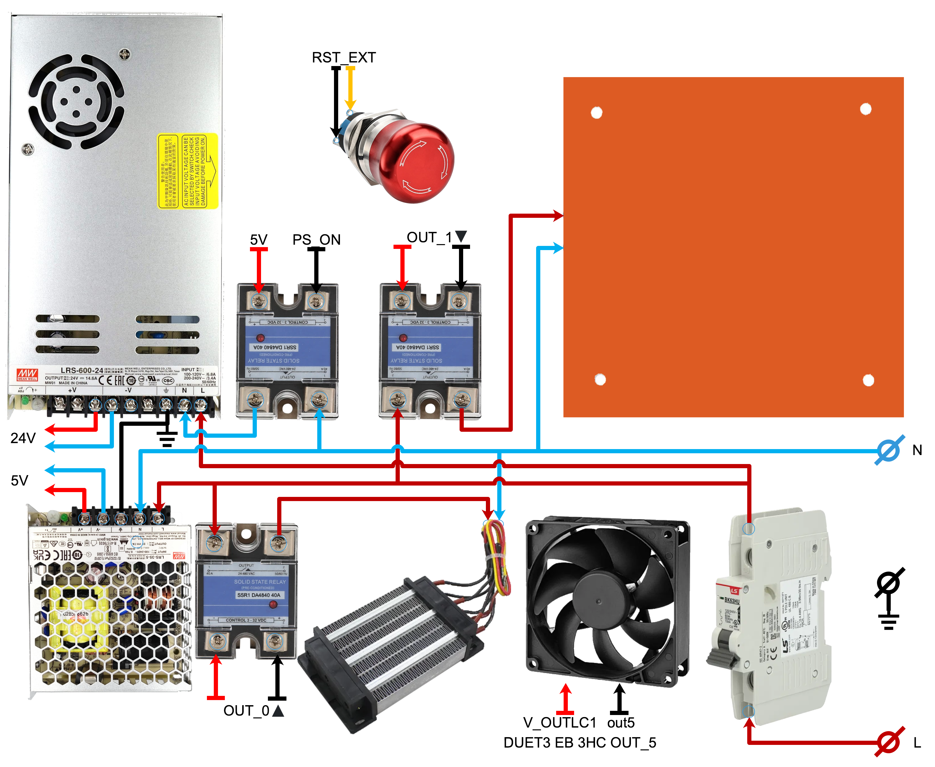
HV Wiring Schematic
High-voltage (mains) wiring between the power supply, SSR (solid-state relay), and the main board. This section is for reference only – do not service mains wiring yourself.
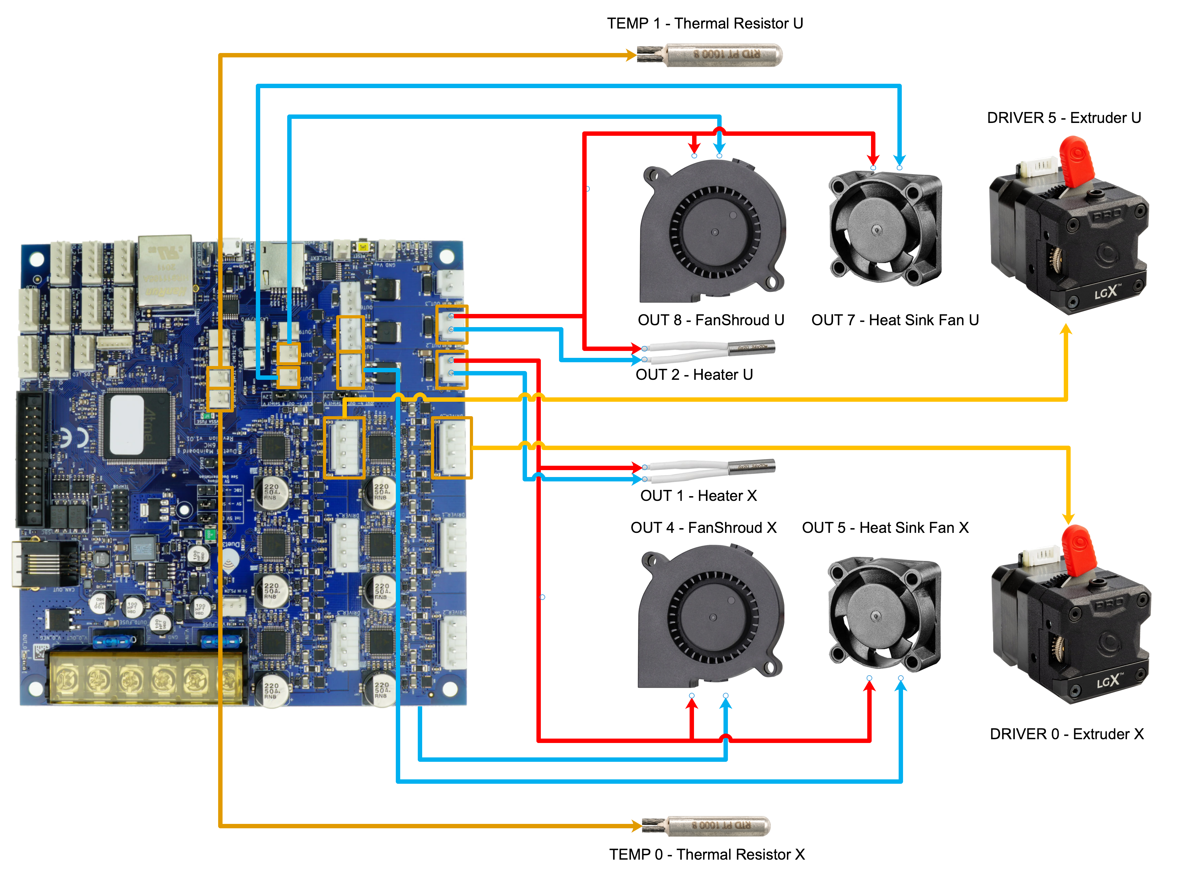
Heads – Main Board Connections
Hotend heaters, temperature sensors, and extruder motors connect to the Duet 3 MB 6HC (Board 0). Both toolheads (Left / Tool 0 and Right / Tool 1) wire back to this board.
Z Motors – Expansion Board Connections
The three Z-axis leadscrews are driven by motors connected to the Duet 3 Expansion 3HC (Board 1). The expansion board communicates with the main board over CAN-FD.
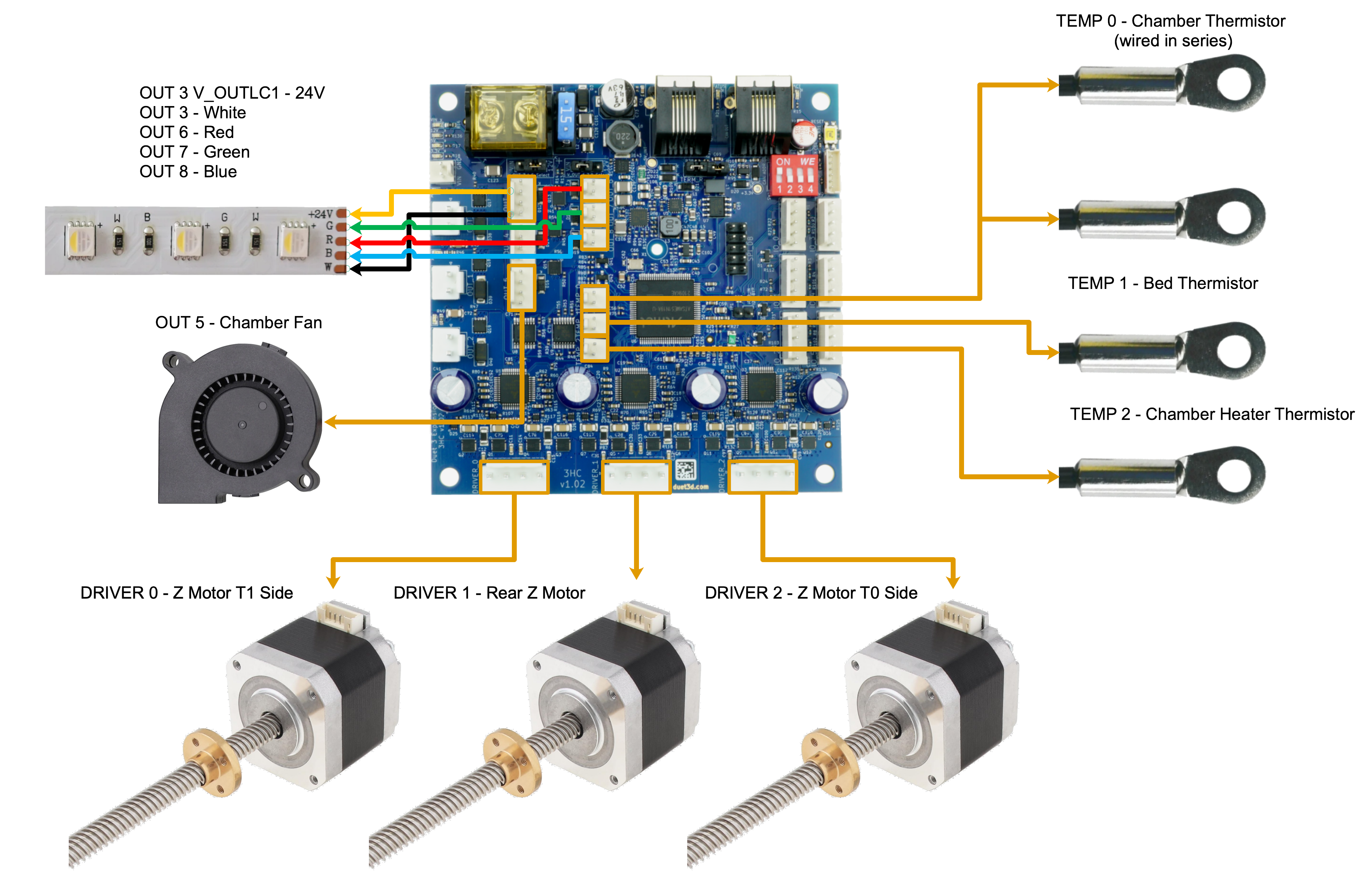
| Motor | Driver | Position |
|---|---|---|
| Z Motor 1 | 1.0 | Right leadscrew |
| Z Motor 2 | 1.1 | Rear leadscrew |
| Z Motor 3 | 1.2 | Left leadscrew |
X/Y/U Motors
The XY motion system uses four motors on the main board. Two Y-axis motors run in parallel on a shared axis.
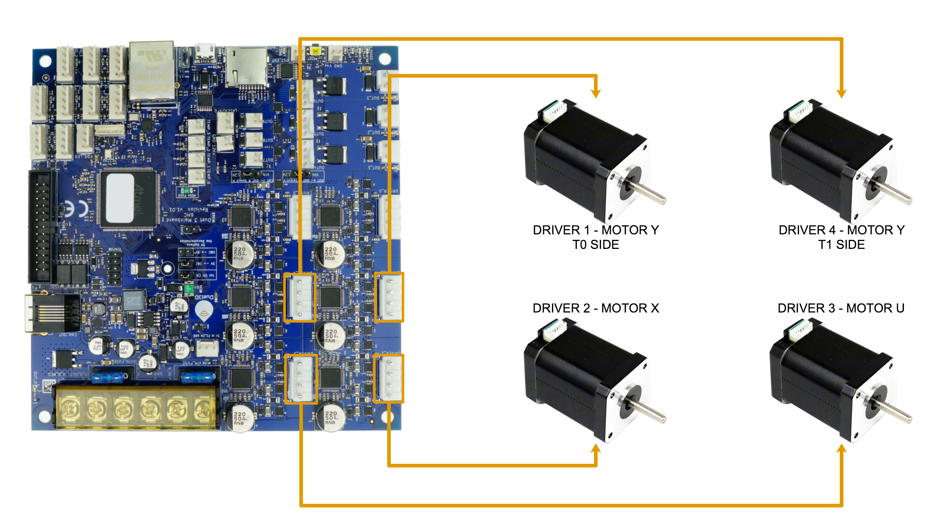
| Motor | Driver | Function |
|---|---|---|
| X motor | 0.2 | Tool 0 (left toolhead) movement |
| U motor | 0.3 | Tool 1 (right toolhead) movement |
| Y motor #1 | 0.1 | Y-axis (paired) |
| Y motor #2 | 0.4 | Y-axis (paired) |
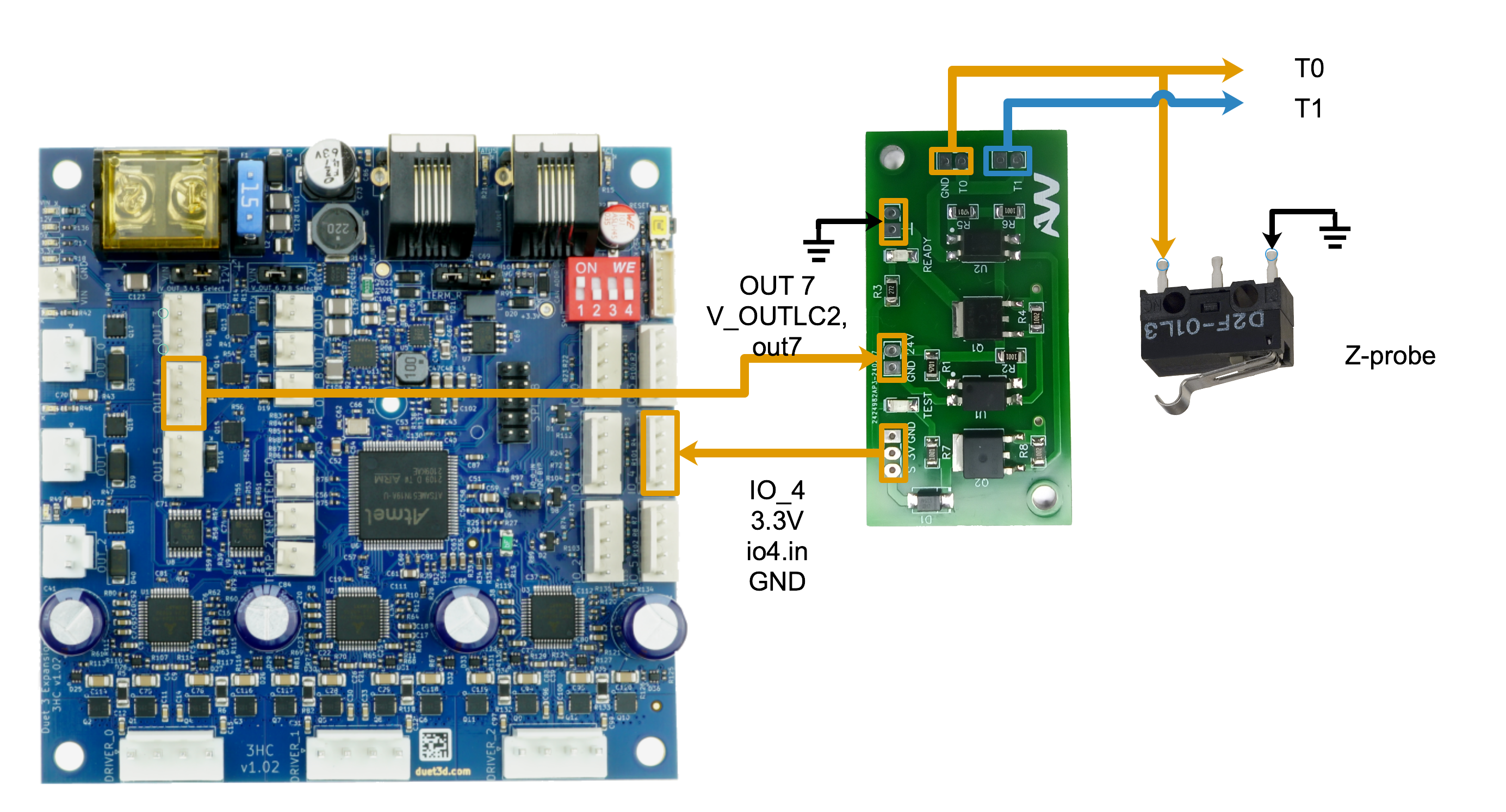
Z-Probe
The Z-probe is connected to the expansion board (Board 1) via 1.io4.in. Probe deployment and retraction are controlled by a servo motor driven from out9 on the main board. An ESD protection output is configured on 1.out4.
Switches
Endstop switch wiring for all axes. All endstop switches connect to IO headers on the main board.
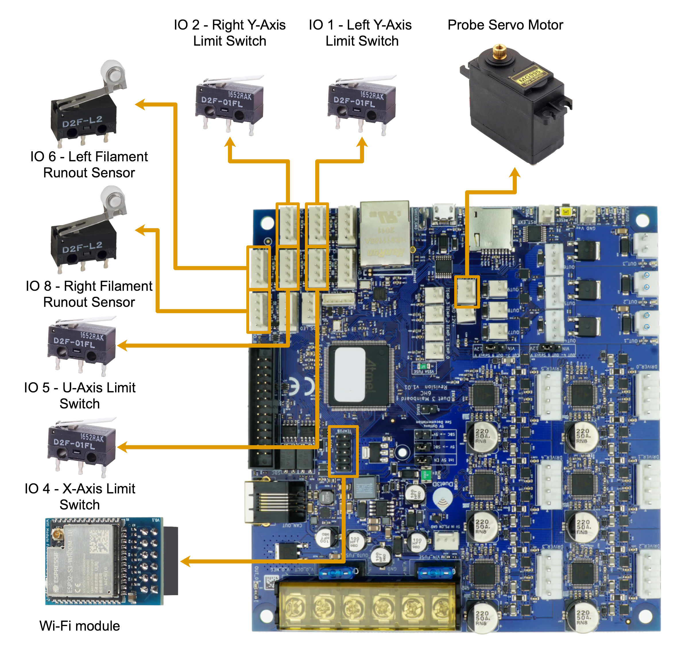
| Switch | Pin | Type |
|---|---|---|
| X endstop | io4.in | Min endstop (S1) |
| U endstop | io5.in | Max endstop (S1) |
| Y endstop #1 | io1.in | Min endstop (paired) |
| Y endstop #2 | io2.in | Min endstop (paired) |
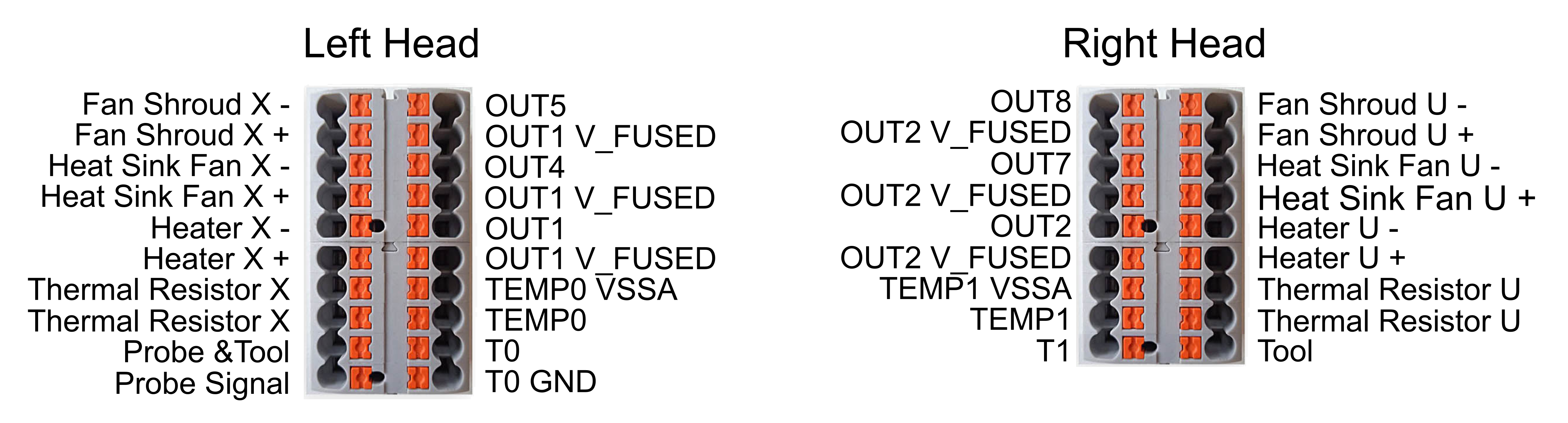
Toolhead Wiring
Terminal block connections for both toolheads, including heater wires, temperature sensor wires, fan wires, and extruder motor cables.
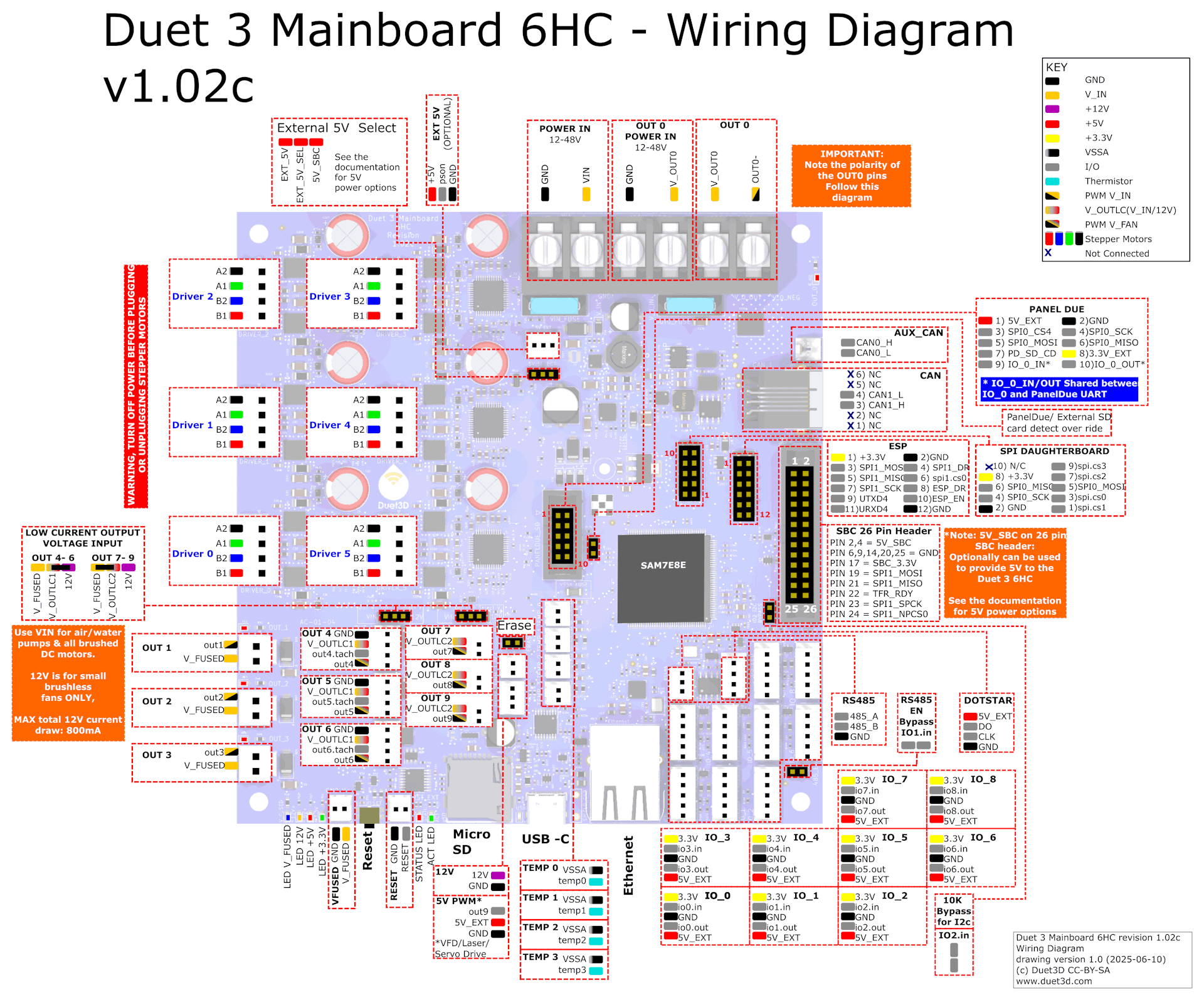
Main Board Pinout – Duet 3 MB 6HC (Board 0)
Complete pin assignment table for the main board. All pin names use RepRapFirmware notation.
Stepper Drivers
| Connector | RRF Pin | Axis | Function |
|---|---|---|---|
| DRIVER_0 | 0.0 | E0 | Left extruder motor |
| DRIVER_1 | 0.1 | Y | Y-axis motor #1 |
| DRIVER_2 | 0.2 | X | X-axis motor (Tool 0) |
| DRIVER_3 | 0.3 | U | U-axis motor (Tool 1) |
| DRIVER_4 | 0.4 | Y | Y-axis motor #2 |
| DRIVER_5 | 0.5 | E1 | Right extruder motor |
High / Medium Current Outputs
| Connector | RRF Pin | Function | Details |
|---|---|---|---|
| OUT1 | out1 | Left hotend heater (H0) | PT1000 sensor on TEMP_0 |
| OUT2 | out2 | Right hotend heater (H1) | PT1000 sensor on TEMP_1 |
| OUT4 | out4 | Left hotend cooling fan (F2) | Thermostatic, activates at 70 °C |
| OUT5 | out5 | X print cooling fan (F3) | User-controlled |
| OUT7 | out7 | Right hotend cooling fan (F0) | Thermostatic, activates at 70 °C |
| OUT8 | out8 | U print cooling fan (F1) | User-controlled |
| OUT9 | out9 | Z-probe servo (S0) | 50 Hz PWM |
Temperature Sensors
| Connector | RRF Pin | Function | Sensor Type |
|---|---|---|---|
| TEMP_0 | temp0 | Left hotend | PT1000 |
| TEMP_1 | temp1 | Right hotend | PT1000 |
Input / Output
| Connector | RRF Pin | Function |
|---|---|---|
| IO_1 | io1.in | Y endstop #1 |
| IO_2 | io2.in | Y endstop #2 |
| IO_4 | io4.in | X endstop |
| IO_5 | io5.in | U endstop |
Power Control
| Connector | RRF Pin | Function |
|---|---|---|
| EXT 5V | pson | Power supply on/off (M80/M81) |
Jumpers
The pinout diagram above shows where each jumper header sits on the board and what its pins are. The table below adds the part the diagram cannot show: which pins the jumper bridges on the 22 IDEX. Always compare with the new board before powering it on after a replacement.
| Jumper on the diagram | What it selects | Setting on the 22 IDEX |
|---|---|---|
| External 5V Select (above POWER IN) | Source of the 5V rail for the board | Jumper on the right-most and center pins (facing the board). See Main Board Replacement |
| OUT 4-6 voltage input (left edge) | Supply for the low-current fan outputs OUT4–OUT6: V_FUSED (24V) or 12V | Jumper on V_FUSED + V_OUTLC1 (24V fans) |
| OUT 7-9 voltage input (left edge) | Supply for OUT7–OUT9: V_FUSED (24V) or 12V | Jumper on V_FUSED + V_OUTLC2 (24V fans) |
| Erase (next to the SAM7E8E chip) | Erases the firmware when shorted | Open. Shorted only during Fallback Firmware Recovery (BOSSA) |
| RS485 EN Bypass (IO1.in), 10K Bypass for I2C (IO2.in) | Optional bypasses for IO1 / IO2 | Open, not used on the 22 IDEX |
Fan jumpers moved by mistake
The OUT 4-6 and OUT 7-9 jumpers are the ones you may borrow for the Erase step in the BOSSA procedure. If the hotend or part cooling fans stop working after that procedure, one of these jumpers went back onto the wrong pins. Power off and set them as in the table.
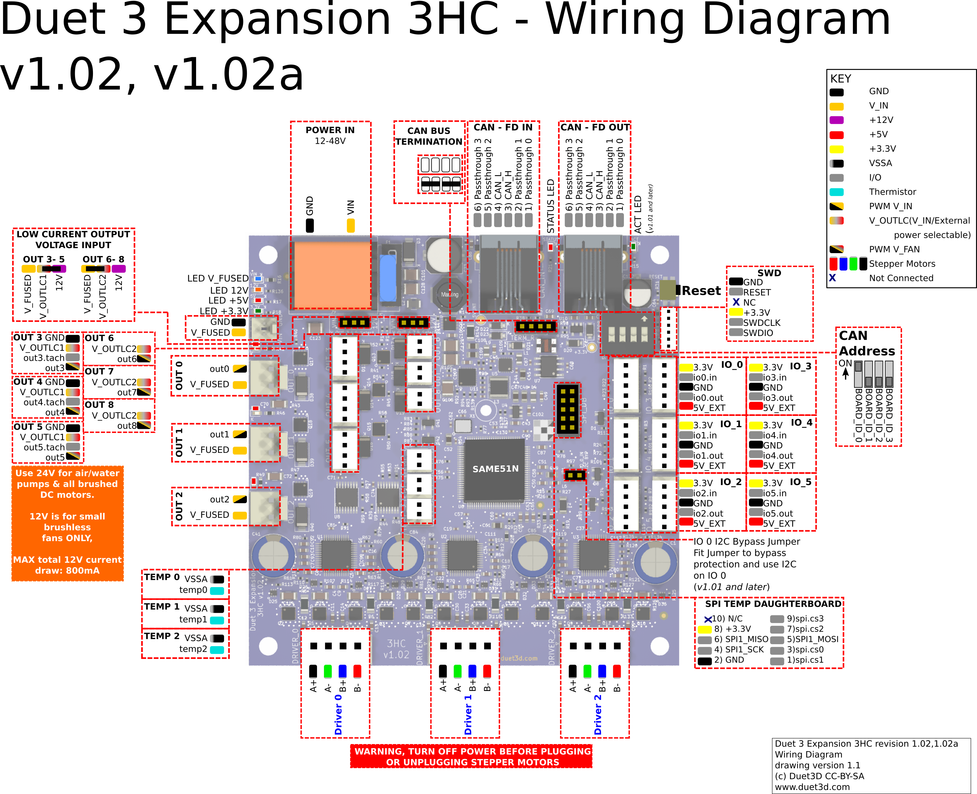
Expansion Board Pinout – Duet 3 EXP3HC (Board 1)
Complete pin assignment table for the expansion board, connected to the main board via CAN-FD (address 1).
Stepper Drivers
| Connector | RRF Pin | Axis | Function |
|---|---|---|---|
| DRIVER_0 | 1.0 | Z | Z motor – right leadscrew |
| DRIVER_1 | 1.1 | Z | Z motor – rear leadscrew |
| DRIVER_2 | 1.2 | Z | Z motor – left leadscrew |
Outputs
| Connector | RRF Pin | Function | Details |
|---|---|---|---|
| OUT0 | 1.out0 | Bed heater (H2) | 10 Hz PWM |
| OUT1 | 1.out1 | Chamber heater (H3) | 10 Hz PWM |
| OUT2 | 1.out2 | Chamber heater fan (F4) | Thermostatic, activates at 80 °C |
| OUT3 | 1.out3 | White LEDs (F6) | User-controlled |
| OUT4 | 1.out4 | Z-probe ESD protection | – |
| OUT6 | 1.out6 | Red LEDs | PWM, 5 kHz |
| OUT7 | 1.out7 | Green LEDs | PWM, 5 kHz |
| OUT8 | 1.out8 | Blue LEDs | PWM, 5 kHz |
Temperature Sensors
| Connector | RRF Pin | Function | Sensor Type | Parameters |
|---|---|---|---|---|
| TEMP_0 | 1.temp0 | Chamber air | Thermistor | 200 kΩ, B=3950 |
| TEMP_1 | 1.temp1 | Bed heater | Thermistor | 100 kΩ, B=3950 |
| TEMP_2 | 1.temp2 | Chamber heater | Thermistor | 100 kΩ, B=3950 |
Input / Output
| Connector | RRF Pin | Function |
|---|---|---|
| IO_4 | 1.io4.in | Z-probe input |
Jumpers
| Jumper on the diagram | What it selects | Setting on the 22 IDEX |
|---|---|---|
| OUT 3-5 voltage input (left edge) | Supply for the low-current outputs OUT3–OUT5: V_FUSED (24V) or 12V | Jumper on V_FUSED + V_OUTLC1 (left-most and center pins, 24V) |
| OUT 6-8 voltage input (left edge) | Supply for OUT6–OUT8: V_FUSED (24V) or 12V | Jumper on V_FUSED + V_OUTLC2 (left-most and center pins, 24V) |
Support
If you could not find an answer here, reach out to our support team.