Endstop Replacement
Replace an X, U or Y endstop on the 22 IDEX V4: routing the cable to the mainboard, swapping the printed Y holder, aligning both Y switches, and testing.
This guide covers replacing the X, U, and Y axis endstops on the Vision Miner 22IDEX V4. Replacement is the fix when the Endstop Issues diagnosis points to a faulty switch or a damaged mount. The endstops are supplied as complete assemblies - the switch together with its cable - and the 3D-printed holders are available separately.
Before you begin - safety and risk
Read the Safety - Before You Begin article to understand the hazards involved in working on the Vision Miner 22IDEX V4 - including electrical, thermal, mechanical, and chemical risks. All procedures in this wiki are provided as recommendations only. By choosing to follow any procedure, you do so at your own risk.
Tools and Materials
- Replacement endstop assembly for the affected axis:
- EndStop Sensor Assembly - X Axis T0 (X endstop)
- EndStop Sensor Assembly - X Axis T1 (U endstop)
- EndStop Sensor Assembly - Y Axis T0 (Left Y endstop)
- EndStop Sensor Assembly - Y Axis T1 (Right Y endstop)
- Replacement 3D-printed holder, if damaged: XU - Endstop Holder or Y - Endstop Holder, or print your own from the CAD Models article
- PH1 Phillips screwdriver (switch-to-holder screws)
- 2mm HEX - Wera Screw Driver (Y endstop front screws)
- 2.5 mm hex key (vertical cable channel cover)
- 4 mm hex key (lid spacer)
- PH2 Phillips screwdriver (LED clip screws, for Y endstop access)
- Flush cutters (for cutting zip ties)
- Zip ties (to secure the new cable)
Which Part to Replace
The endstop consists of two parts: the electrical part (the switch with its cable) and the 3D-printed holder it is mounted on. What you replace depends on the axis:
- X and U axes. The printed holder practically never fails - in 99% of cases you replace only the electrical part, the endstop assembly with its cable.
- Y axis. The 3D-printed part is the usual suspect. Inspect it first for cracks, warping, or breakage, and if it is damaged, replace the printed part and re-run the Endstops Test. If the printed part is intact, or replacing it did not help, replace the electrical part.
Overview
The endstop cable path is identical for the X, U, and Y endstops. The cables run along the top portal from the inside of the chamber to the electronics compartment at the rear of the machine. At the corner of the top portal there is a loop where three cables converge: the X (or U, depending on the side) endstop cable, the Y endstop cable, and the chamber LED cable. From there the cables run through the front part of the lid spacer, are secured with zip ties on the top portal, then pass under the top portal into the vertical metal cable channel on the rear of the machine and go down the channel to the mainboard, where they plug in. See the Wiring Schematic for the full pinout.
The replacement is done in two stages: free the switch and its cable at the front, then release the cable along the rear path and disconnect it.
Power off before you start
Turn the printer off and unplug the power cord before disconnecting or routing any wiring. Wait at least 60 seconds for the capacitors to discharge before touching any connectors on the boards.
Replacing the X or U Endstop
Removing the Old Endstop
- Unscrew the printed holder. Unscrew the 3D-printed endstop holder from the machine.
- Unscrew the switch from the holder. The switch is held in the holder by two screws under a PH1 screwdriver. Unscrew them and take the switch off.
- Free the cable at the front. Take the endstop cable out of the loop at the corner of the top portal - the one shared by the X/U endstop, Y endstop, and LED cables. Then remove the front part of the lid spacer: unscrew its two screws with the 4 mm hex key, take the front part out forward, and free the endstop cable sitting in it. If you have already removed the front part of the lid spacer - for example, while replacing another endstop - skip this part of the step. Then lift the cable out of the groove at the edge of the top portal, where it runs along the lid clip.
- Pass the cable to the rear. Open the electronics compartment with the rear doors. Feed the freed cable through the gap between the lid and the body towards the rear of the printer. Along the way, cut the zip ties that secure the endstop cable to the top portal. The endstop switch is small, so it passes through the gap easily - there is nothing bulky to get stuck.
- Open the rear cable channel. The vertical cable channel cover is fastened with six screws - unscrew them with the 2.5 mm hex key and remove the cover.
- Cut the zip ties along the cable path. Visually follow the endstop cable down the channel and cut the zip ties that bind it to the other cables, one by one, all the way towards the board.
- Disconnect the cable. Locate the connector of the endstop on the mainboard and unplug it. Before unplugging, take a photo of the connections so you know exactly what goes where during reassembly, or use the wiring diagram below as the reference - it shows exactly which connector on the board belongs to which endstop. With the cable disconnected and freed, the whole assembly comes out at the rear of the printer.
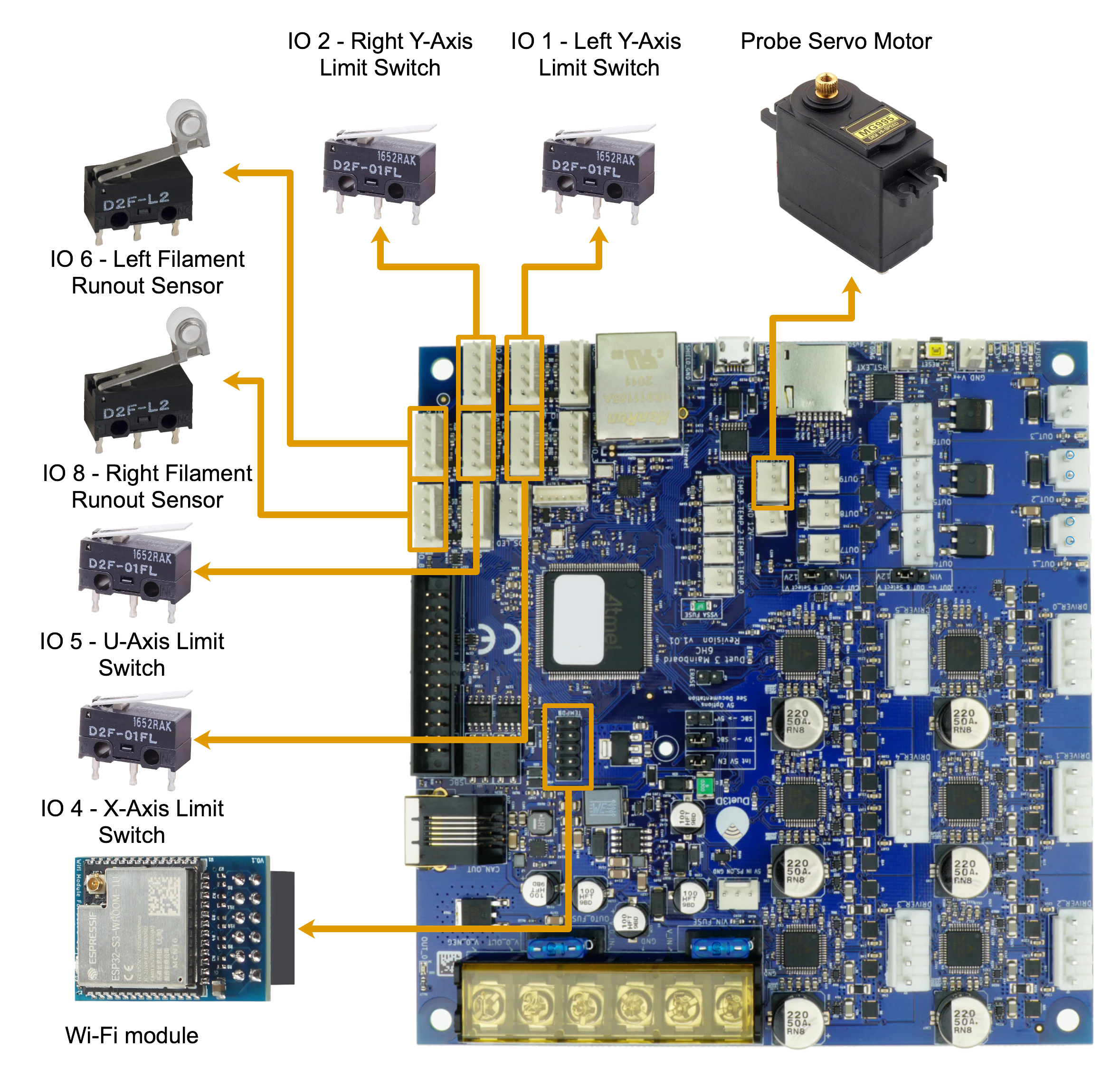
Installing the New Endstop
-
Feed the new cable in from the rear. Route the new endstop cable the same way the old one came out: up the vertical cable channel, under the top portal, and through the gap between the lid and the body towards the front.
-
Mount the switch. Screw the switch into the printed holder with its two PH1 screws and fasten the holder back on the machine. Pay attention to the orientation: the switch body is a rectangular block, but its button sits off-center, so the switch fits into the holder in two positions - with the button slightly to the left or slightly to the right. Install it so the button is closer to the doors of the machine - only then can the X/U head reach the endstop.
-
Lay the cable into its path. Seat the cable in the loop at the corner of the top portal and in the groove at the edge of the portal. Seat it in the front part of the lid spacer together with the other cables, put the front part back, and tighten its two screws with the 4 mm hex key. Set the cable so it is not bent sharply anywhere.
-
Connect at the mainboard. Plug the cable into the mainboard - using the photo you took before removal or the wiring diagram above. Do not secure anything with zip ties yet.
-
Check before you close up. Run through the Verification section below. Only when the endstop passes the test, power off again, secure the cable with new zip ties - to the top portal and along the channel - reinstall the cable channel cover with its six screws, and close the rear doors.
Replacing a Y Endstop
The Left Y and Right Y endstops are mounted on 3D-printed holders and fastened with two screws on the front part of the machine. There are two repair paths: replacing only the damaged 3D-printed holder, or replacing the whole electrical assembly. Both start the same way - the chamber LED strip must come out of the way and the endstop must come off the machine, even if you are only swapping the printed part.
Getting to the Y Endstop
- Release the LED strip. Follow steps 1-2 of the LED Replacement removal procedure: loosen the two clip screws per clip, pop the strip out of its clips, and remove the front part of the lid spacer. The strip stays connected - it just hangs out of the way. The Y endstop is now visible from the front.
- Unscrew the Y endstop. On the front part there are two screws under the 2 mm hex screwdriver. Unscrew them and the endstop body comes down.
- Unscrew the cable clamps. Under the side wall there is a row of four screws. They hold the zip-tie loops that clamp the endstop cable. Each screw sits on top with a nut underneath the portal - find the nut with your eyes before unscrewing, and if it spins, hold it with your hand. Unscrew at least three of the four so you can bring the Y endstop out and get proper access to it.
- Inspect the 3D-printed holder. Look for cracks, warping, or breakage. If the printed part is damaged, continue with Replacing Only the 3D-Printed Holder below. If the holder is intact, go straight to Replacing the Electrical Part.
Replacing Only the 3D-Printed Holder
- Move the switch to a new holder. Order a Y - Endstop Holder or print one from the Y-EndStop model (the same part fits both sides). Partially disassemble the endstop: unscrew the two PH1 screws holding the switch on the damaged holder and screw the switch onto the new one. The holder is symmetrical so that one part fits both the left and the right side, and because of that it has two pairs of holes - on each side, only one pair is correct. Screw the switch into the pair of holes where its button protrudes beyond the printed part, so the carriage that presses it can reach it. If the switch sits in the wrong pair, the carriage will press against the printed part and never reach the switch. The cable stays connected and in its path.
Install the holder the right way around and mind the cable
Mount the printed part on the printer exactly the way the old one was installed. If the holder goes on the wrong side, the Y axis will run its homing without ever contacting the switch - which leads to mechanical damage. Route the cable exactly as before as well: a mispositioned cable gets mechanically damaged over time.
- Reinstall and test. Fasten the endstop back on the front part with its two 2 mm hex screws, screw the cable clamps back, and re-run the Endstops Test. If the endstop now works, continue with Aligning the Y Endstops (step 22) and finish with reassembly. If it still fails, continue with the electrical part below.
Replacing the Electrical Part
- Free the cable at the front. Unscrew the last of the four cable clamp screws. Take the cable out of the loop at the corner of the top portal - the Y endstop sits right next to it - and lift it out of the groove at the edge of the portal. The front part of the lid spacer is already off from step 13; if yours is still in place, remove it as described in step 3.
-
Release the cable along the rear path and disconnect it. From here the process is identical to the X/U endstop - follow steps 4-7: pass the cable to the rear through the gap between the lid and the body, open the vertical cable channel, cut the zip ties along the path, and unplug the cable from the mainboard using the wiring diagram as the reference.
-
Install the new Y endstop. Route the new cable in from the rear (step 8). Mount the switch on the holder with its two PH1 screws, fasten the endstop on the front part with its two 2 mm hex screws, and screw the cable clamps back with their four screws, holding the nuts underneath. Lay the cable into its path and connect it at the mainboard (steps 10-11).
Aligning the Y Endstops
Do this alignment whenever the Y endstops have been unscrewed - after a holder replacement as well as after a full replacement. The Left Y and Right Y endstops must trigger at the same moment, otherwise the crossbar homes skewed. 22. Set the starting position. The mounting holes of the Y endstops are oval, which allows position adjustment. Slide both endstops as far toward the rear wall as the holes allow and tighten their screws.
- Check the click synchronization. Slowly bring the crossbar toward the endstops by hand and listen to the clicks of the two switches - they must click at the same moment. If the clicks are not synchronous, shift one of the endstops within its oval holes and check again, until both endstops click in sync.
- Reassemble. Snap the LED strip back into its clips and tighten the clip screws. Seat the endstop cable together with the LED cables in the front part of the lid spacer and reinstall it with its two screws. Run through the Verification section before securing the cable with zip ties and closing up.
Verification
- Plug the printer back in and power it on.
- Run the Endstops Test macro: Macros → System → Troubleshooting → Endstops Test. Follow the prompts and confirm the replaced endstop registers all 10 presses. See Endstop Issues for the full test procedure.
- After a Y endstop replacement, run the Home Y test to verify the Y endstops are parallel and positioned correctly: Macros → System → Calibration → QC → Tests → Home Y.
- Run the Probe Calibration to calibrate the probe position: Macros → System → Calibration → Z Probe → Probe Calibration.
- Run Auto Calibration - it is recommended after replacing any axis endstop, since the home position may have shifted slightly.
- If everything works, power off, secure the cables with zip ties, and close up the cable channel as described above.
FAQ
Support
If you could not find an answer here, reach out to our support team.