Unresponsive Printer
Printer will not start or reports VIN is not in range on the 22 IDEX V4 — check power supply and mainboard LEDs, then test and replace the blown 15A VIN fuse.
This guide covers how to diagnose a Vision Miner 22 IDEX V4 that will not start, does not respond to commands, or shows a "VIN is not in range" error. The two most common causes are a blown fuse on the mainboard and a corrupted micro-SD card that prevents the controller from booting.
Work through the diagnostic steps in order: check power delivery first, then inspect fuses. If the board is powered but still will not boot, the firmware on the SD card is the likely culprit – the fix is covered in the separate SD Card & Firmware Recovery guide.
Before you begin - safety and risk
Read the Safety - Before You Begin article to understand the hazards involved in working on the Vision Miner 22IDEX V4 - including electrical, thermal, mechanical, and chemical risks. Mains voltage is present inside the electronics bay. All procedures in this wiki are provided as recommendations only. By choosing to follow any procedure, you do so at your own risk.
Unplug, wait, and discharge static
Turn off the printer, unplug mains, and wait at least 60 seconds before touching the mainboard. Use an anti-static wrist strap or touch grounded metal before handling boards.
Tools and Materials
- Multimeter with continuity/beep mode
- 15A replacement fuses (×2)
- Needle-nose pliers or fuse puller
- Anti-static wrist strap (recommended)
1. Checking Power Supply LEDs
Before opening anything, verify that power is reaching the electronics. The Vision Miner 22 IDEX V4 has two power supplies and three solid-state relays (SSRs) on the right side of the electronics bay.
- Turn off the printer.
- Open both rear doors of the enclosure to access the electronics bay.
- Power the printer on.
- Look at the right side of the electronics bay. You should see two LEDs:
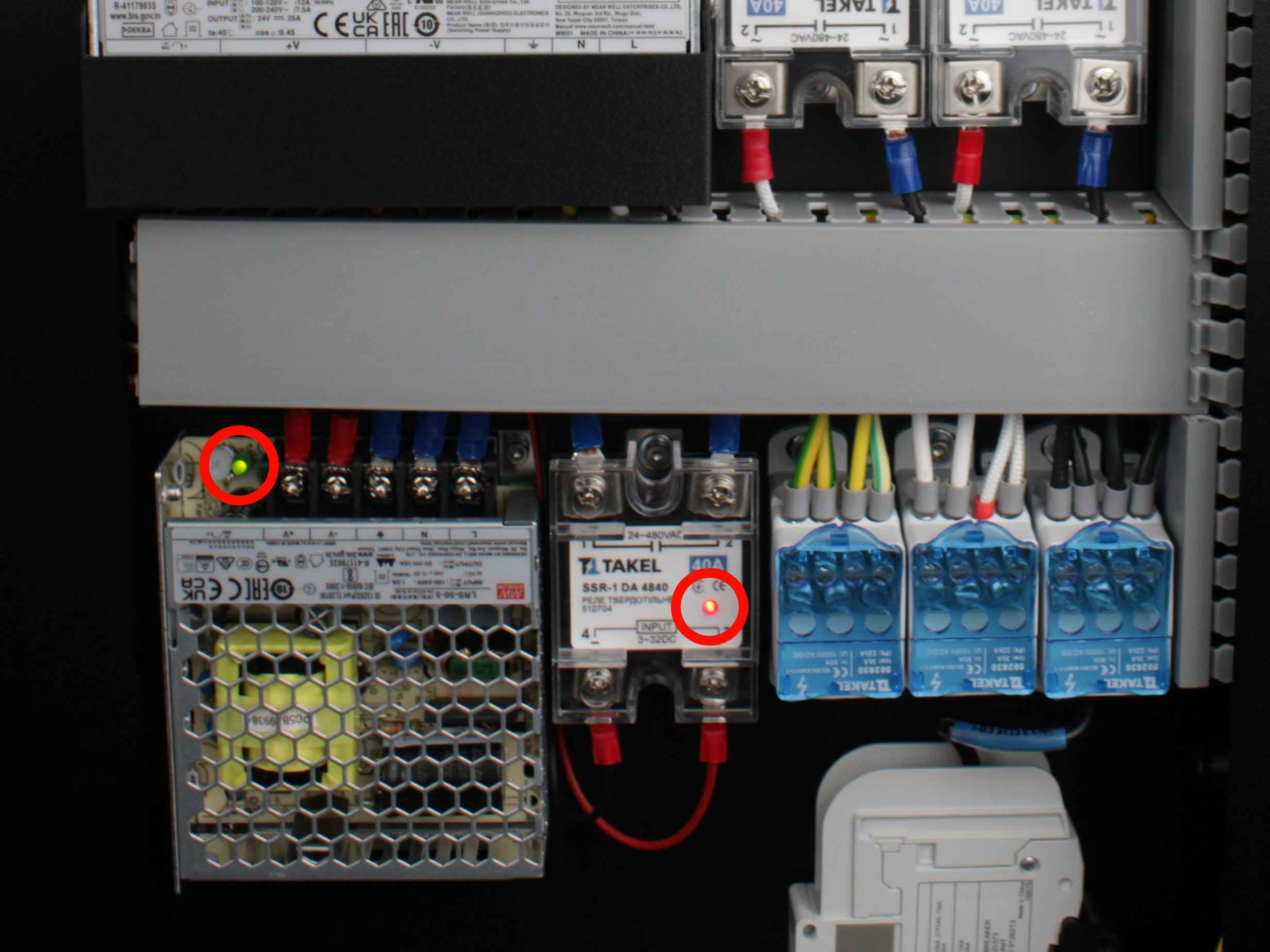
| Location | Expected LED | Meaning |
|---|---|---|
| 5V power supply (small PSU) | Green | 5V rail is active |
| Bottom solid-state relay | On | Main power-up relay is energized |
- If either of these two LEDs is missing, the problem is upstream of the mainboard - check the mains cable, the power inlet connector, and the SSR connections. See the Wiring Schematic for reference.
- If both LEDs are lit, continue to the next section.
2. Checking Mainboard and Expansion Board LEDs
The mainboard (Duet 3 MB 6HC) and expansion board (Duet 3 EXP3HC) are on the left side of the electronics bay. Each board has diagnostic LEDs that show which voltage rails are active.
- Look at the mainboard (upper board on the left side). Check the power indicator LEDs in the upper-right area of the board:
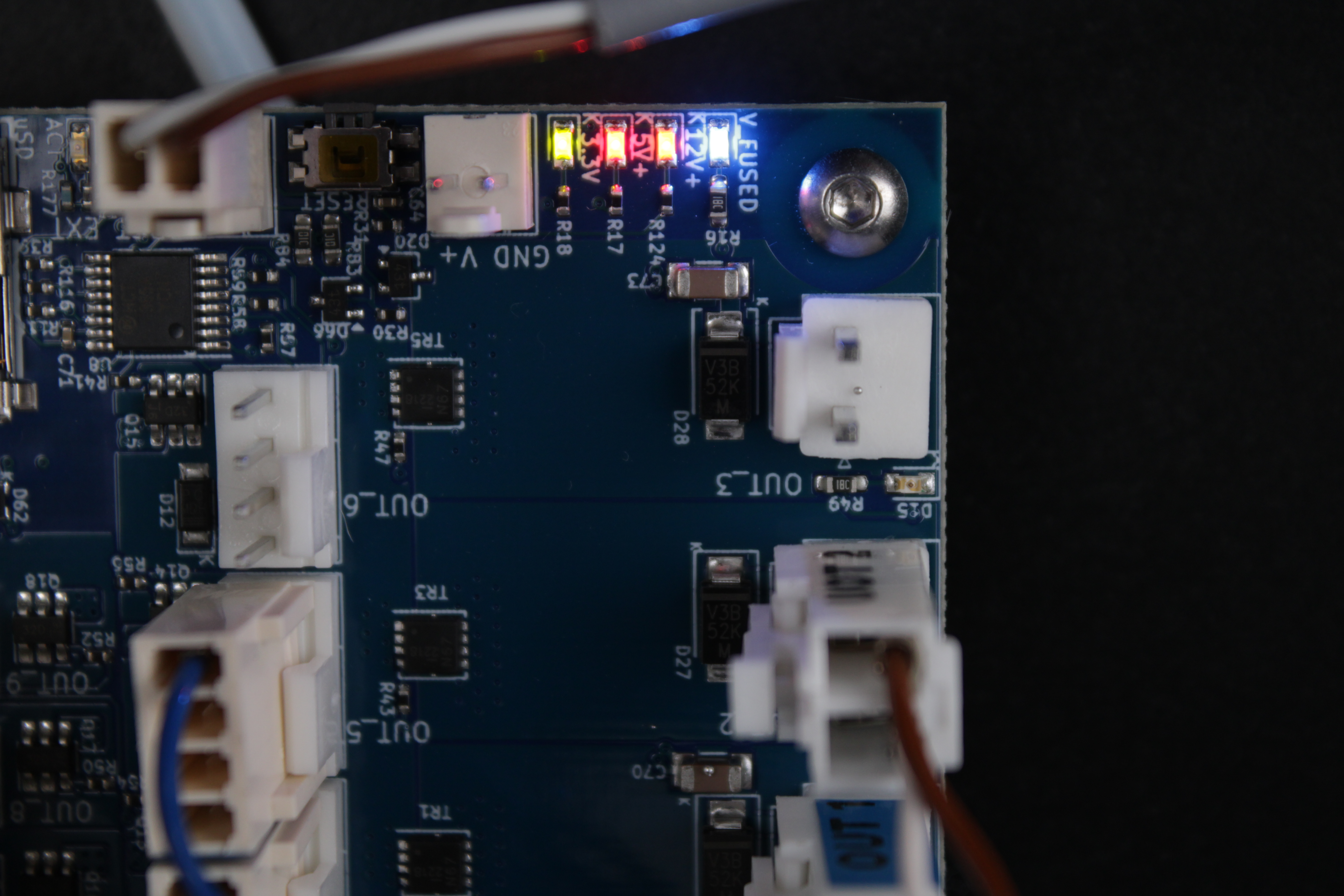
| LED Color | Voltage Rail | Expected State (V4) |
|---|---|---|
| Blue | 24V (V_FUSED) | On |
| Red | 5V | On |
| Green | 3.3V | On |
| Amber | 12V | Off - not used in standard V4 configuration |
- Also check the STATUS LED on the mainboard:
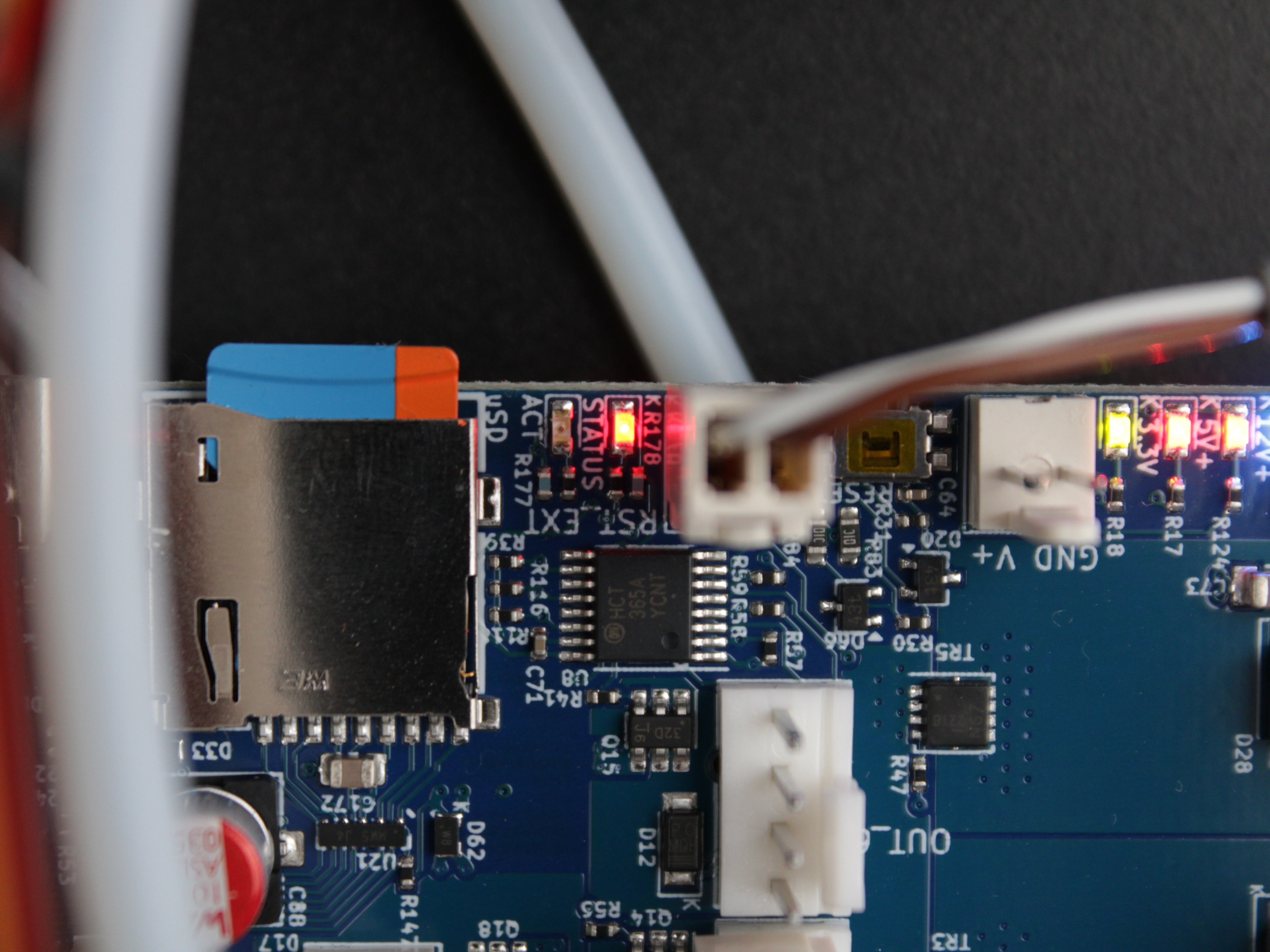
| STATUS LED Behavior | Meaning |
|---|---|
| Flashing steadily (0.5s on / 0.5s off) | Normal - RepRapFirmware is running |
| Dim or off | Firmware has been erased |
| Flashing 3×, then off | Firmware CRC check failed |
- Check the expansion board (lower board on the left side). It has the same set of power indicator LEDs - blue (24V), red (5V), green (3.3V), amber (12V). When connected to a running mainboard, the expansion board's diagnostic LED will blink in sync with the mainboard STATUS LED.
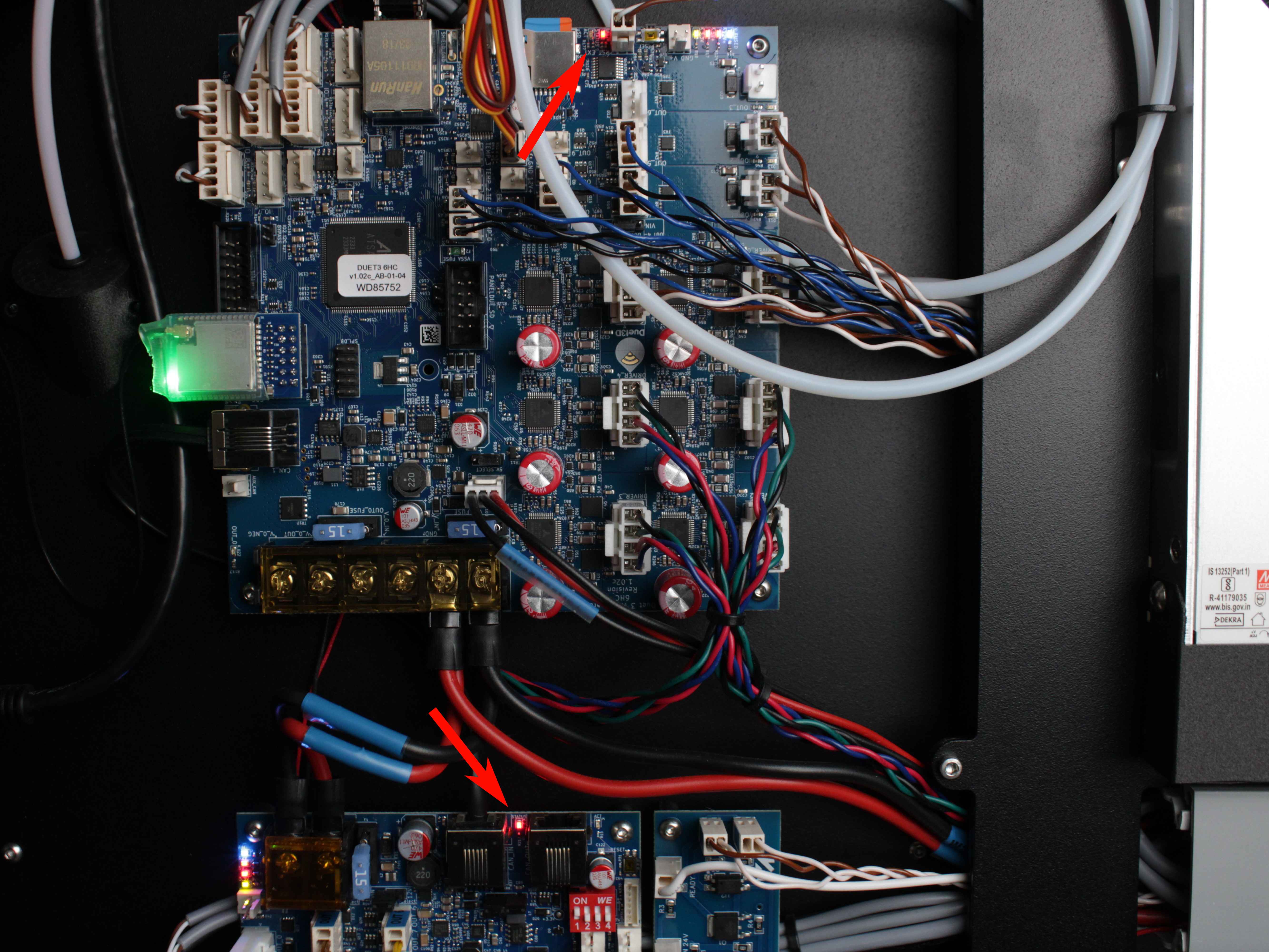
- Interpret the results:
- Blue (24V) LED is off on the mainboard, but the 24V PSU LED is green - the V_FUSED fuse is likely blown. Go to Section 3.
- All power LEDs are correct, STATUS LED flashes steadily, but the Web Interface does not load - check your network connection first. The printer may be in Wi-Fi Access Point mode (SSID: 22 IDEX or the machine's custom name, password 1234567890, printer address 192.168.0.1).
- All power LEDs are correct, but STATUS LED is dim/off or flashing 3× - the firmware is missing or corrupt. Continue with the SD Card & Firmware Recovery guide.
3. Checking and Replacing Fuses
The Duet 3 MB 6HC mainboard has two user-serviceable fuses:
| Fuse | Rating | Protects |
|---|---|---|
| V_FUSED | 15A | Main VIN supply - motor drivers, heaters, and most board circuits |
| OUT0 | 15A | High-current output (e.g., heater) |
A blown V_FUSED fuse cuts power to the motor drivers and most circuits on the board. This is the most common cause of the "VIN is not in range" error and non-responsive X/Y axes.
Possible cause: tangled filament on the spool stalls an extruder motor. The stalled motor draws excessive current, overloads the circuit, and blows the V_FUSED fuse. This is especially common with rigid high-temperature filaments (PEEK, PEI, PEKK) that tend to unwind and tangle.
- Turn off the printer and unplug it from the power outlet.
- Locate the two fuses on the mainboard.
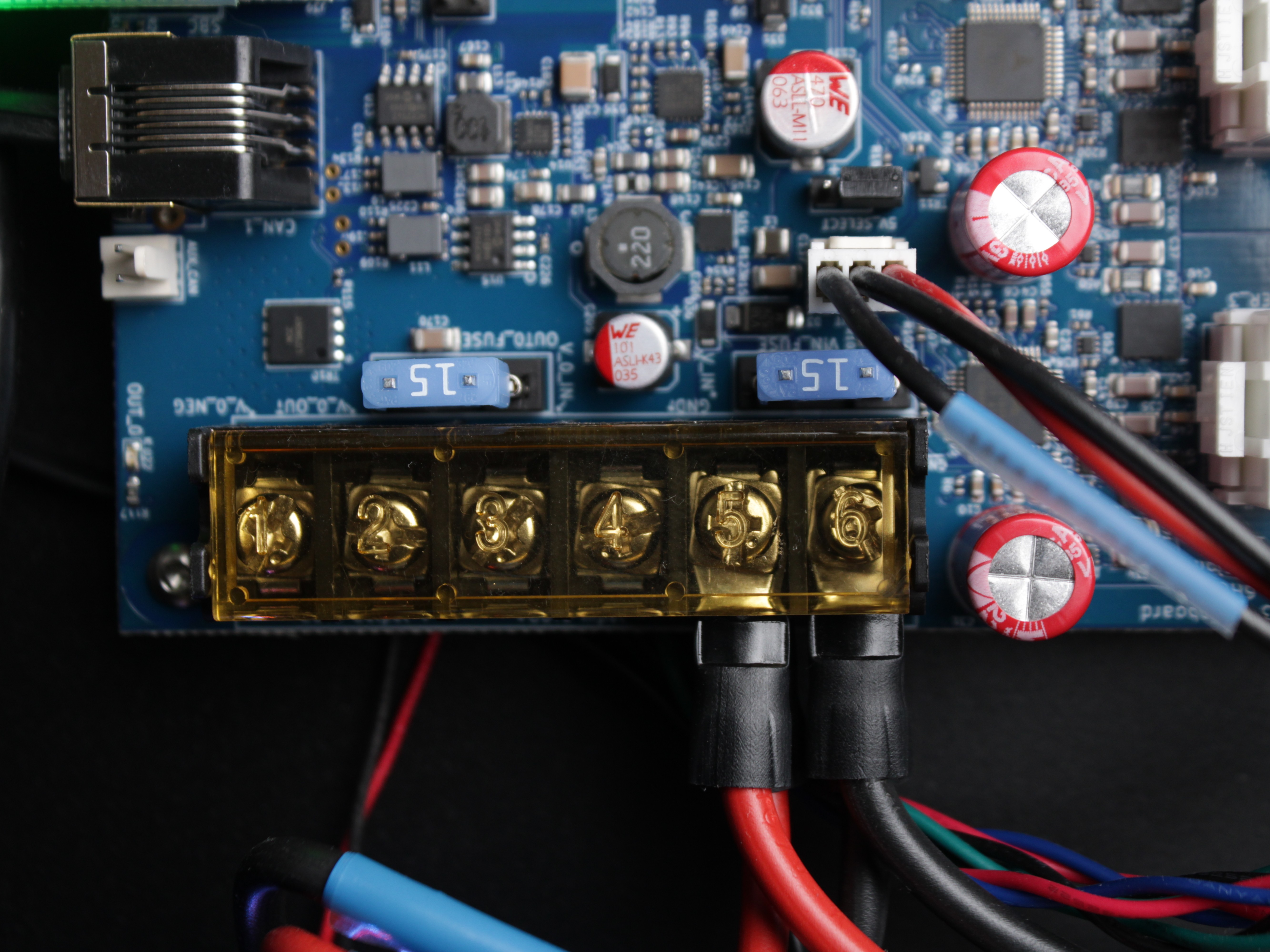
- Test each fuse with a multimeter set to continuity mode. Place one probe on each end of the fuse:
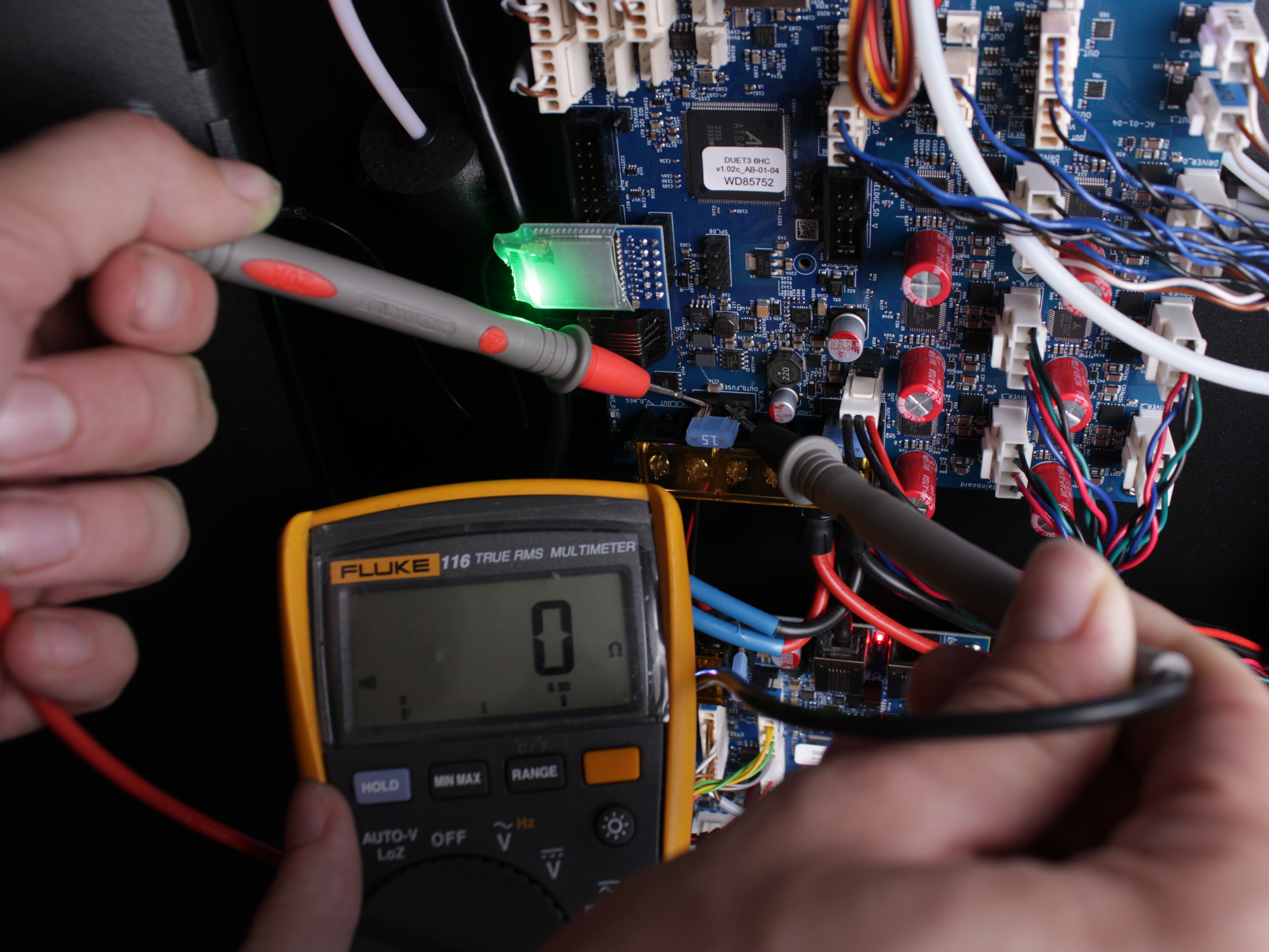
- Continuous beep - fuse is good.
- No beep (silence) - fuse is blown.
- Alternative visual check: remove the fuse with needle-nose pliers.
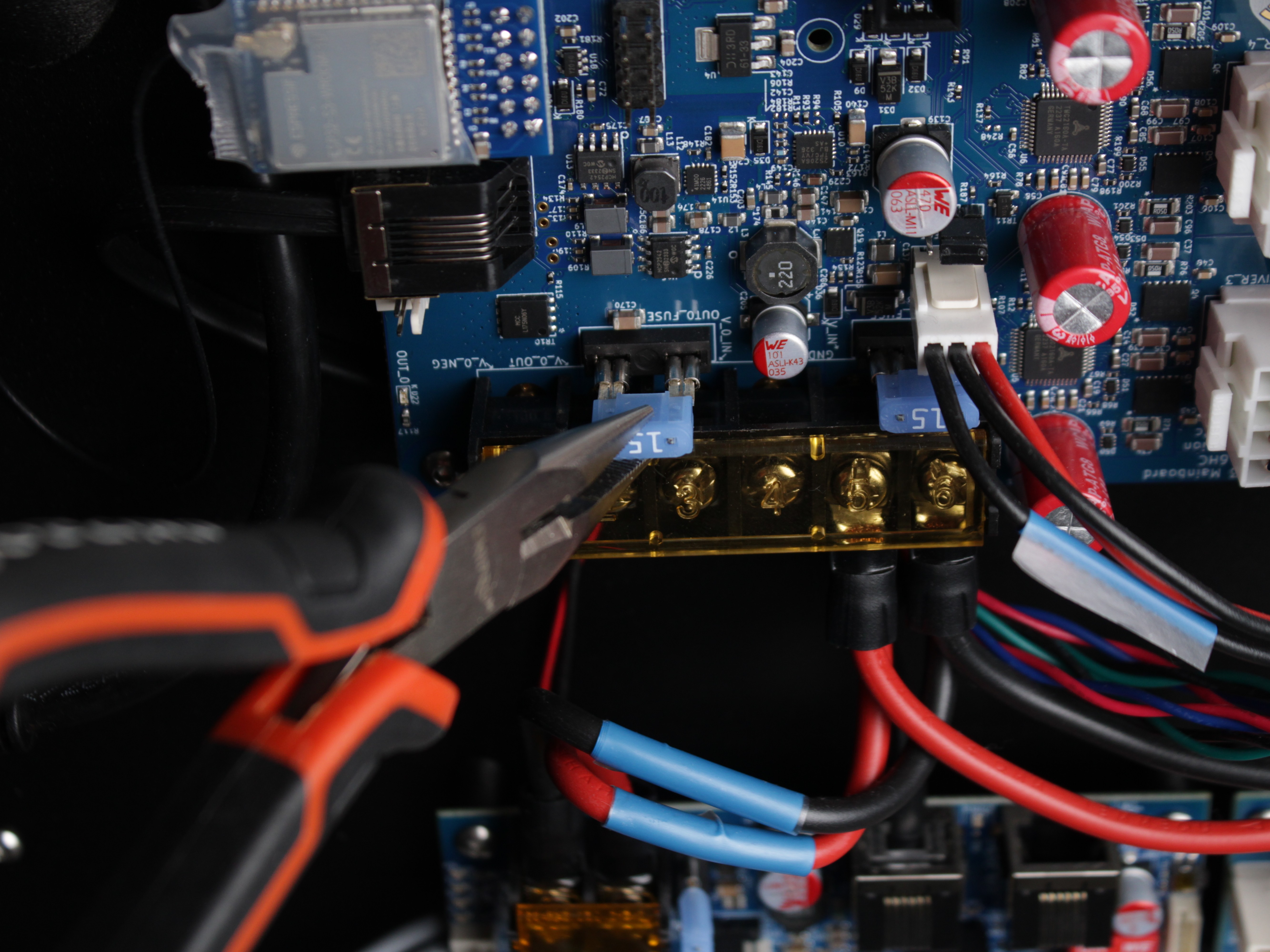
- Inspect the wire element inside the fuse. A break or dark discoloration means the fuse has blown.
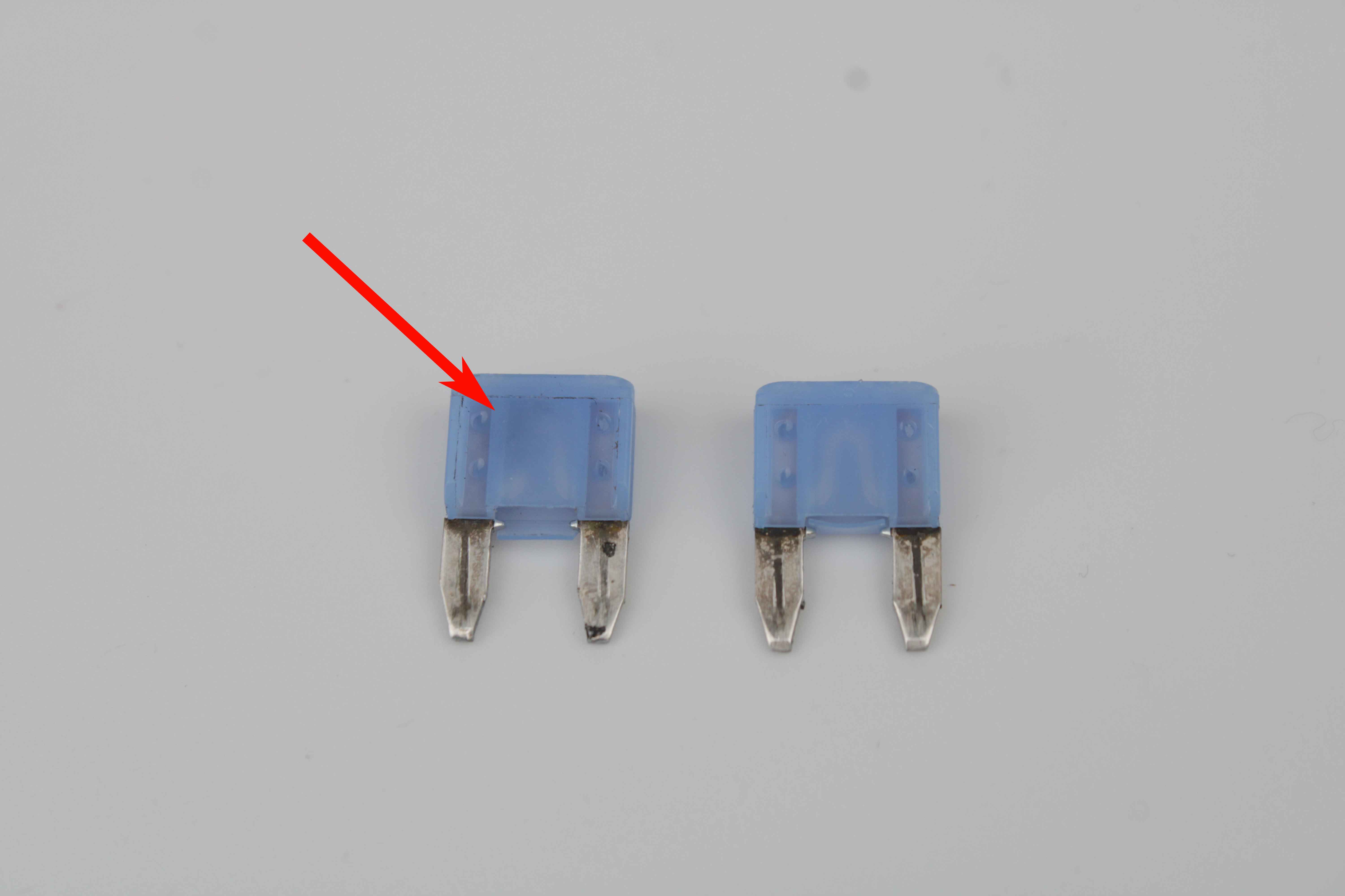
- Replace any blown fuse with an identical 15A fuse.
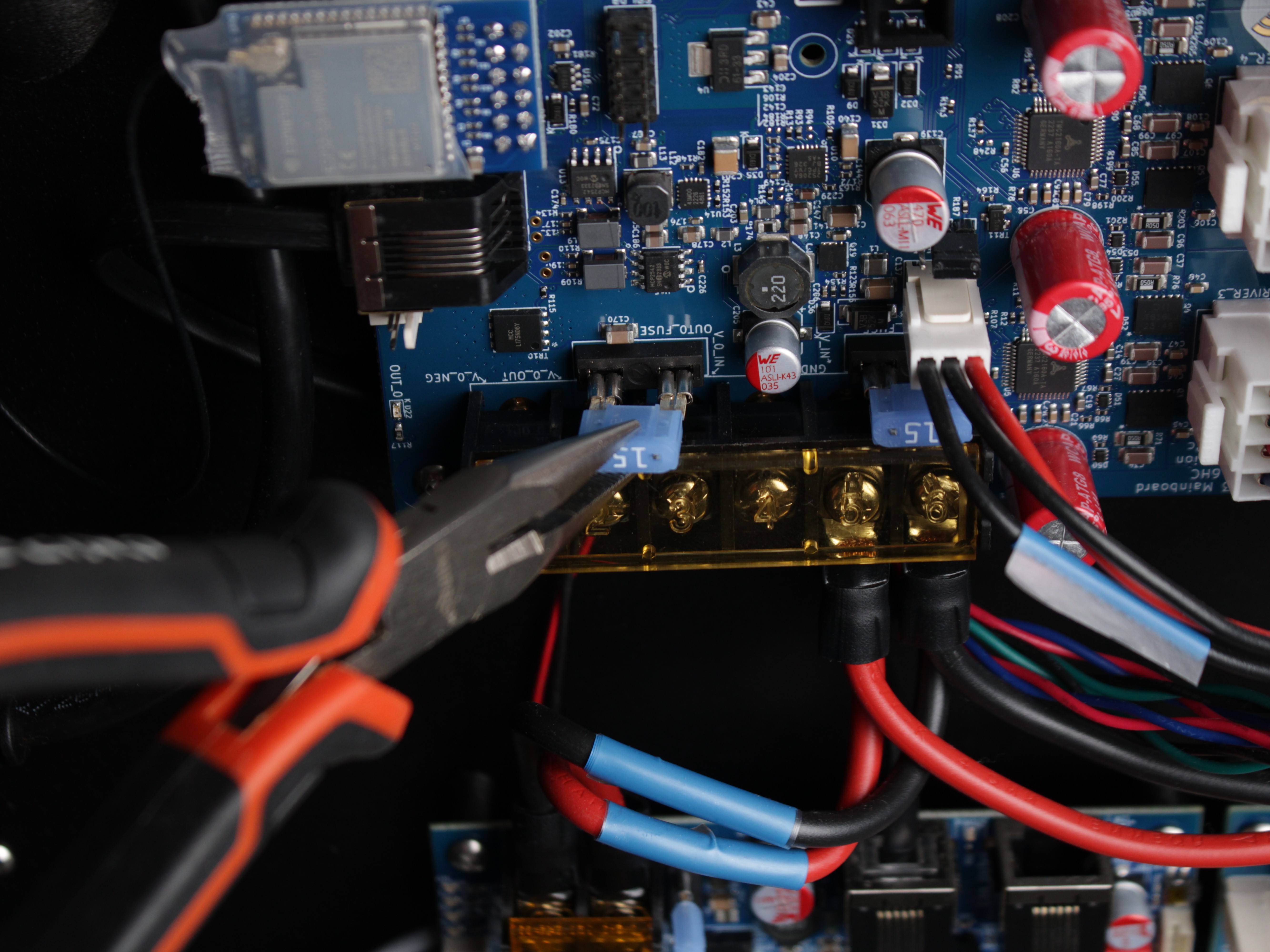
Fuse rating must stay 15A
Never install a fuse above 15 A. Overrating removes protection and can damage the board or create a fire hazard.
- Reconnect power and turn on the printer.
- If the printer powers on and axes respond - the issue is resolved. Before resuming printing, fix the original cause of the overload (e.g., seized motors). If you cannot identify the cause, contact technical support.
- If the printer still does not respond after replacing the fuse, the firmware on the SD card is the likely cause - see below.
Still No Signs of Life?
If you have verified both power-supply LEDs, both board LED sets, and the mainboard fuses, but the printer still will not boot - the STATUS LED is dim, off, or flashing 3× - the micro-SD card holding the firmware is most likely corrupted.
Continue with the SD Card & Firmware Recovery guide to reformat the card, install a clean firmware image, recalibrate, and (if needed) reflash the expansion board.
FAQ
Troubleshooting
Support
If you could not find an answer here, reach out to our support team.