SD Card & Firmware Recovery
22 IDEX V4 will not boot? Reformat the micro-SD card to FAT32, install a clean firmware image, then recalibrate and reflash the expansion board with M997 B1.
This guide covers reinstalling a clean firmware image on the Vision Miner 22 IDEX V4 when the controller will not boot because the micro-SD card is corrupted or the firmware is missing. It is the continuation of the Unresponsive Printer guide – use it once you have confirmed that power and fuses are fine but the board still does not boot (STATUS LED dim, off, or flashing 3×).
It walks through formatting the micro-SD card, copying a clean firmware image, the first boot, recalibration, and – if needed – reflashing the expansion board.
Before you begin - safety and risk
Read the Safety - Before You Begin article to understand the hazards involved in working on the Vision Miner 22IDEX V4 - including electrical, thermal, mechanical, and chemical risks. Mains voltage is present inside the electronics bay. All procedures in this wiki are provided as recommendations only. By choosing to follow any procedure, you do so at your own risk.
Unplug, wait, and discharge static
Turn off the printer, unplug mains, and wait at least 60 seconds before touching the mainboard. Use an anti-static wrist strap or touch grounded metal before handling boards.
Tools and Materials
- Micro-SD card reader
- A computer (Windows or macOS)
- Anti-static wrist strap (recommended)
1. Recovering a Corrupted SD Card
If fuses are intact and all board LEDs look correct, but the printer does not boot (STATUS LED is dim, off, or flashing 3×), the micro-SD card holding the firmware and configuration may be corrupted.
- Turn off the printer and unplug it from the power outlet.
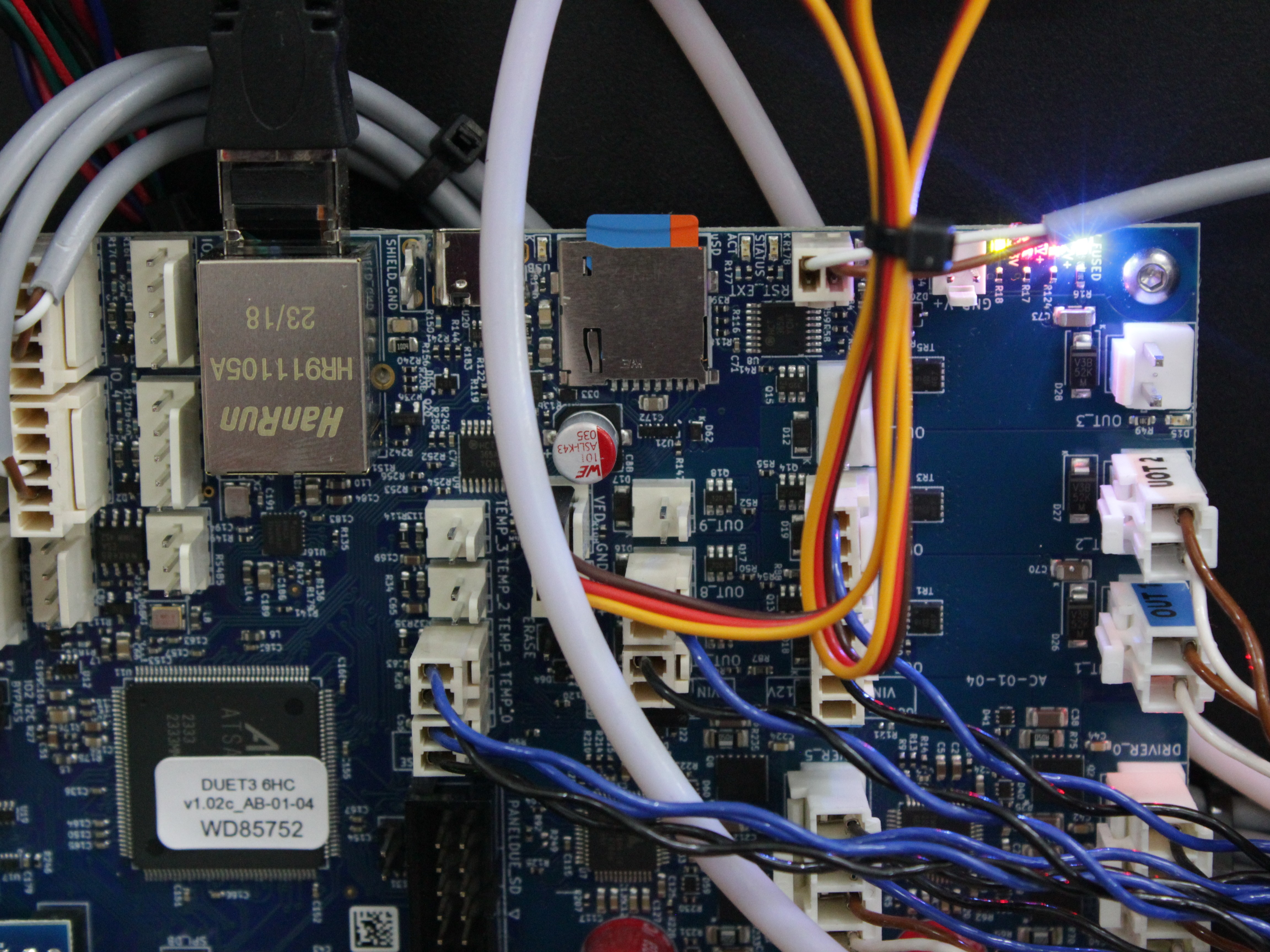
- Locate and remove the micro-SD card from the mainboard.
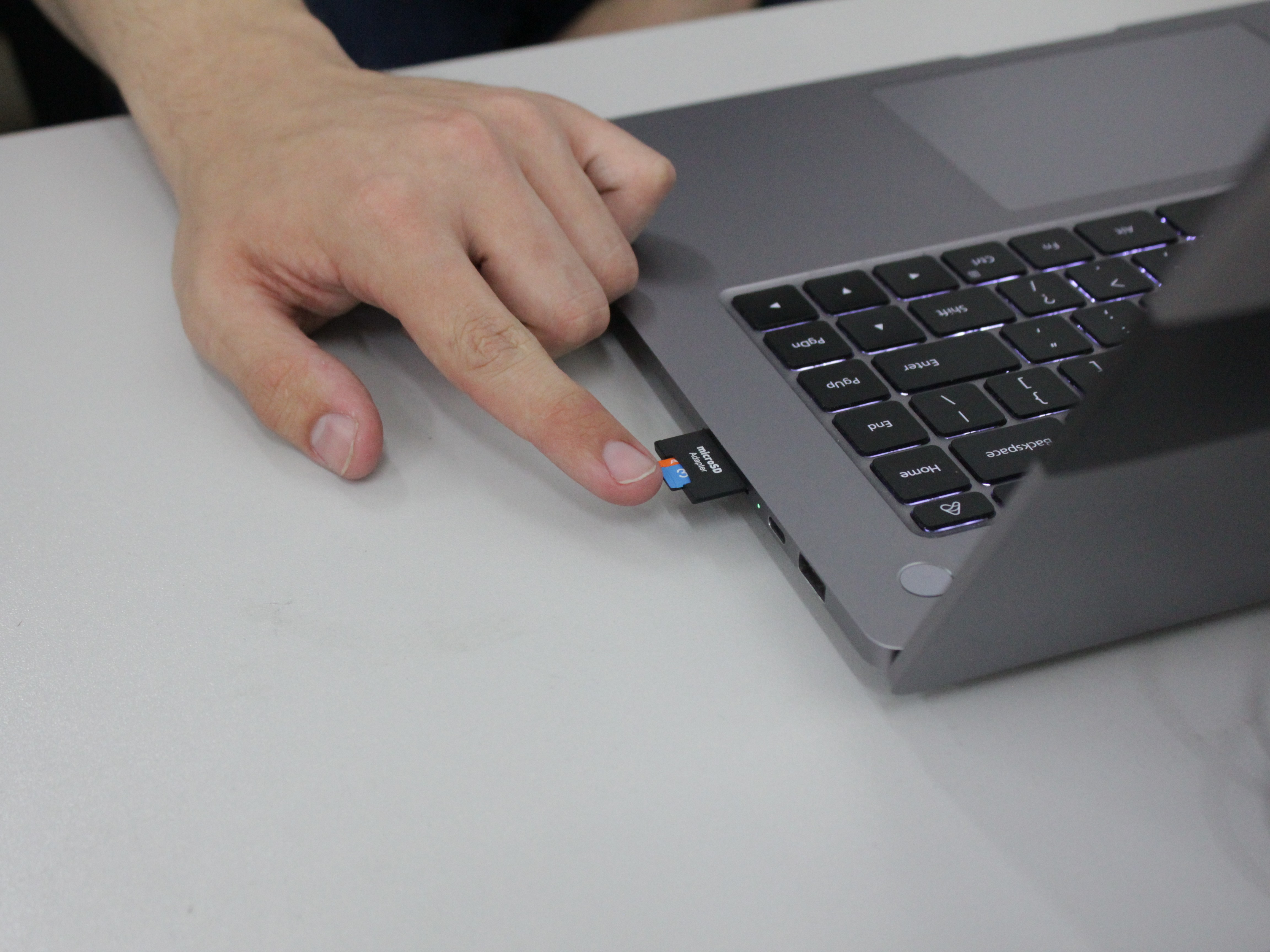
- Insert the card into a computer using a micro-SD card reader.
- Format the SD card using your preferred method. You must format the card as FAT32 - this is mandatory for the printer firmware to function correctly. Use your OS formatting tool (Disk Management on Windows, Disk Utility on macOS).
FAT32 format is required
The SD card must be formatted as FAT32. Other file systems (exFAT, NTFS) will not work with the Duet mainboard. If your card is larger than 32GB, use a third-party tool like Rufus or FAT32 Format to force FAT32 formatting.
2. Downloading and Installing Firmware
-
Download the firmware package for your printer version. Each package contains the complete SD card folder structure. On the V4, always use the latest version – the previous one is for rollback only, if support asked for it. For V3 machines, pick the package that matches when your printer was manufactured.
Version Filename 22IDEX V4 (latest) 22IDEX-V4-4.1.7-clean.zip 22IDEX V4 (4.0, previous) 22IDEX-V4-V4.0-clean.zip 22IDEX V3 (after Nov 2024) V3_New_clean.zip 22IDEX V3 (before Nov 2024) V3_Old_clean.zip Make sure you download the archive that matches your printer. If you install firmware from the wrong archive, the printer will not work correctly. If you have any doubts about which archive is right for your machine, contact our support team before flashing.
-
Extract the downloaded ZIP file.
-
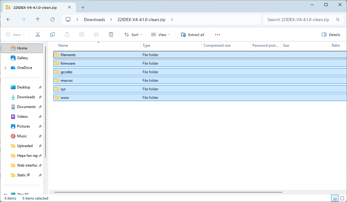
Copy all extracted folders from the archive to the root of the freshly formatted SD card. Everything must sit at the root of the card - not nested inside an extra folder.
3. Reinserting the SD Card and First Boot
- Safely eject the SD card from the computer.
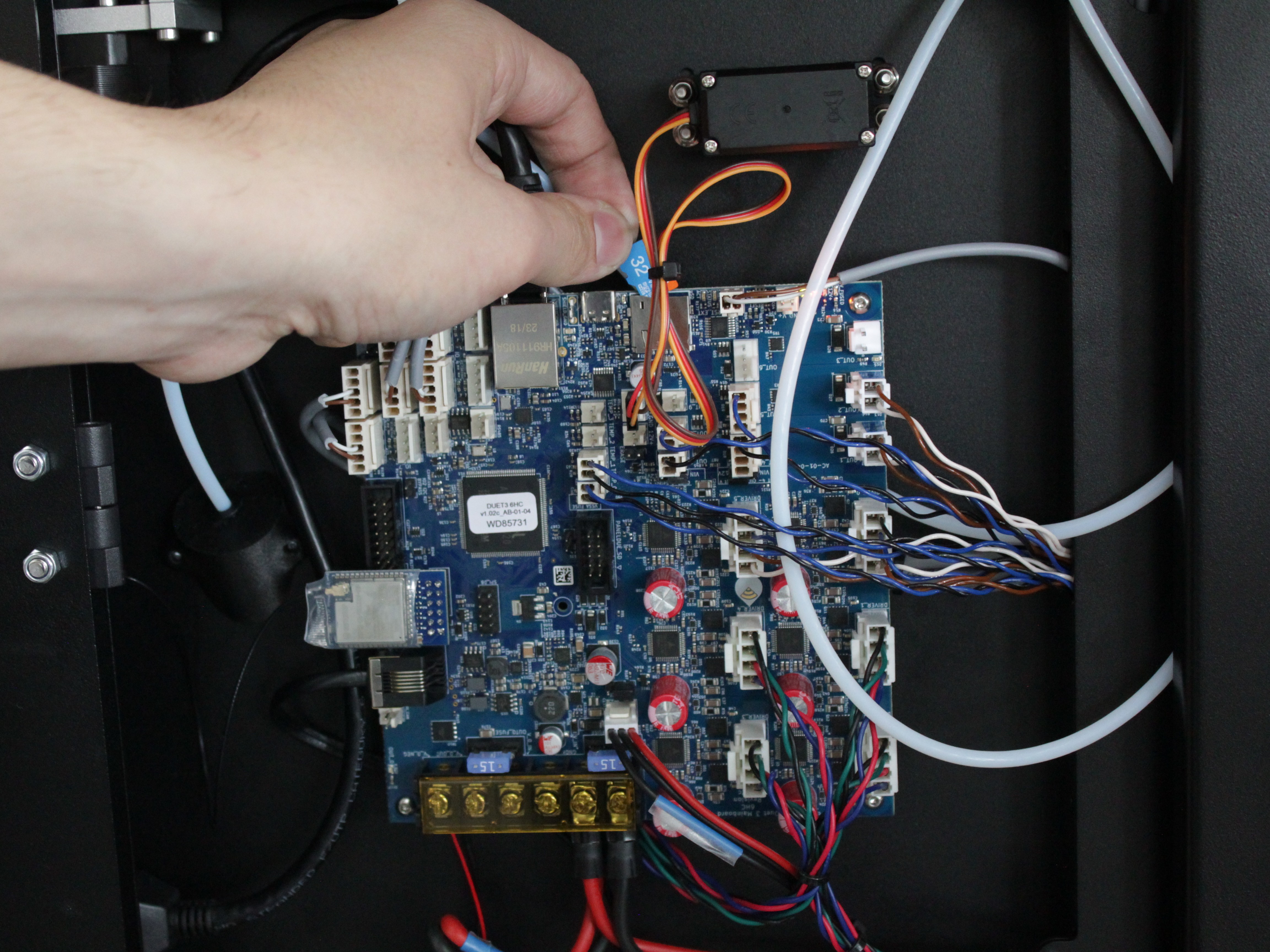
- Insert the SD card into the mainboard's micro-SD slot.
- Plug in and power on the printer.
- With a fresh firmware image, the printer starts in factory configuration - no network settings are saved. It boots into Wi-Fi Access Point mode, broadcasting an SSID named
22 IDEX. - To access the printer, connect to the
22 IDEXWi-Fi network from your computer or phone. Use the password1234567890if the network is not already saved on your device. Once connected, open a browser and navigate to the Web Interface. If the interface loads, the firmware is running and the SD card recovery was successful.
Expansion board errors? Fix them before calibrating
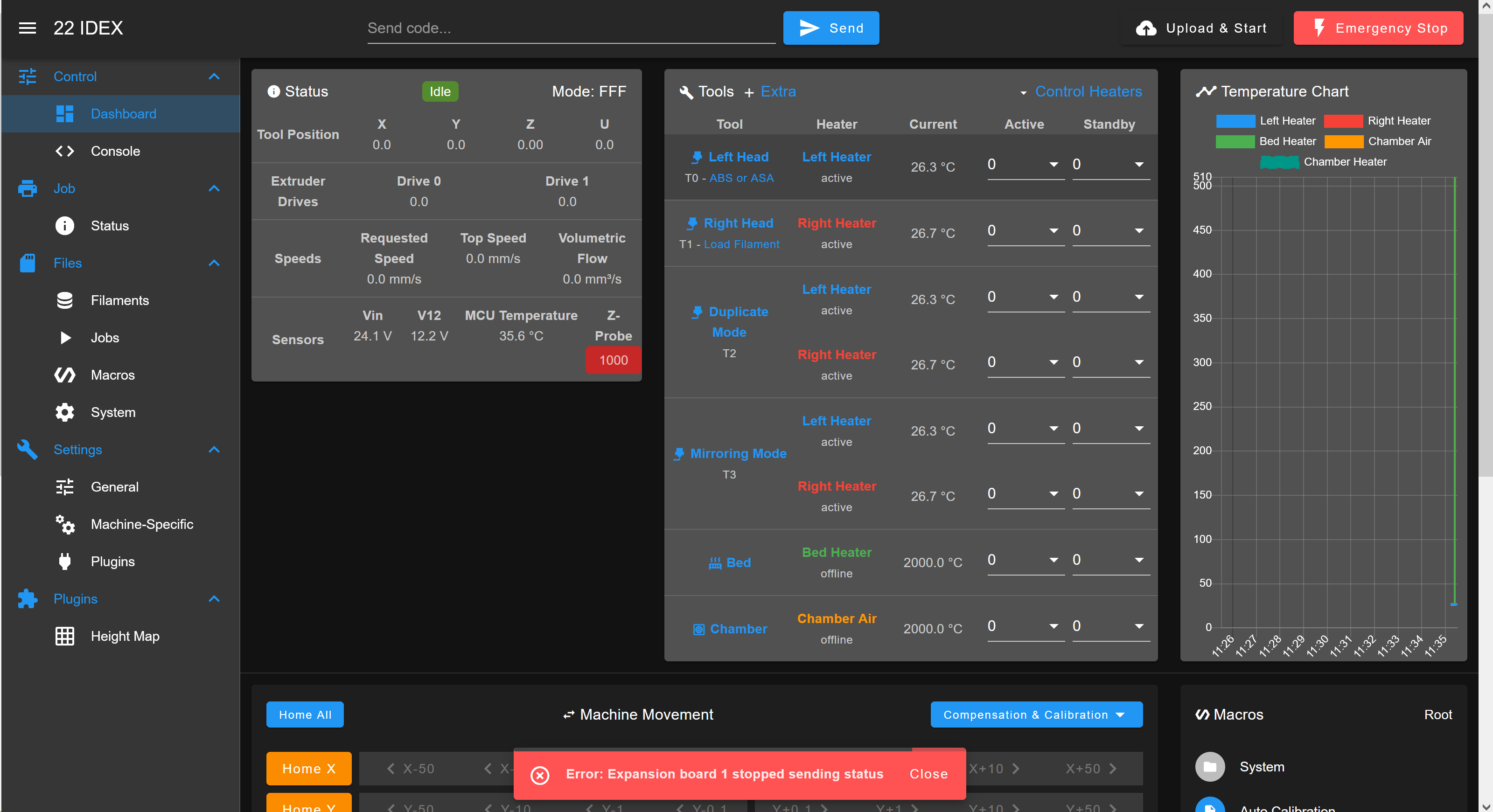
If the Web Interface loads but the printer still does not work correctly - Tool 1 or the bed does not respond, LEDs do not light, or you see errors related to the expansion board (Tool 1) - complete the Fixing Expansion Board Firmware Issues section below first, then return here to finish calibration.
4. Final Calibration
A fresh firmware install resets the network settings and all calibration data, so the printer must be reconnected and recalibrated before it can print. Run these procedures in order.
- Reconnect the printer to your network. Recovery leaves the printer in its default Wi-Fi Access Point mode. Set up your normal connection so you can reach it during regular use – see WiFi Setup or Ethernet Connection.
- Calibrate the Z-Probe. A fresh firmware install clears the saved probe pickup angle and position. Run the Z-Probe Calibration procedure first, because Auto-Calibration relies on a working probe.
- Run Auto-Calibration. Run the full Auto-Calibration procedure to restore tool height, Z-offset, and tool offsets.
- Verify bed leveling (3-square test). A fresh install also resets the mesh compensation to zero. Run the Bed Leveling Calibration 3-square test to confirm the first layer is even from the left to the right side of the bed, and tune it if needed.
- Your printer is now calibrated and ready to print.
5. Fixing Expansion Board Firmware Issues
Use this section if, after recovery, the Web Interface loads but Tool 1 (the right tool, driven by the expansion board) misbehaves. Typical signs:
- Tool 1 temperature reads a nonsense value (for example around 2000 °C) or shows a sensor fault.
- Tool 1 or the expansion board is not detected at all.
- The event log shows errors mentioning the expansion board.
To confirm, open the Machine-Specific tab in the Web Interface and check the expansion board firmware version. If it is missing or incorrect, the expansion board firmware failed to load during recovery and needs reflashing.
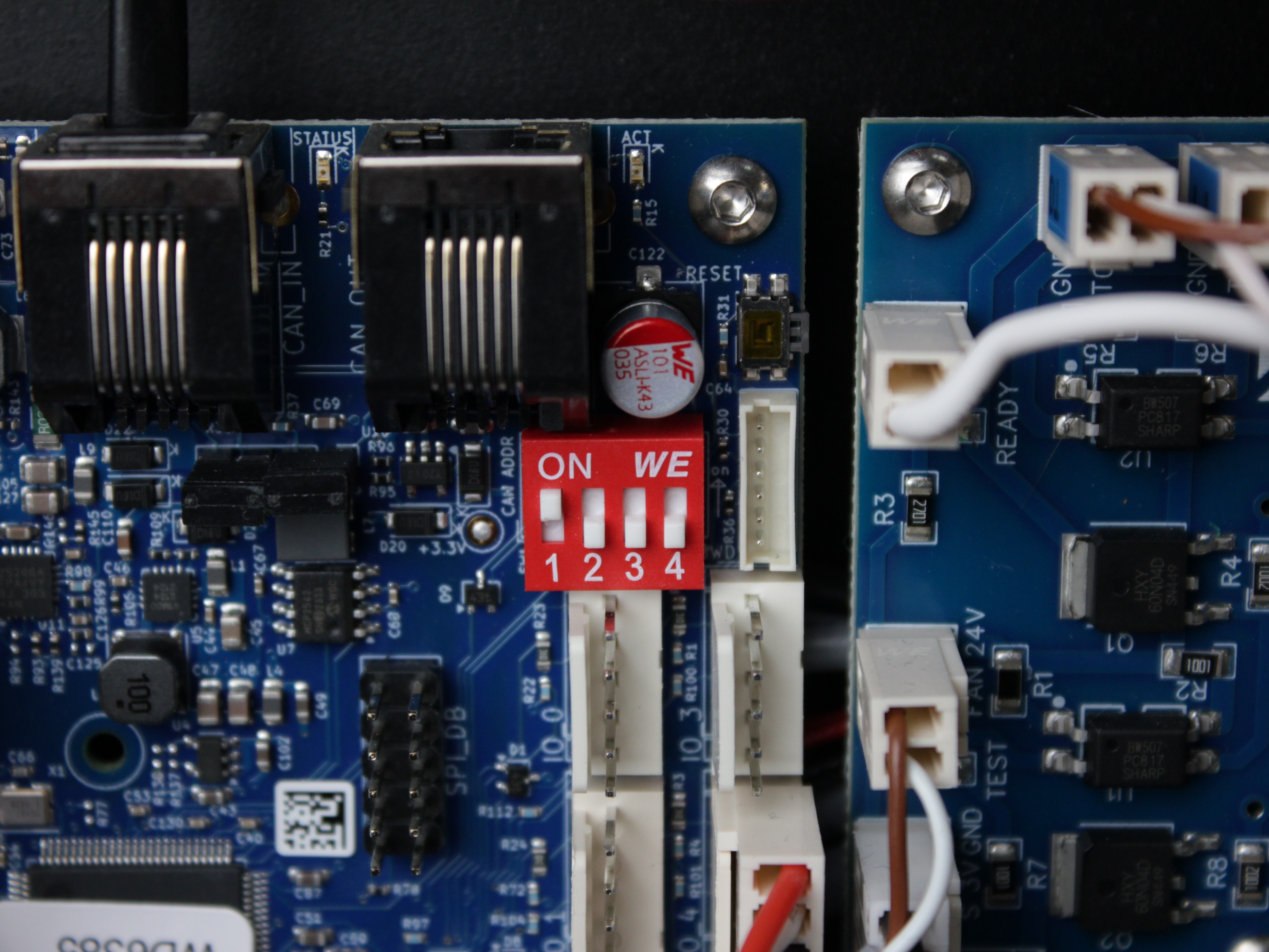
- Verify the clock jumper position. On the expansion board, check that the clock selection jumper is in the correct position. The jumper must be set as shown in the photo below - incorrect jumper position prevents the expansion board from functioning and is required before flashing new firmware onto the expansion board.
- Open the Console tab in the Web Interface.
- Send the following command to flash the expansion board firmware:
M997 B1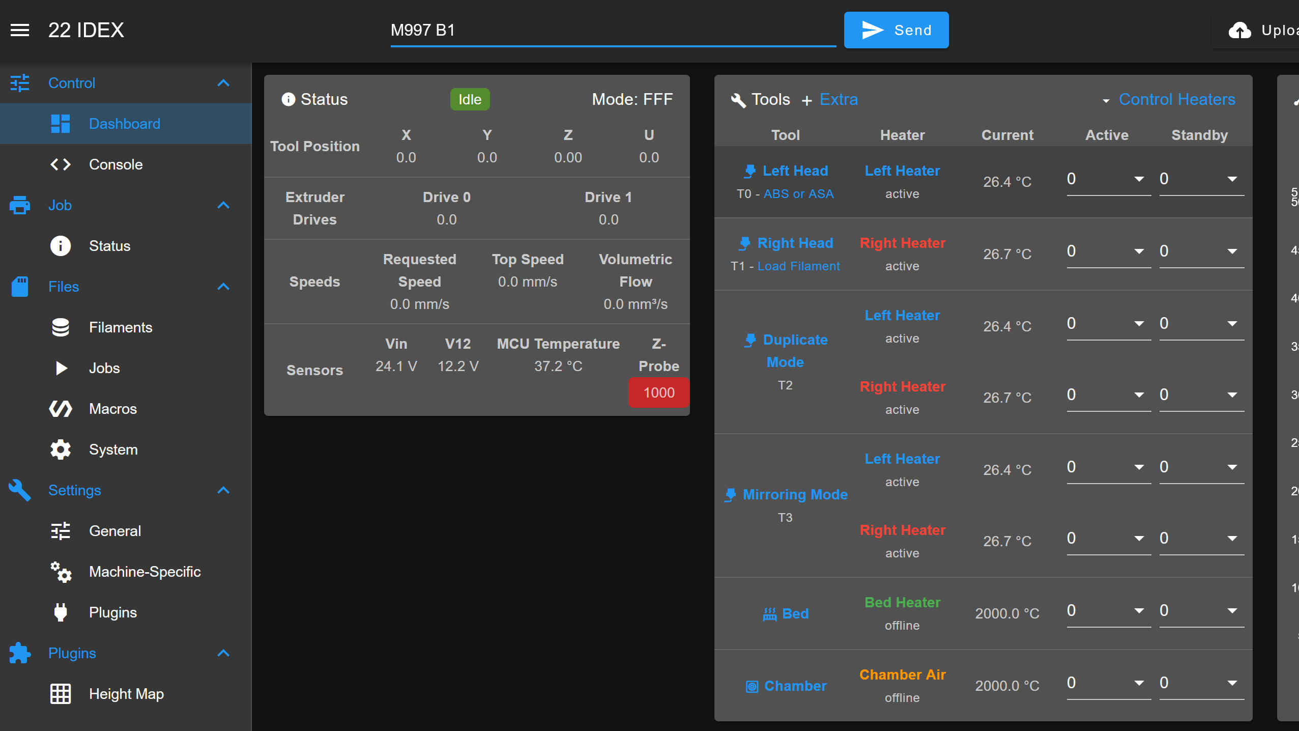
- Wait for the expansion board to complete the firmware update.
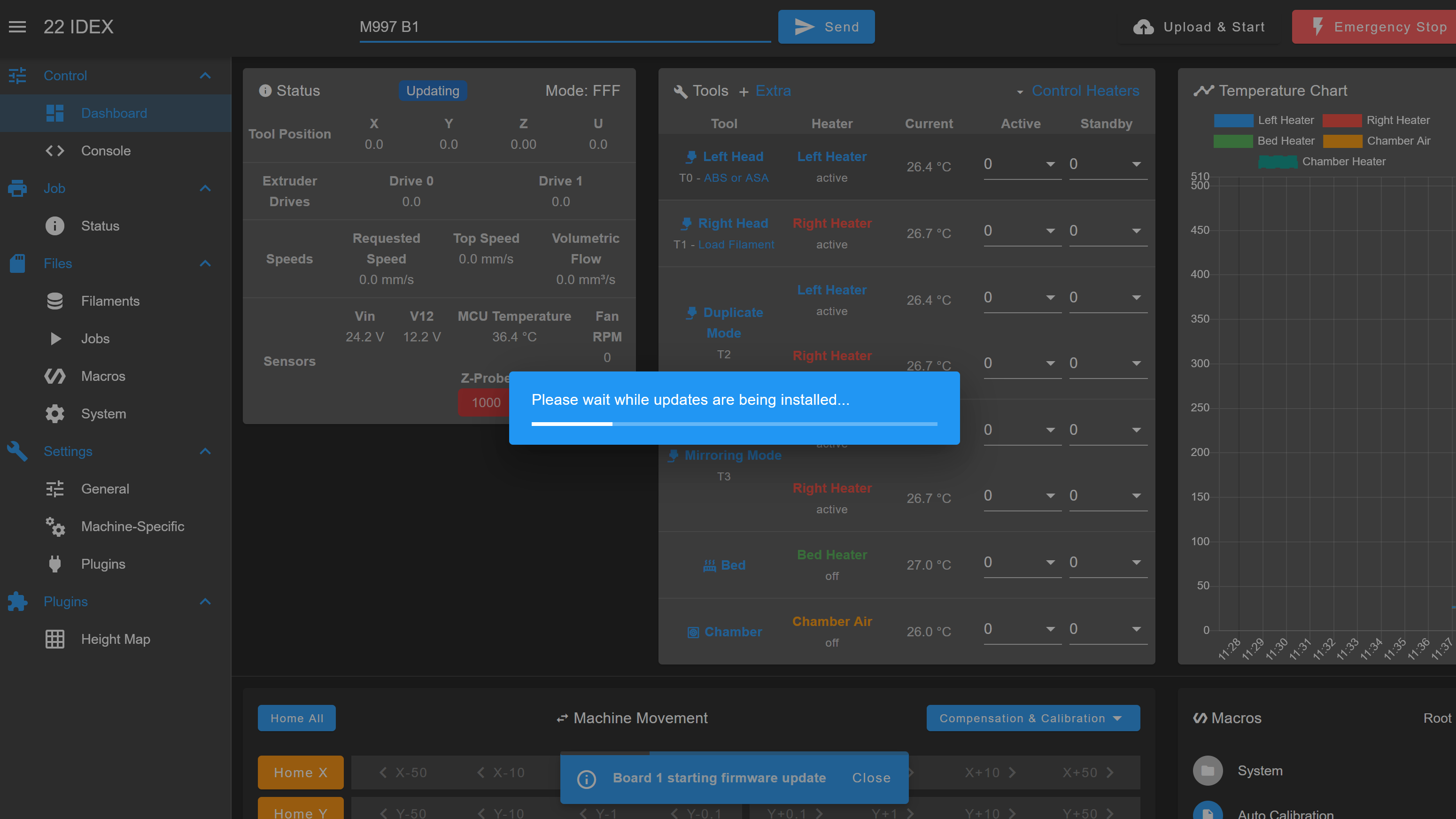
- After the update completes, the printer does not restart on its own. Turn it off using the power button on the front of the printer, then return the button to its original position to turn it back on. Once the printer boots and the expansion board is working, return to Final Calibration and complete the calibration steps.
6. Optional: Updating Mainboard, Wi-Fi, and Screen Firmware
The clean firmware package includes the firmware binaries for every module. If a module is misbehaving after recovery, you can reflash it individually from the Console tab. These steps are optional - only run them if a specific module is not working.
| Command | Module updated |
|---|---|
M997 (or M997 S0) | Mainboard (Duet 3 MB 6HC) |
M997 S1 | Wi-Fi module |
M997 S4 | Touchscreen (PanelDue) |
M997 B1 | Expansion board (covered in Section 5) |
Never interrupt a firmware flash
Do not power off the printer or close the browser while an M997 update is running. Interrupting a flash can leave the module in an unbootable state that requires recovery with the BOSSA utility - contact Vision Miner support if this happens.
FAQ
Support
If you could not find an answer here, reach out to our support team.