First Layer Calibration
Fix first-layer squish with Z babystepping, level the bed left to right with the 3-square test, heat soak the machine when the corners print differently from the center, and balance both nozzles in Mirror or Duplicate mode.
Use this guide when the first layer shows wrong squish (too high or too low), when one side or one corner of the plate prints differently from the rest in Standard Mode, or when Mirror / Duplicate jobs need a stable first layer. This guide does not replace Auto Calibration - run that first so Z starts close to correct.
Before you begin - safety and risk
Read the Safety - Before You Begin article to understand the hazards involved in working on the Vision Miner 22IDEX V4 – including electrical, thermal, mechanical, and chemical risks. All procedures in this wiki are provided as recommendations only. By choosing to follow any procedure, you do so at your own risk.
Babystepping uses hot nozzles and motion
Adjust Z only through the Web Interface during a print. Stay clear of the toolheads – the machine can move without warning.
On this page
Work top to bottom, or jump straight to your situation:
- Read the first layer - tell too high, too low, and good apart, and narrow the cause down by where on the plate it happens.
- Z adjustment - babystep Z during the print.
- Save Z-offset - keep the tweak after the print.
- Left vs right height - fix a left-to-right tilt with the 3-square test and the RHS macros.
- Center vs corners: heat soaking - the middle is right but the far corners or edges are not.
- Mirror and Duplicate modes - stable first layer when both toolheads print at once (raft and per-nozzle flow split).
Printing in Mirror or Duplicate mode?
If both toolheads print at the same time, go straight to Mirror and Duplicate modes - that section covers the raft and the per-nozzle flow split you need.
Equipment and Software
- Vision Miner 22IDEX V4 with a build plate installed for real prints (remove the plate only when Auto Calibration requires bare aluminum - follow that guide).
- Computer on the same network as the printer - Web Interface in a browser.
- A small test job - wide skirt or brim, or a small cube - so you can judge layer 1 without a long print.
- Build plate cleaned and coated with NPA - always print on NPA, whatever the material (including PLA). See the NPA Application Guide.
- Slicer (e.g. PrusaSlicer family) - only if you use a raft for Mirror/Duplicate (see below).
1. Read the first layer
| Look | What you see |
|---|---|
| Too high | Visible gaps between lines, weak bond to the plate. |
| Too low | Ripples, ridges, or washboard squish. |
| Good | Lines touch and bond without crushing into a wavy surface. |
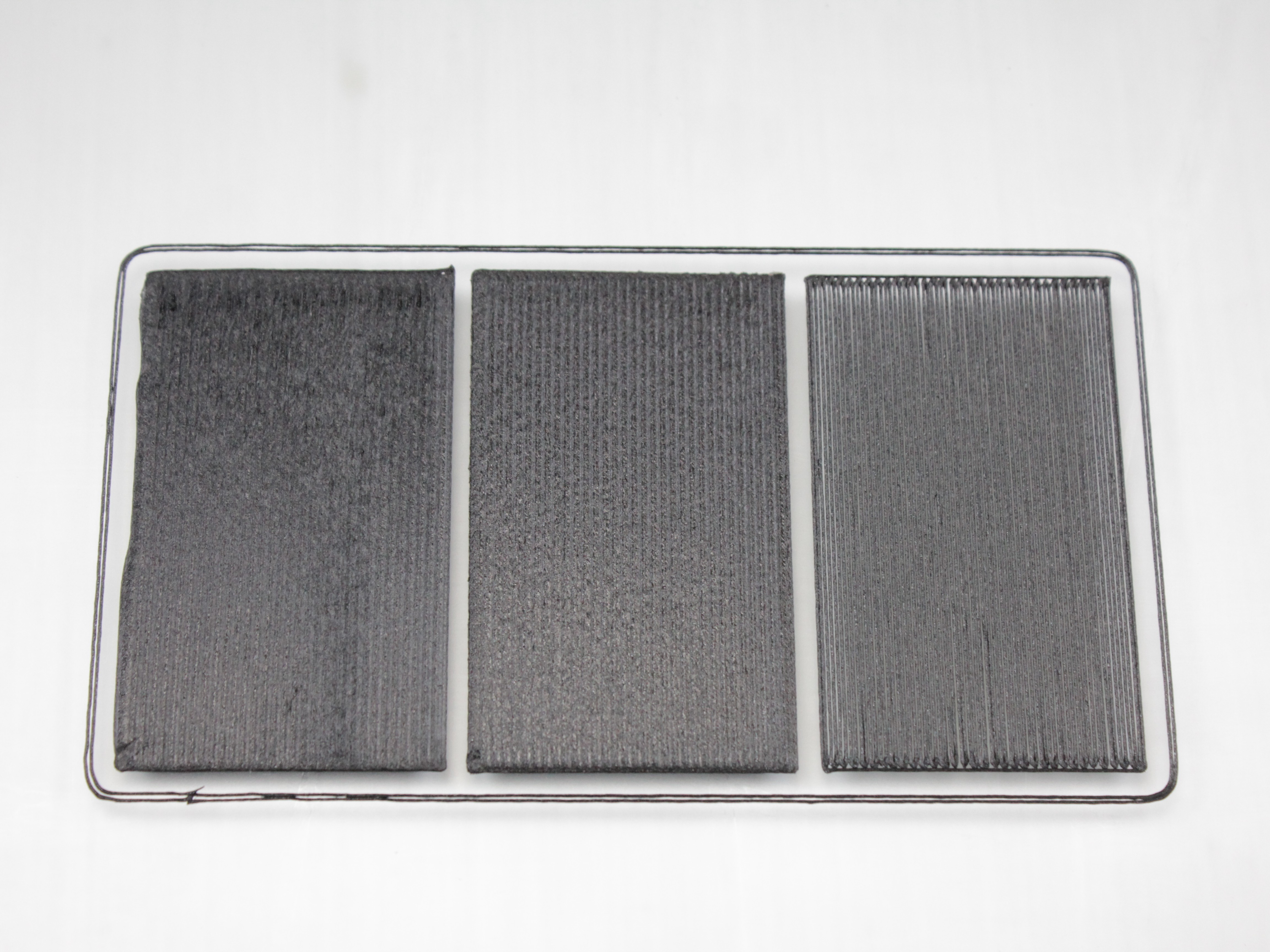
Where on the plate
Once you can tell too high from too low, look at where it happens. The pattern points to the cause, and each cause has its own fix - babystepping only solves the first row.
| Pattern | Likely cause | Go to |
|---|---|---|
| Same everywhere - the whole layer is too high or too low | Z-offset | 2. Z adjustment |
| One side (left or right) differs from the other; front and back look the same | Left-to-right tilt in mesh compensation | 4. Left vs right height |
| Center is right, the far corners or edges are not (often front and back) | Machine was not heat-soaked when the plate was measured | 5. Center vs corners: heat soaking |
| Changes from print to print with nothing touched | Z-probe repeatability | FAQ |
| Only the corners of each line or square have gaps; the rest is fine | Pressure advance too high for the nozzle | FAQ |
Photograph the whole plate
Before you adjust anything, take one photo of the entire plate with the test print still on it, then close-ups of each area. Left-right tilt, corner drop and Z-offset look alike in a close-up and are easy to tell apart in the overview. Support will ask for the same set.
2. Z adjustment
- Start your test print. Use enough skirt or brim to watch layer 1 for a minute or two.
- Judge the lines using the table above.
Hot nozzle during babystepping
Do not touch the nozzle or heater block. The machine may move without warning during adjustment.
- Open the Web Interface. Go to the Status tab.
- Use Z babystepping:
- Nozzle too close to the plate - tap
+0.02 mm(moves Z to give more clearance). - Nozzle too far - tap
-0.02 mm.
- Nozzle too close to the plate - tap
- Change only during the first layer. Leave the value for the rest of the print so the job stays consistent.
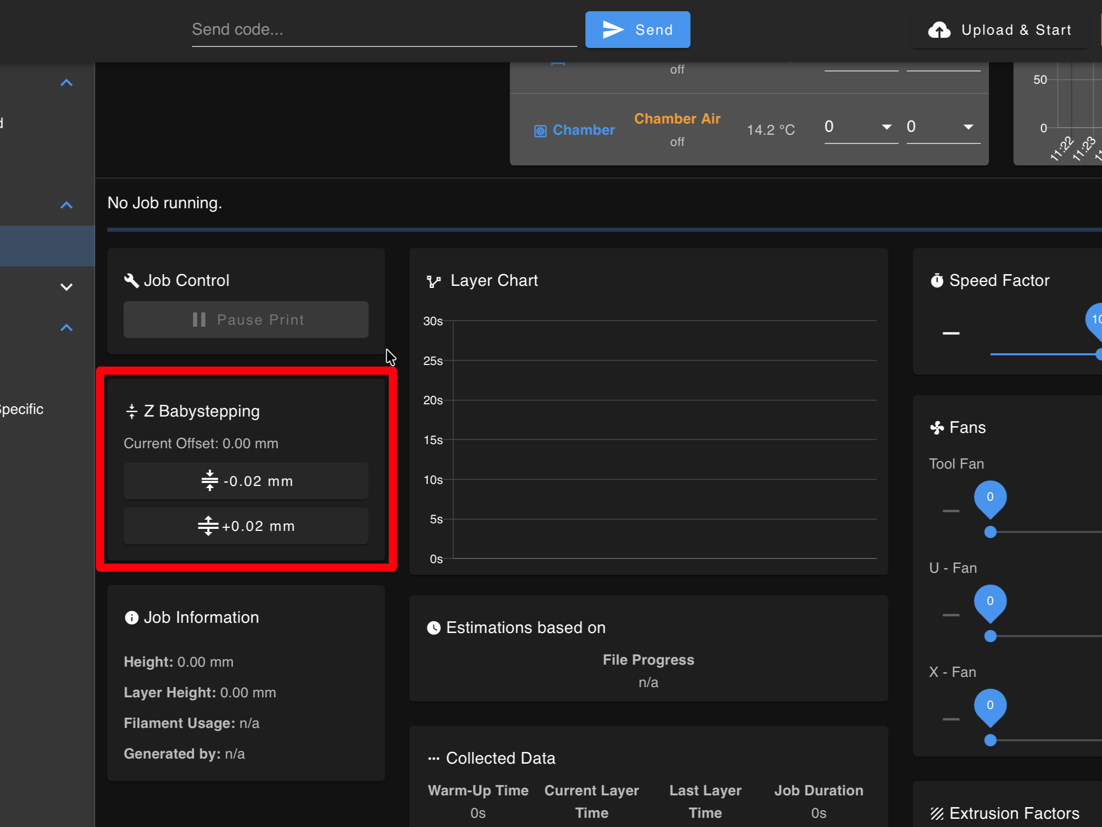
The red highlight shows the location of the Z babystepping controls.
3. Save Z-offset
After the print:
- If you changed Z during the print, the printer shows a reminder after the job ends: "Adjustment of ... mm was detected. It is recommended to save this Z-Offset adjustment." This popup is only a reminder - clicking OK does not save anything.
- Run
Dashboard > Macros > Save Current Z-Offsetto actually save the adjustment. - If you skip the macro, the tweak is lost on the next boot or job.
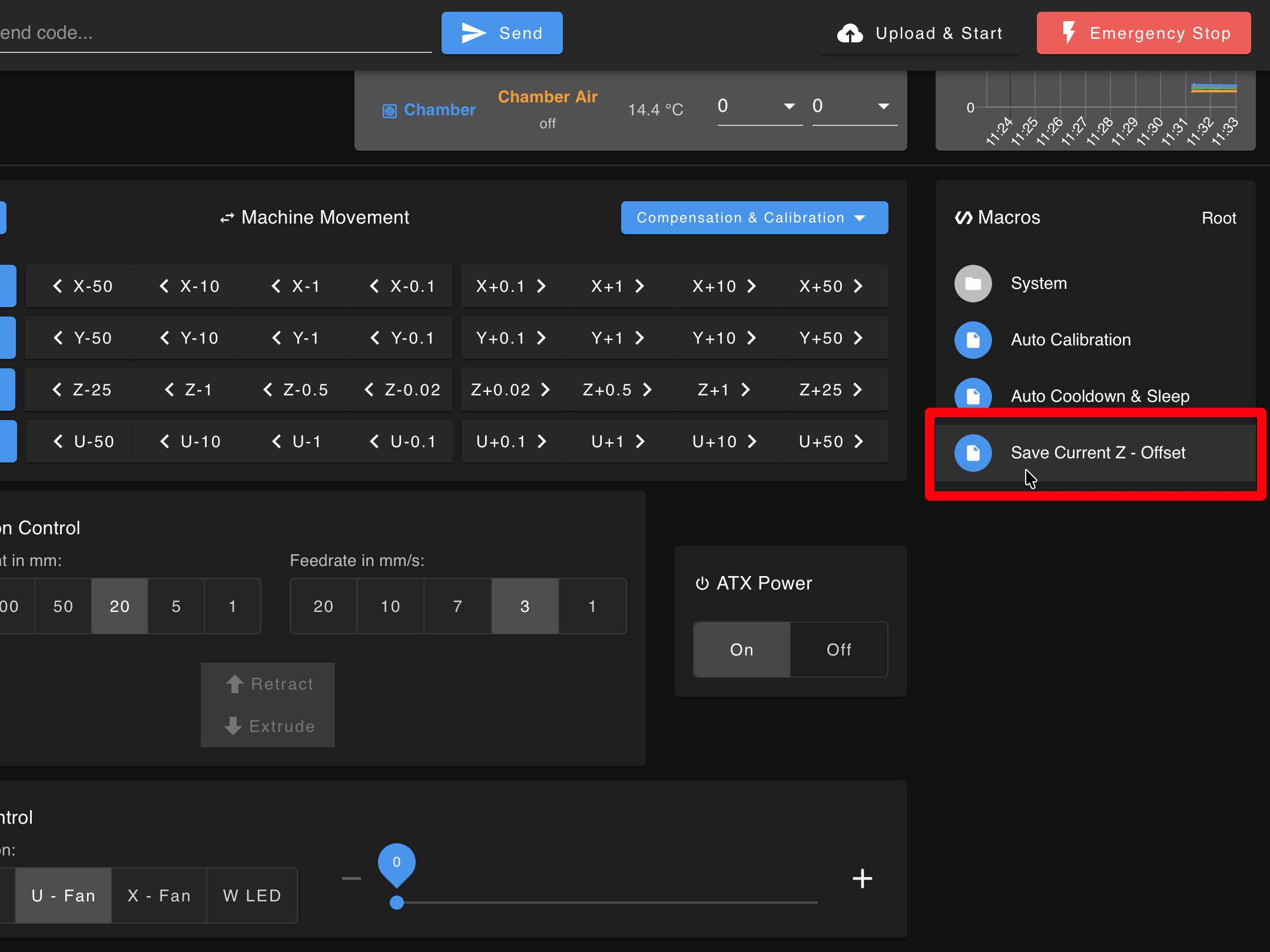
The red highlight shows the Save Current Z-Offset macro location in the Dashboard > Macros menu.
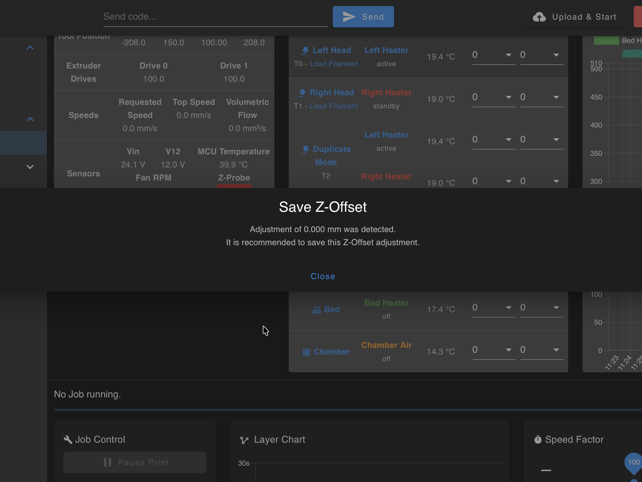
After clicking the macro, a popup appears to confirm the save action.
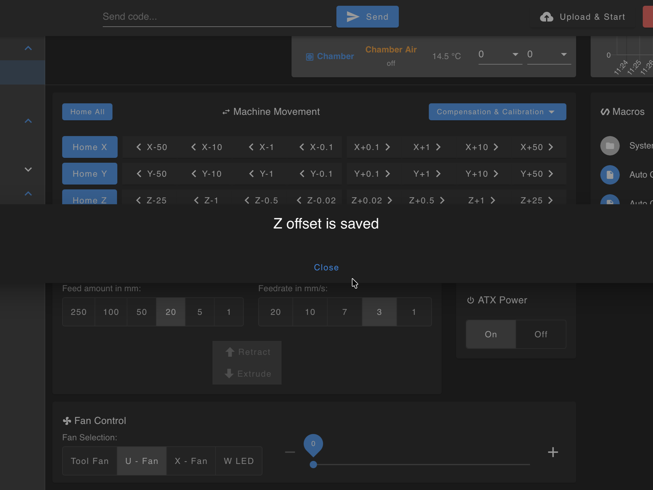
The confirmation message verifies that the Z-offset has been saved successfully.
4. Left vs right height
If the left side of the plate prints higher or lower than the right, the left-to-right mesh compensation is tilted. Two things will not fix it:
- Babystepping moves the whole plate up or down. It cannot fix one side.
- Auto Calibration. V4 machines ship in Manual mesh mode, and in that mode Auto Calibration leaves the left-to-right value alone. Running it again changes nothing on the sides.
The fix is a one-time manual adjustment with the 3-square test and the RHS Up / RHS Down macros. It is saved on the printer and survives reboots, homing and Auto Calibration. The short version:
- Print
Mesh Bed Test.gcodefrom Jobs > Slicer > Tests. Babystep the center square until it looks right and save the Z-offset (steps 2 and 3 above). - Compare the left and right squares to the center.
- Go to Macros > System > Calibration > Mesh Calibration and press one macro, once:
- Right square too far (gaps), or left square too close (buildup) → ↓_↑ RHS Up.
- Right square too close (buildup), or left square too far (gaps) → ↑_↓ RHS Down.
Each press moves the right-hand side by 0.04 mm and the printer confirms the new value in the Console (for example
RHS of Build Plate adjusted down to -0.16mm and saved).
- Print the test again and compare. Repeat until all three squares match.
RHS Up / RHS Down are not live
The macros change a stored value that the printer applies at the start of the next print. Pressing them during a running print shows no change on the plate. Do not keep pressing - a stack of presses applied to the next print will throw the side off by far more than you wanted. Adjust between prints, then re-print the test.
Full steps with photos of each case: Bed Leveling Calibration.
Large parts: the 9-square test
In most cases, the 3-square test and the adjustments above are enough to set the left-to-right compensation. If the center looks right but the front or back edges of a large part still print unevenly, work through 5. Center vs corners: heat soaking first.
If the problem remains after those checks, contact support with a photo of the full plate and close-ups of the affected areas. Support can provide the 9 Mesh Bed Test.3mf file if further diagnosis is needed. This is an optional follow-up test, not a required calibration step.
The test has three rows of three squares and checks more of the plate than the standard 3-square test. If support asks you to run it, slice it with your filament profile and read it in two passes:
- Compare left to right within each row. A consistent difference across all three rows is a left-to-right tilt - fix it with the RHS macros above.
- Compare front to back within each column. If the center row is right and the front or back rows are off - especially the corners - that is not a mesh tilt. Go to 5. Center vs corners: heat soaking.
5. Center vs corners: heat soaking
How it looks: the middle of the part or the center squares are right, but the far corners or the edges of the plate are too low or too high - often the back corners squashed and the front ones lifted, or the other way round. The same job printed later in the day, on a machine that has been hot for a while, comes out better.
Why it happens: the printer probes the plate and sets Z at the start of every job. As the build plate, the frame and the motion system come up to temperature they expand, and they do not expand evenly - the plate bows slightly one way, the gantry the other. The center barely moves; the edges and corners move the most. A plate probed on a cold or half-warm machine is therefore wrong at the corners by the time the first layer goes down. The effect grows with bed and chamber temperature (PC, nylons, PEI, PEEK) and with parts that reach the edges of the plate.
What to do:
- Let the printer heat soak before it probes. Firmware 4.1.x does this on its own: it heats the bed and chamber, waits for the chamber to reach target, holds a heat soak of up to 5 minutes (the colder the chamber started, the longer the soak; none if it was already near target), and only then homes, probes the plate and starts the print. The heat soak is skipped whenever the chamber wait is skipped, so for these jobs:
- Answer Wait if the printer asks "Skip chamber heating wait?" at the start, and keep Macros > System > Settings > Printing > Wait for Chamber Temp on Wait.
- Do not press Start Now on the Chamber Heating Rate Warning or Chamber Wait Timeout dialogs. If those appear, the chamber is not heating properly - see point 2.
- A job with no chamber target gets no heat soak at all. For large flat parts, set a chamber temperature even for materials that do not strictly need one.
- Need a longer soak? The firmware's 5 minutes cannot be extended, but you can soak before the job: set the bed and chamber to the printing temperatures in the Web Interface, wait 15-20 minutes after both reach target, then start the print. The machine is then already stable when it probes the plate.
- Check that the chamber really reaches its target. If it stalls well below (say 75 °C with a target of 90 °C), or the reading says "at target" while the nozzles report a much lower temperature, the plate is not at the temperature the mesh is probed at, and the corners will be off no matter how long you wait. See the FAQ below.
- Still off after a full heat soak, or a large print keeps failing at the corners - check the plate itself. Put the glass plate in, let the machine heat soak with the bed and chamber at your printing temperatures, then run the same plate probe the printer runs before a print: in the Console, send
M98 P"0:/sys/mesh.g", and open the Height Map in the Web Interface. A flat, level map means the plate is fine and the cause is elsewhere. A clear bow or one high corner on glass points to the plate seating or the frame - contact support with the height map and the overview photo of the plate.
Heat soak is part of every print, not just calibration
The Print Checklist asks for a 15-minute heat soak before any high-temperature job for the same reason. The firmware's pre-print wait covers the minimum; for large flat parts in PC or nylon, a longer soak with the chamber at target does no harm.
6. Mirror and Duplicate modes
Large mirror/duplicate areas amplify small mechanical and plate errors. Layer heights are tens to hundreds of microns - small errors add up.
| Mode | Mesh | First-layer note |
|---|---|---|
| Mirror | On - biased to T0 | T1 follows indirectly - edges can still look different. |
| Duplicate | Off by default | Do not apply T0's mesh to T1 blindly - it often makes the right side worse. |
Raft (recommended)
A raft (often 3-4 layers in the slicer) prints flat on the plate; your part's first layer starts on the raft. That hides small bed errors better than fighting Z on both tools.
- Enable raft in the slicer.
- Budget roughly 5-15 extra minutes depending on footprint.
Raft vs large parts
Rafts cost time. Use them when reliability matters more than speed on big Mirror/Duplicate jobs.
Layer 1 flow split
Stay at the printer
Advanced only. Wrong flow or Z can cause a crash or failed adhesion. Watch the entire first layer.
- Use Mirror mode first (Duplicate is harder - mesh is off).
- On skirt or layer 1, see which nozzle is closer to the bed.
- Babystep Z until the closer nozzle looks right. The other will often show gaps.
- In Status, raise flow (extrusion multiplier) only on the higher nozzle in small steps (e.g. 105% to 115%) until layer 1 bonds.
- Confirm the slicer or firmware returns flow to 100% after layer 1.
Still uneven
- Clean both nozzles and run Auto Calibration again.
- If Standard Mode still shows left-right tilt, go back to 4. Left vs right height - the RHS macros, not Auto Calibration, fix that.
When to run Auto Calibration
Auto Calibration as last resort
If you followed all steps in this guide and the first layer is still problematic, run Auto Calibration. Babystepping is meant for fine-tuning Z-offset. If you need large adjustments (more than ±0.1 mm), or if you changed nozzles, hotends, or motion hardware, run Auto Calibration first.
FAQ
Support
If you could not find an answer here, reach out to our support team.