Hotend Disassembly
Take the hotend apart down to heat break, heater and sensor: hot nozzle removal, grounding wire, PTFE fit, reassembly torque and the calibration to run after.
A properly maintained tool head is crucial for consistent print quality. Over time, filament residue, clogs, or worn-out components can cause print failures.
Before you begin - safety and risk
Read the Safety - Before You Begin article to understand the hazards involved in working on the Vision Miner 22IDEX V4 – including electrical, thermal, mechanical, and chemical risks. All procedures in this wiki are provided as recommendations only. By choosing to follow any procedure, you do so at your own risk.
Start here: this procedure covers full hotend disassembly for maintenance, inspection, or component replacement. If you only need to change the nozzle, see Nozzle Change for a faster procedure. If you only need to replace the heat break, see Heat Break Replacement. For clog clearing without full disassembly, see Clearing Clogged Hotend/Unclogging.
YouTube media is off. Allow it in cookie settings to load this video.
Watch on YouTubeTools and Materials
- Wrenches:
- 7 mm (or 9/32") for nozzle removal
- 12 mm or adjustable wrench for holding the heat block
- 2 mm Hex Driver (commonly used for fan shroud/extruder and grounding wire screws)
- Pliers or Adjustable Wrench (to hold the heat block during nozzle changes)
- Boron Nitride/Thermal Paste (for the heater, sensor, nozzle, heat break)
- Spare Components (optional):
- Nozzle
- Heat break
- Heater cartridge
- Temperature sensor (PT1000)
- PTFE tube
- Protective Equipment:
- Heat-resistant gloves
- Safety glasses
Reference documents
1. Removing Filament
There are two ways to remove the filament: automatically through the Web Interface, or manually by hand. Either works, so use whichever is more convenient.
- Preheat the hotend to the filament's printing temperature.
- Unload the filament using one of the methods below.
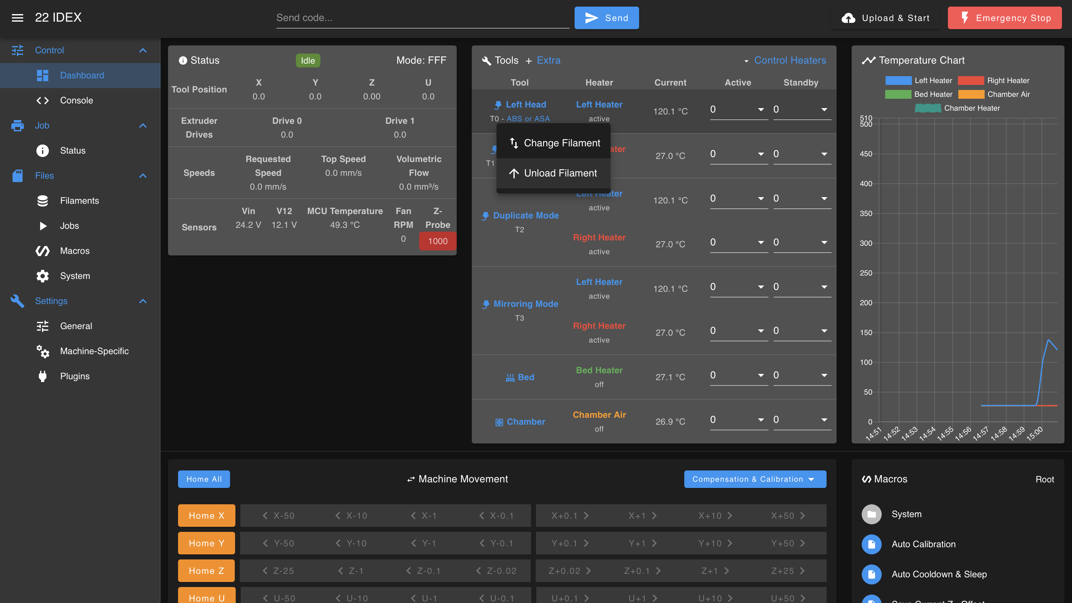
Automatic (Web Interface). With the hotend hot, use either of these controls to retract the filament:
- Tool unload button: next to the active tool (Left Tool / Right Tool), press the unload button that indicates loaded filament. This retracts the filament for that tool.
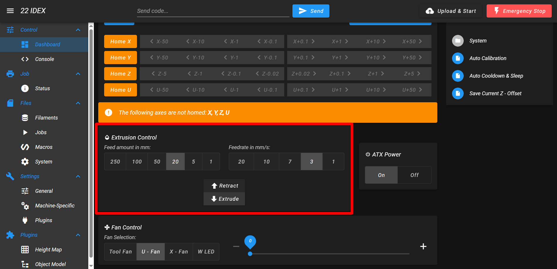
- Extrusion Control: press Retract in the Extrusion Control section, slightly lower in the Web Interface (100 mm at ~7 mm/s).
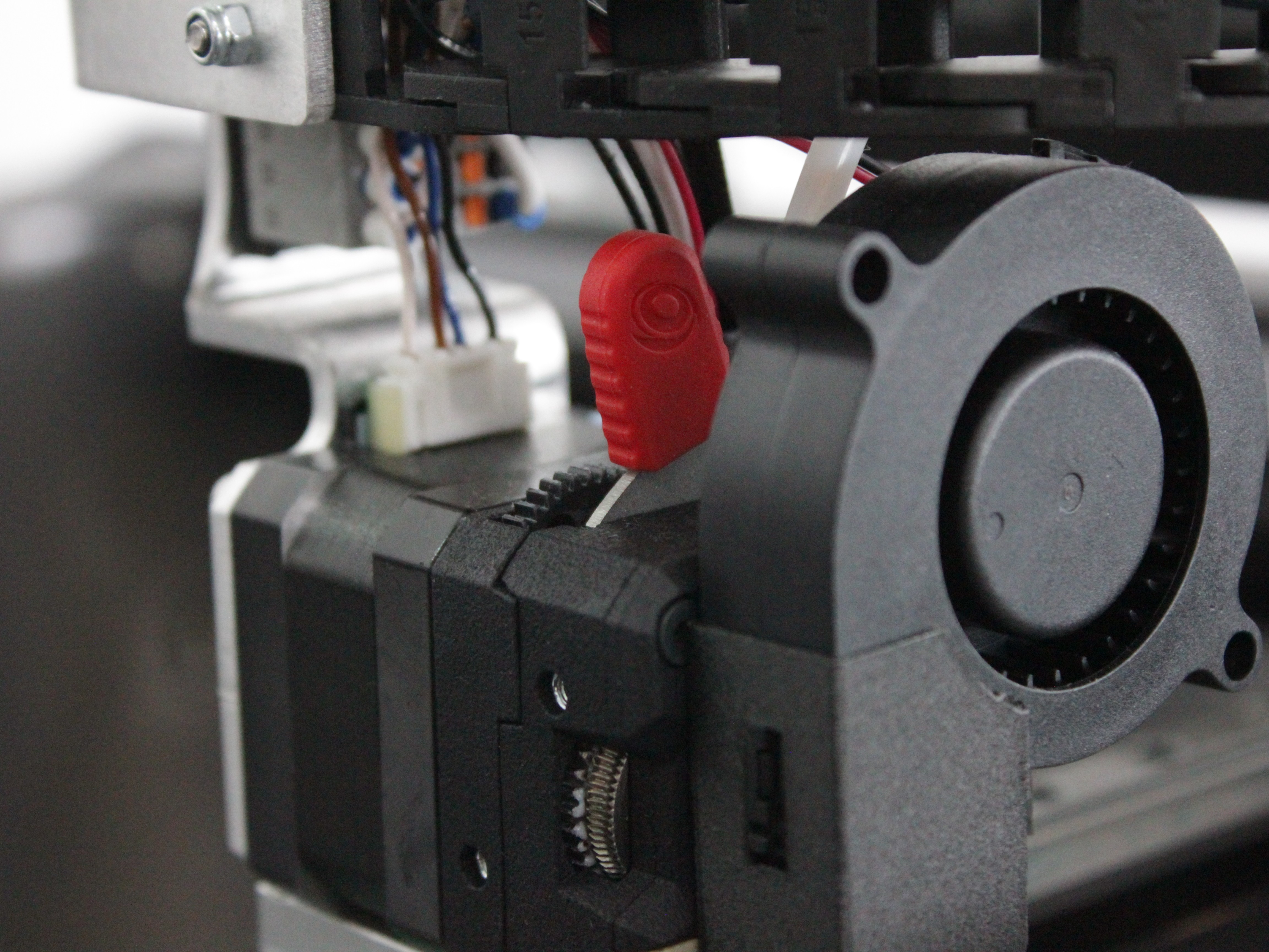
Manual. Preheat the hotend, then push the extruder lever to the position shown below to release tension on the filament, and pull it out by hand.
- Reference: If unsure, see the Filament Loading/Unloading.
Always remove filament while hot
Molten plastic will help prevent clogging or filament residue in the nozzle and heat break.
If filament won't retract
If the filament is stuck or the extruder motor clicks without moving the filament, see Filament Won't Retract in the Troubleshooting section.
2. Removing the Nozzle (While Hot)
- Heat the hotend to printing temperature (or slightly lower, e.g., 20–30°C below standard printing temp).
- Secure the heat block with pliers or an adjustable wrench.
- Unscrew the nozzle clockwise (looking up from the nozzle tip) using a 7 mm wrench.
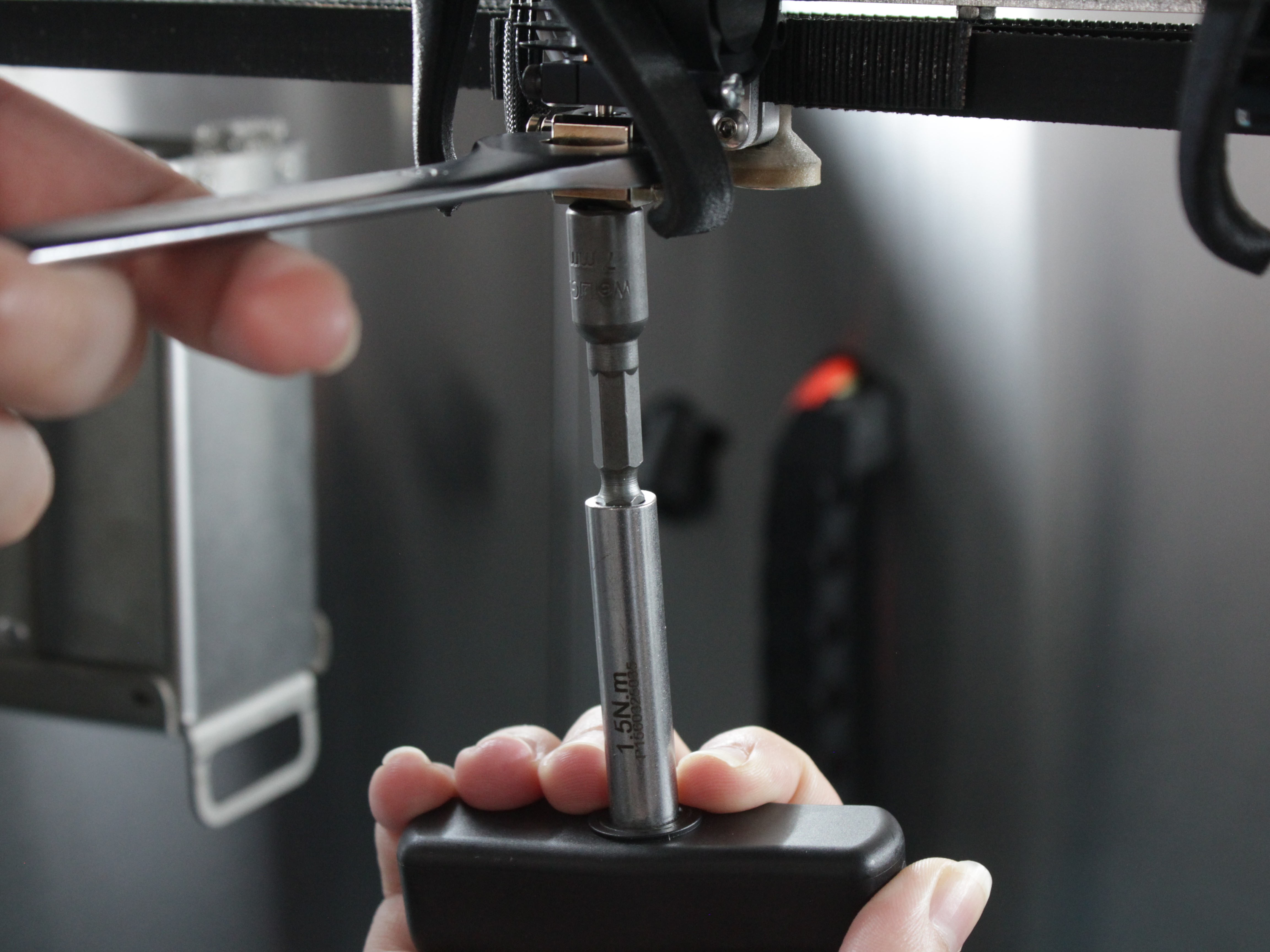
- Caution: The metal components will be extremely hot. Wear heat-resistant gloves and avoid contact with any heated surfaces.
- Cool Down: After nozzle removal, power off and allow everything to cool to a safe handling temperature.
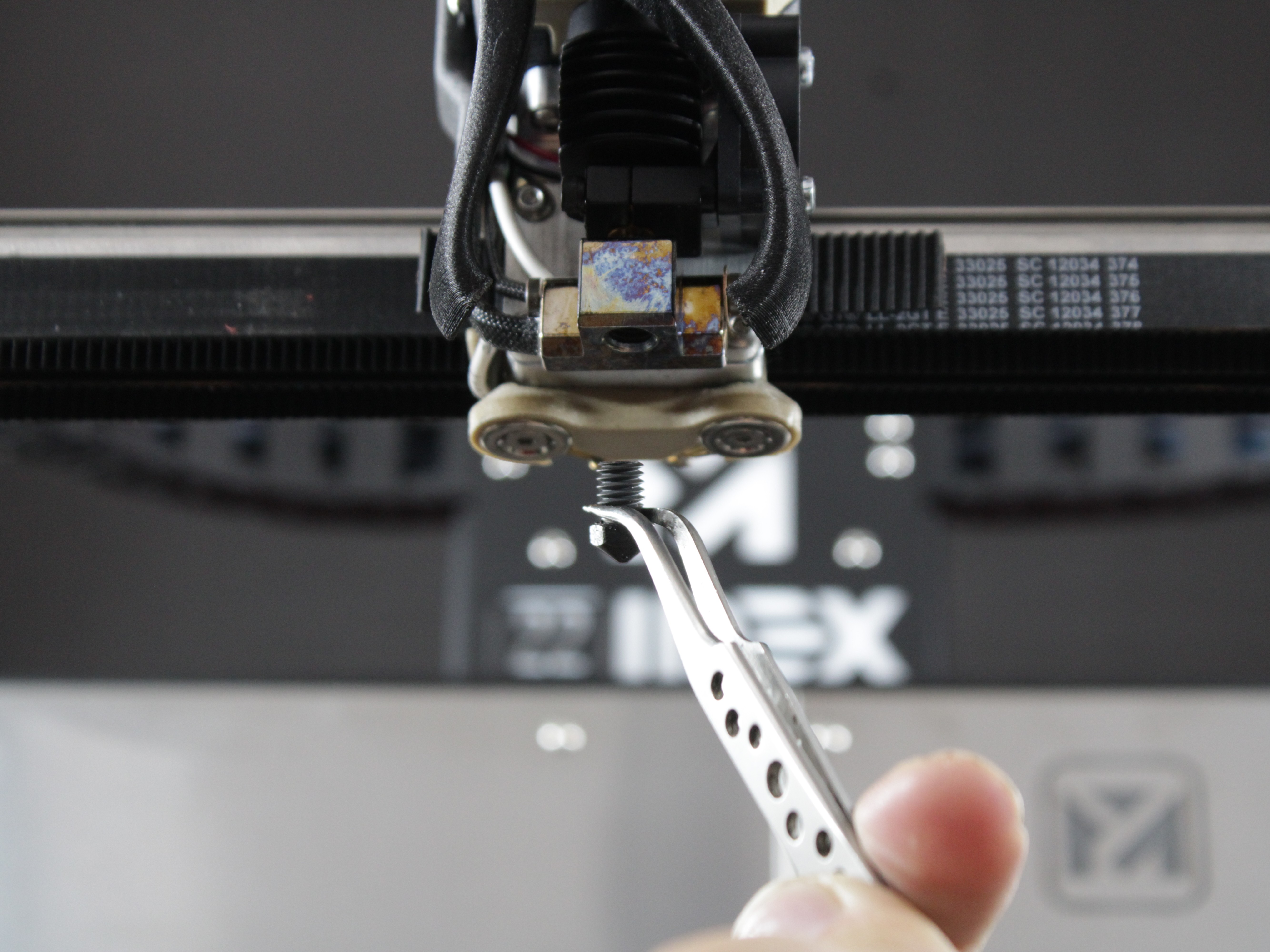
Why remove the nozzle while hot
Removing the nozzle hot prevents hardened filament from binding the threads. This reduces the risk of damaging the heat block or nozzle.
If the nozzle is clogged
If you cannot remove the nozzle or suspect a clog, see Nozzle Still Clogged in the Troubleshooting section.
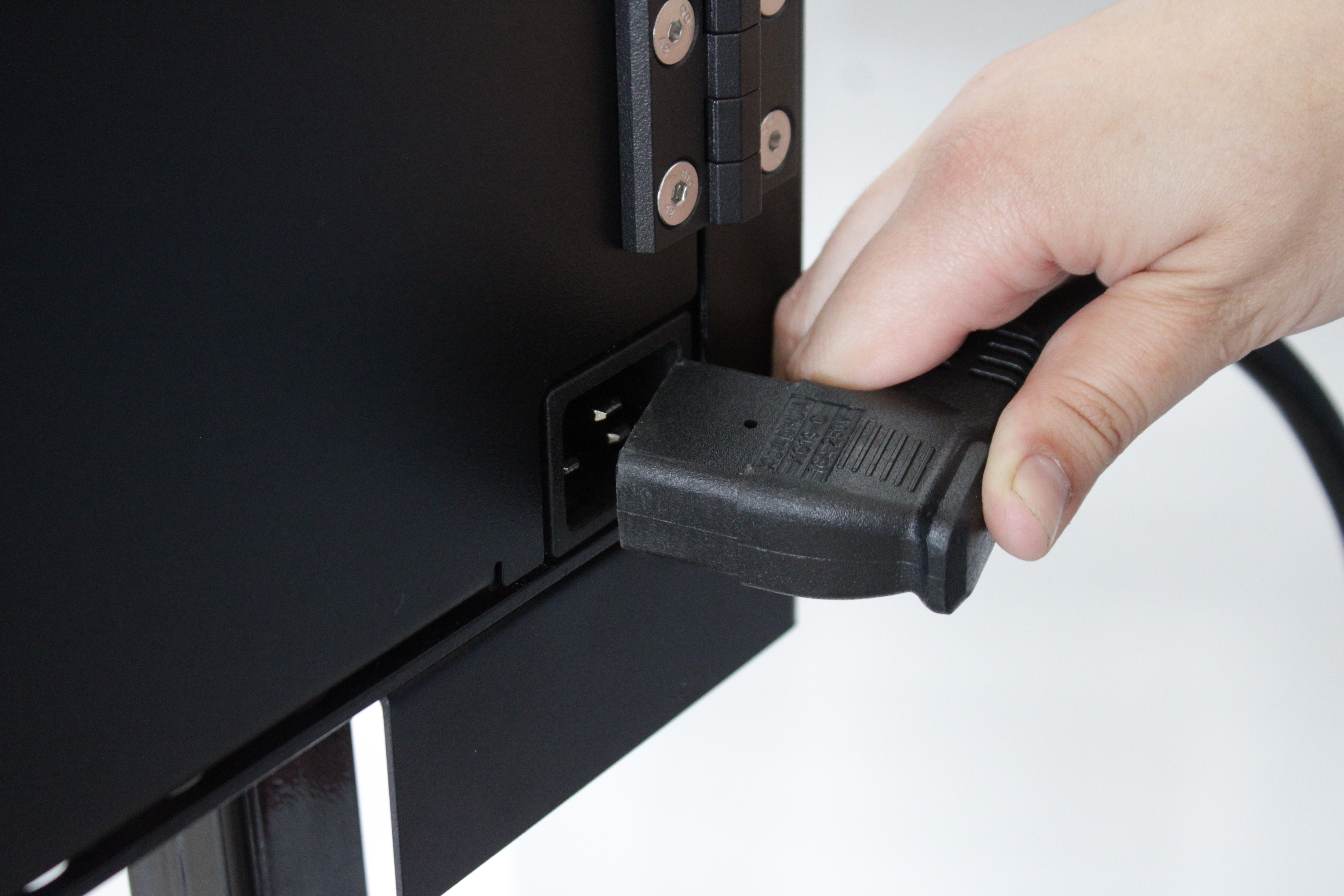
3. Power Off
- Power off the printer by unplugging it from the wall to ensure complete electronic safety.
4. Removing the Fan Shroud
The same two screws hold both the fan shroud and the wire guard.
- Use a 2 mm hex driver to remove the two screws holding the fan shroud in place.
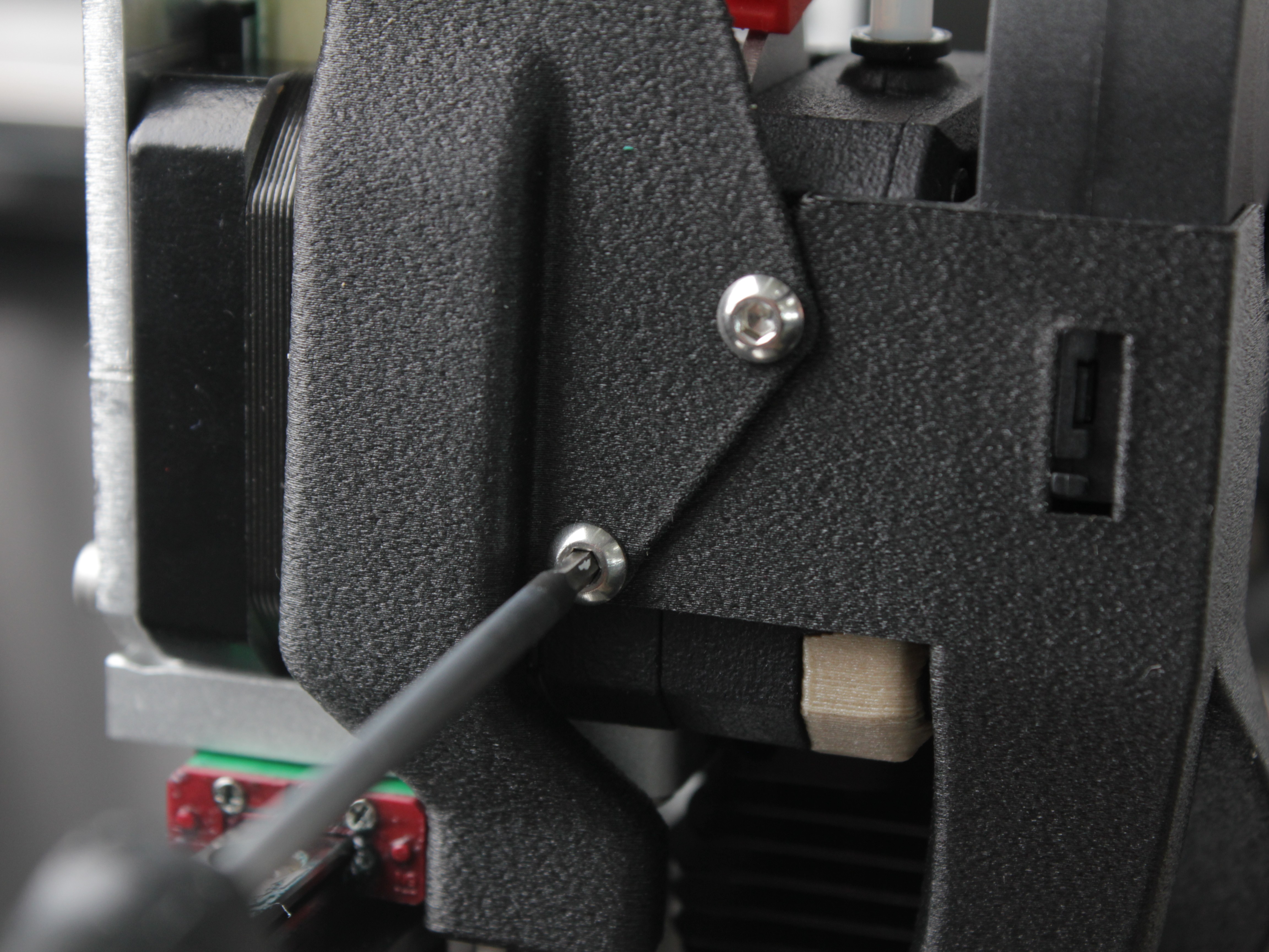
- Carefully move the fan shroud aside, together with the fan, so it does not get in the way during the rest of the disassembly.
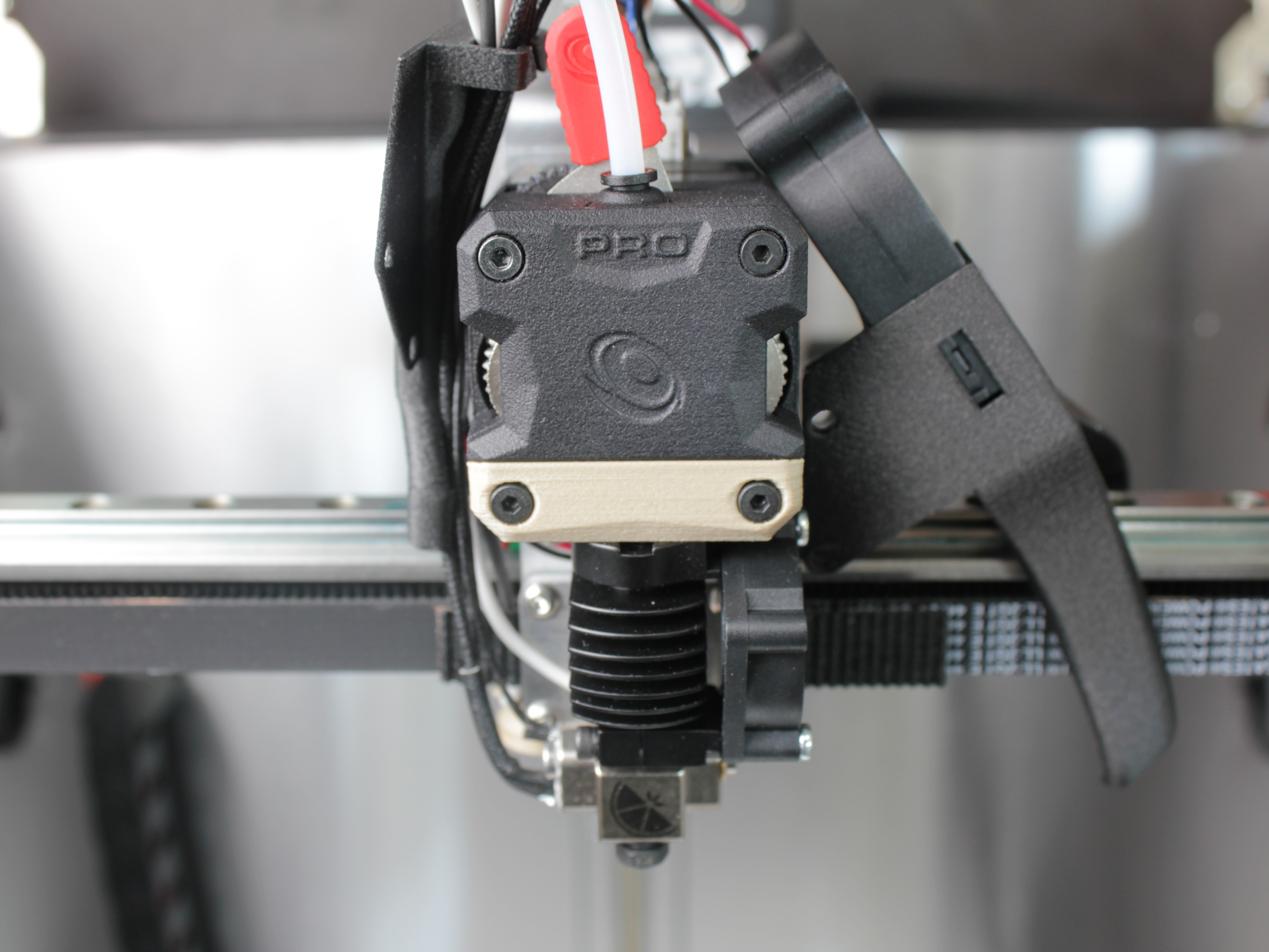
The wire guard stays in place and does not need to be removed.
5. Remove Grounding Wire (Lug Style Crimp)
Before proceeding to remove the hotend assembly, you must disconnect the grounding wire at the hotend.
- Locate the lug-style crimp attached to the hotend body (see picture below).
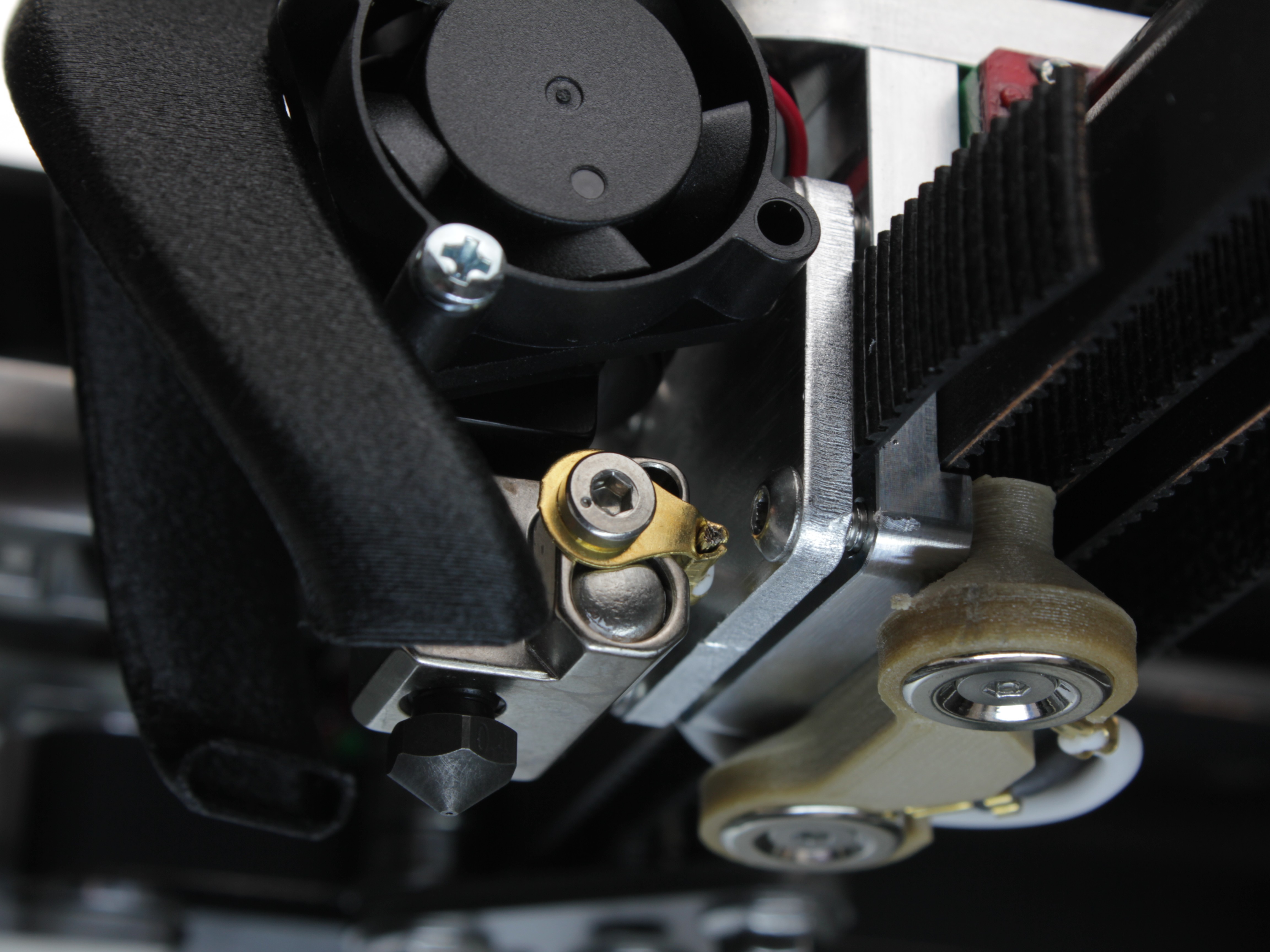
- Using a 2 mm hex screwdriver, remove the screw holding the lug in place.
- Carefully set the grounding wire and lug aside for later reinstallation.
Grounding wire is essential for safety
This wire is essential for proper grounding. Ensure it only contacts the hotend metal surface to avoid electrical issues.
6. Removing the Hotend Assembly
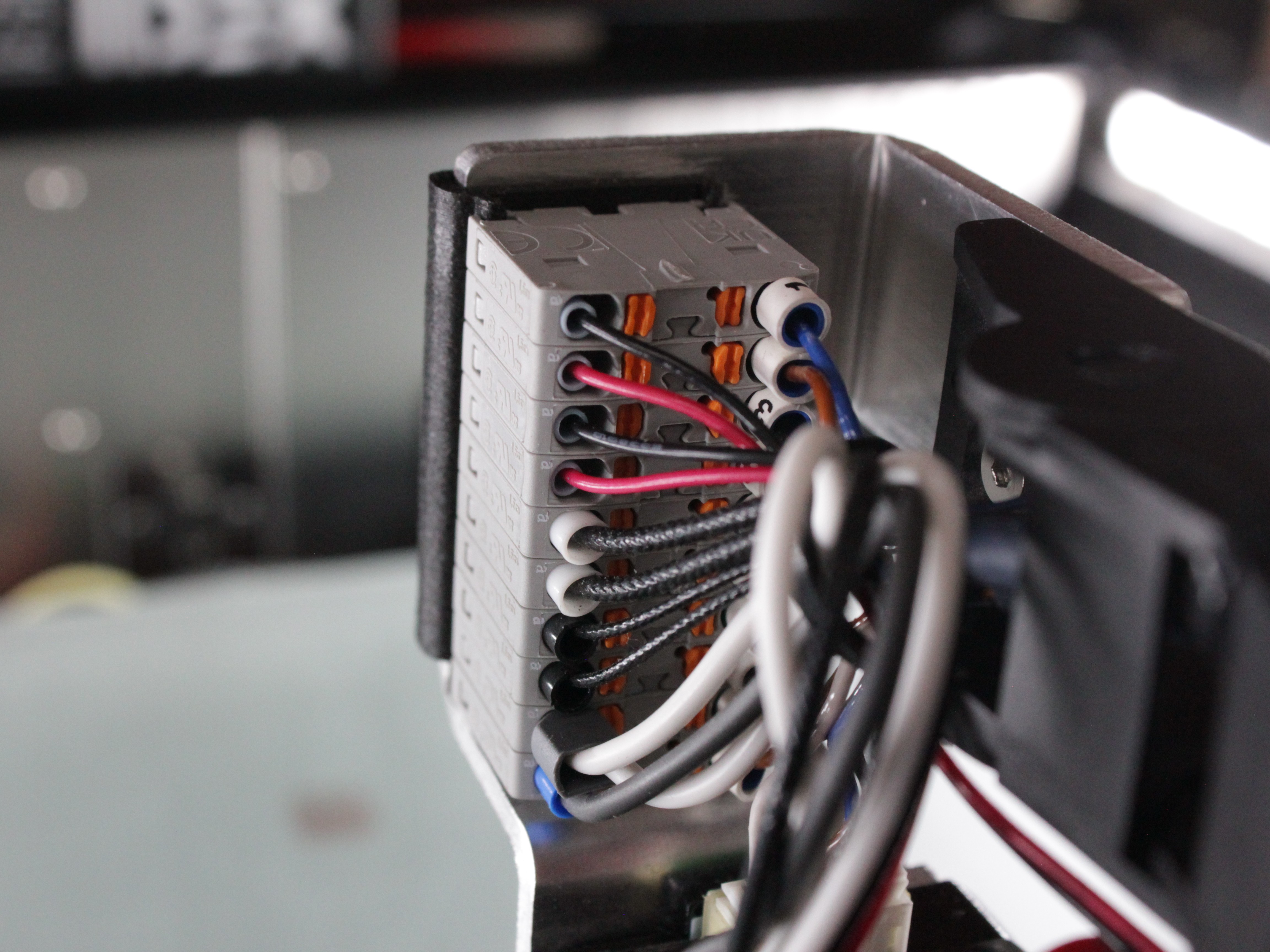
You usually do not need to disconnect the hotend wires. The heater, temperature sensor, and grounding wires all meet at the distribution block shown below. Leave them connected, and disconnect one only if it gets in your way during the next steps.
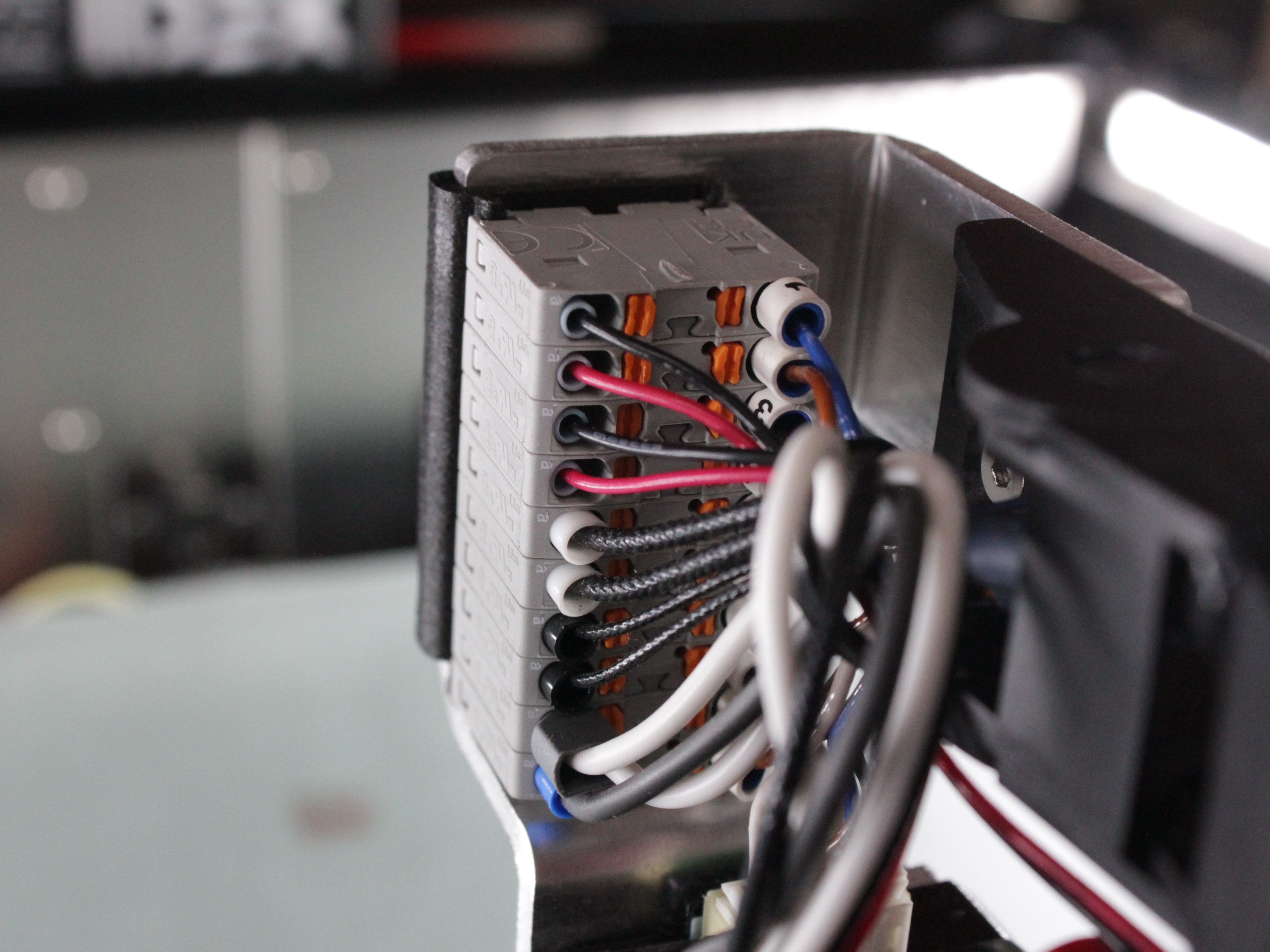
- If a wire is stretched tight and gets in the way as you remove the hotend, disconnect just that wire using steps 16-18. If no wire is in the way, skip to step 19.
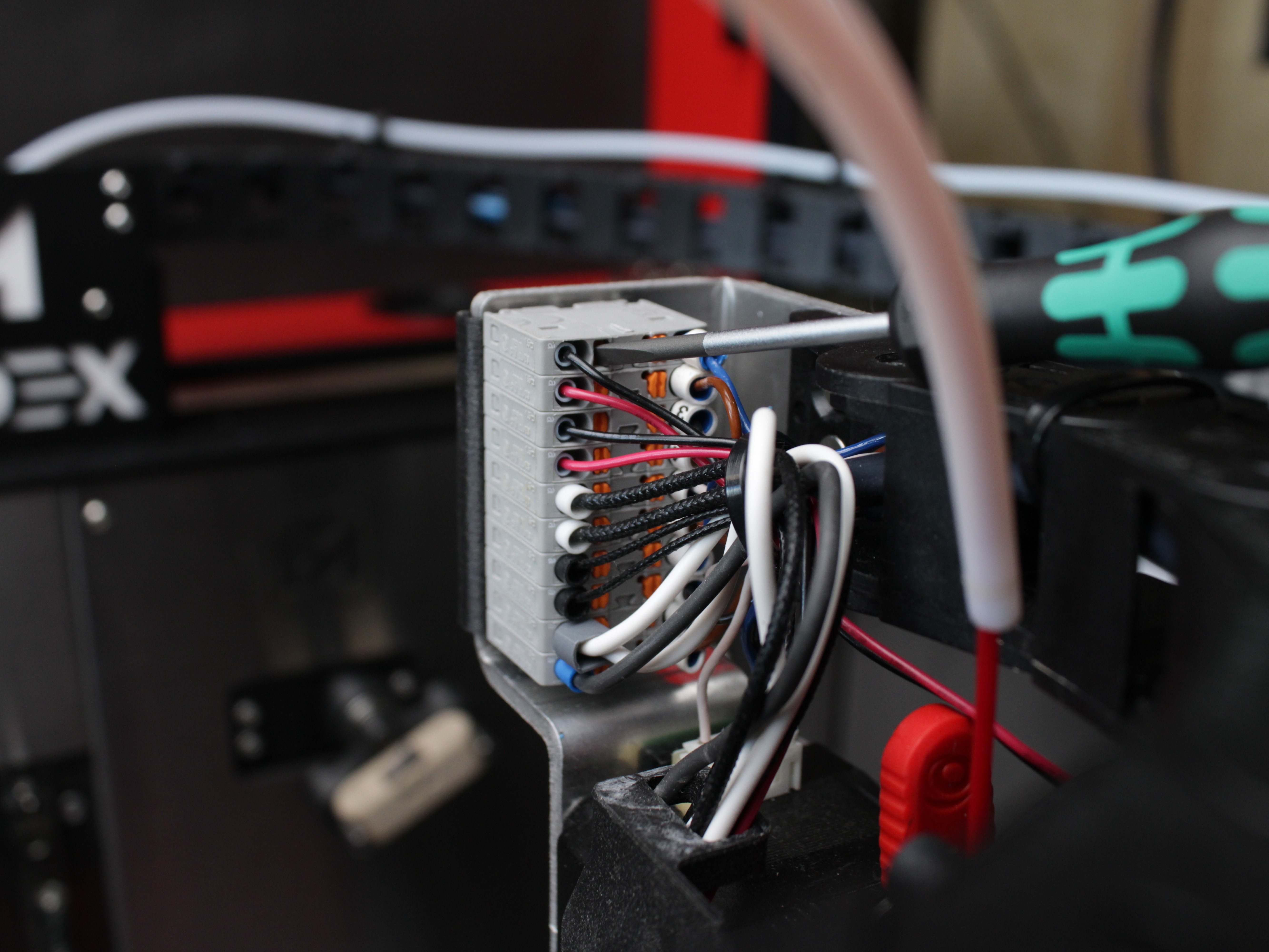
- Using a 2 mm hex screwdriver, press the orange spring-loaded tab inside the distribution block opposite the wire you want to remove.
- Support the distribution block from the back so you do not put force on the tool head.
- With the tab pressed, gently pull the wire straight out. Do not force it.
Document any wire before disconnecting it
If you do disconnect a wire, take a photo or label it first to track polarity and where it reconnects. See the Wiring Schematic for reference.
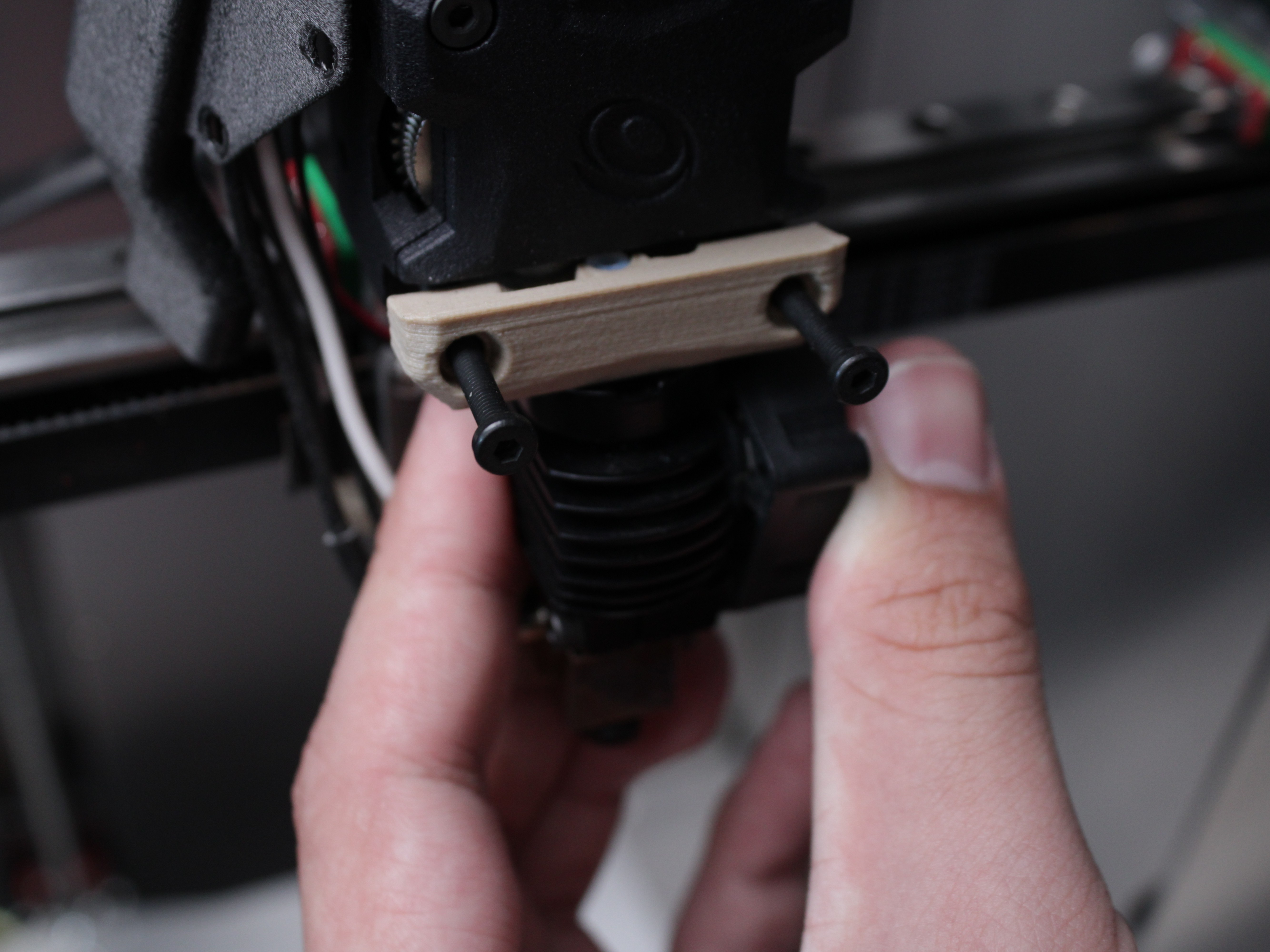
- Extruder Front Plate:
- Using a 2 mm hex driver, fully unscrew the two marked screws shown in the photo. Remove them completely.
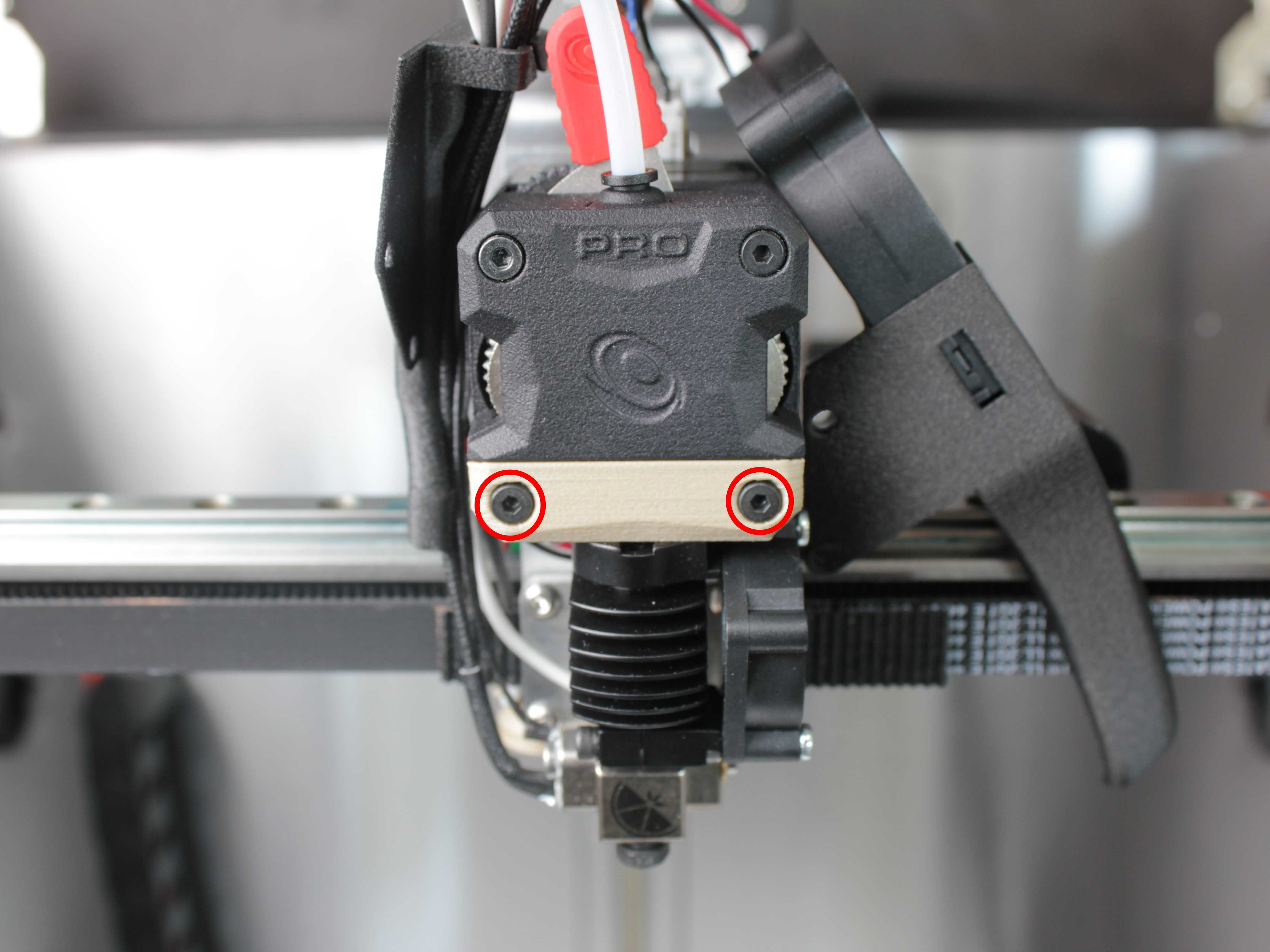
- Slide Out the Hotend:
- Pull the hotend toward you (forward).
- If the hotend doesn't slide out easily, gently shake it from side to side while pulling it towards you.
- Check for stray filament or debris that might prevent smooth removal.
7. Disassembling the Hotend
Once the hotend is free from the extruder, you can break it down into its core parts.
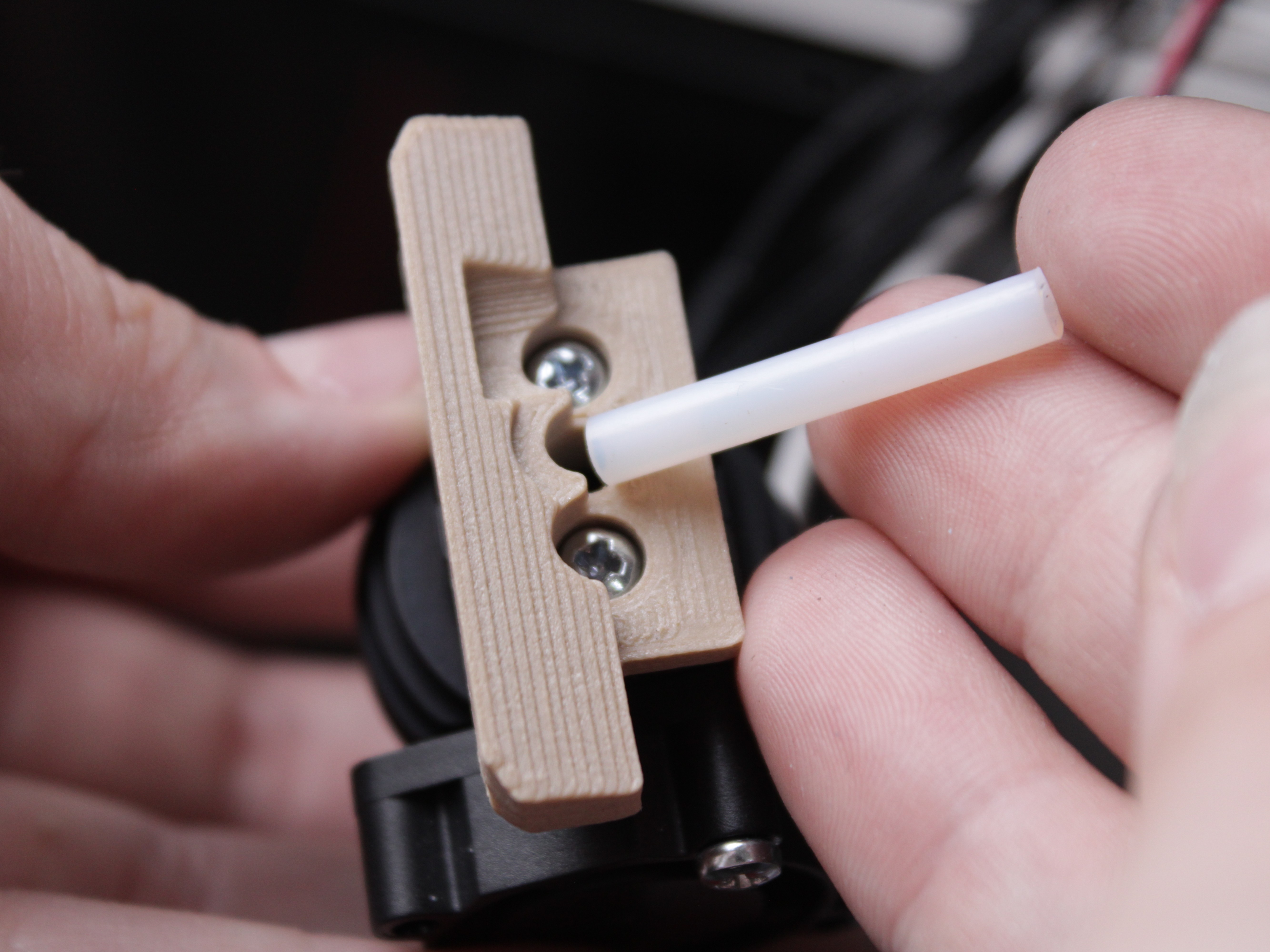
- PTFE Tube:
- Carefully pull the PTFE tube out with tweezers, taking care not to damage it. It should come out with little effort.
- If it resists, skip this step for now and remove the tube after you unscrew the printed interface plate (next step).
- Inspect the tube: it should be flush and cut to the correct length. Replace it if it is damaged or too short.
- 3D Printed Interface/Adapter:
- Using a 2 mm hex driver, remove the two screws holding the interface plate.
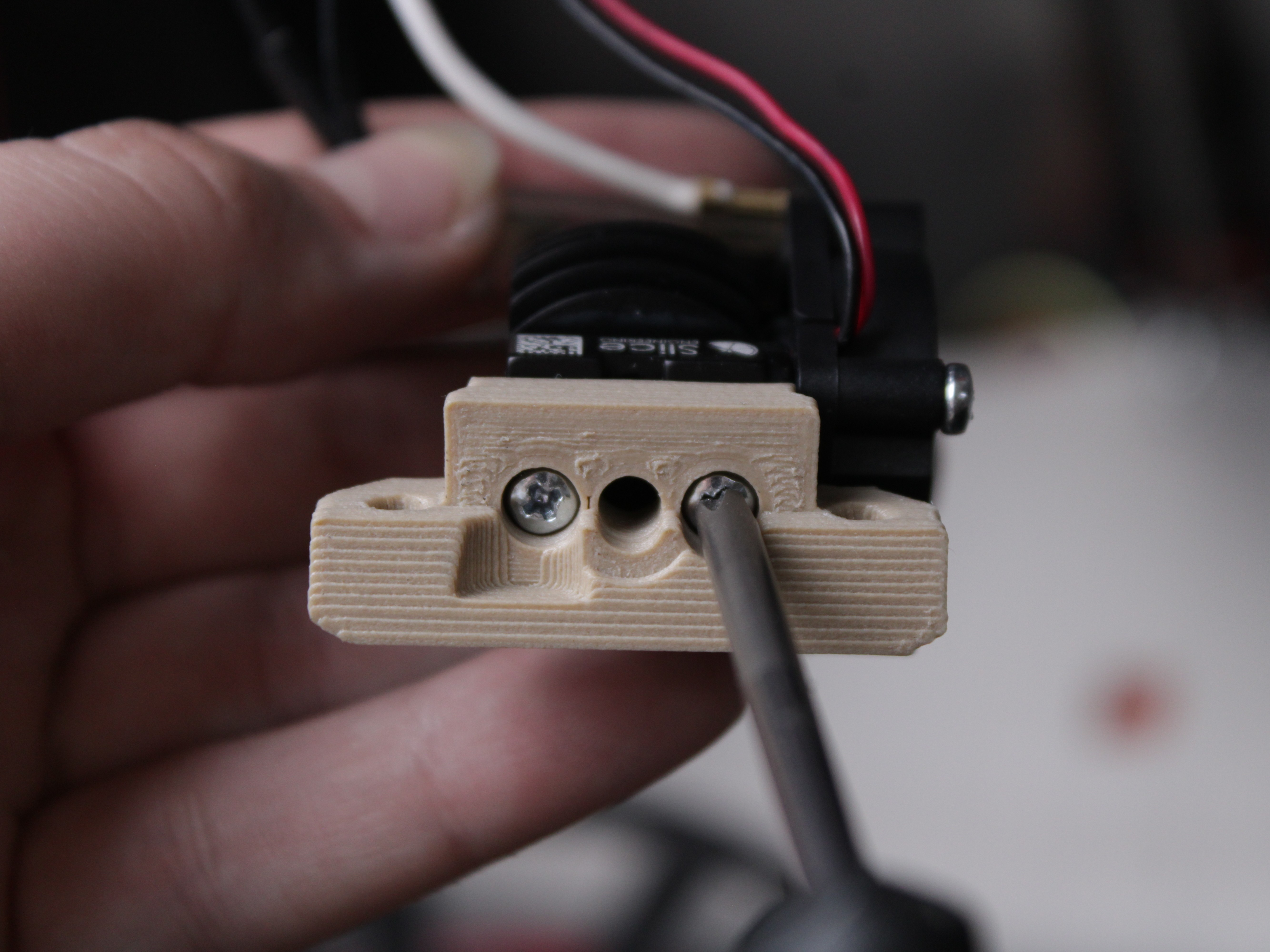
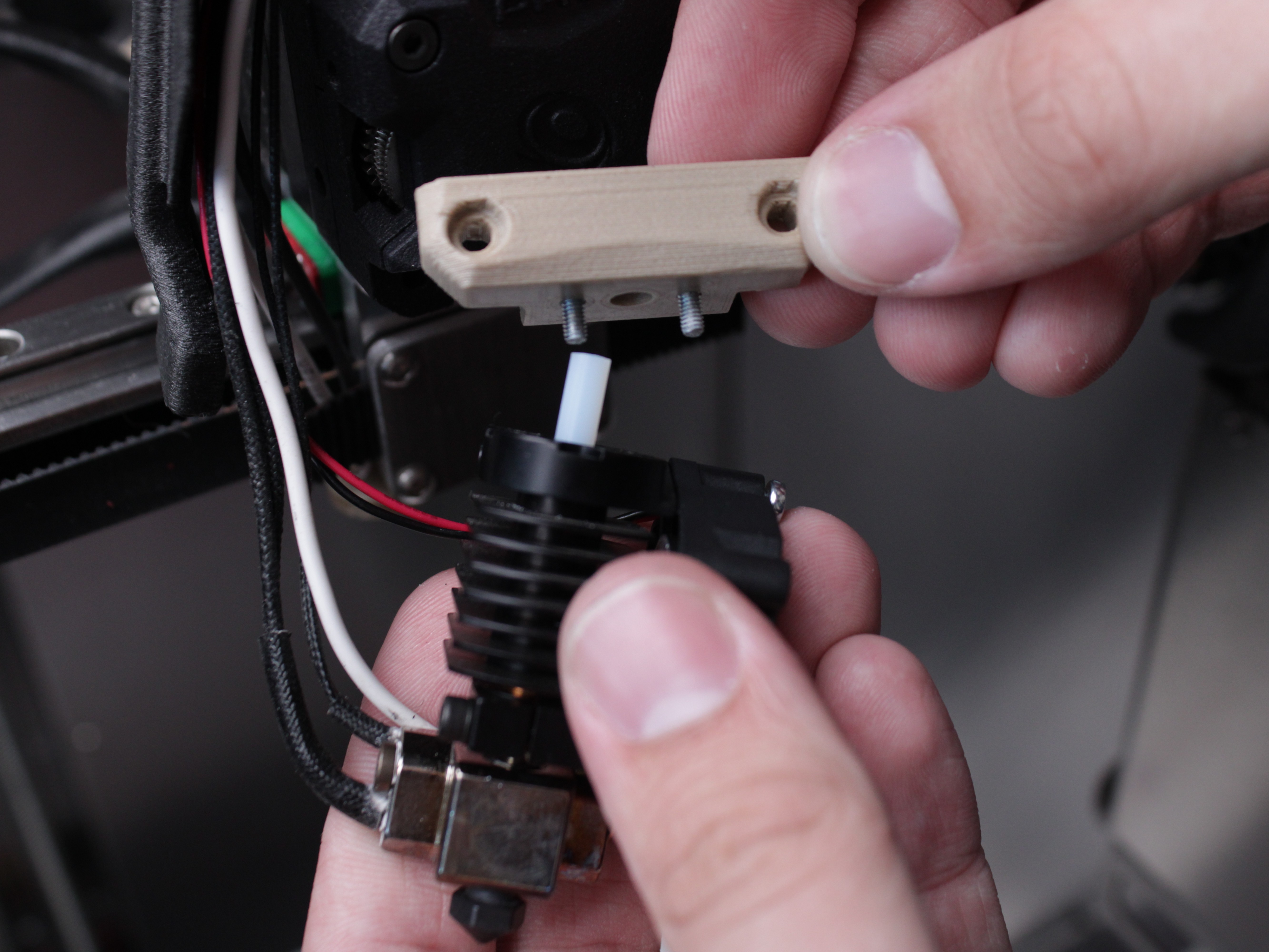
- Separate the interface plate from the radiator.
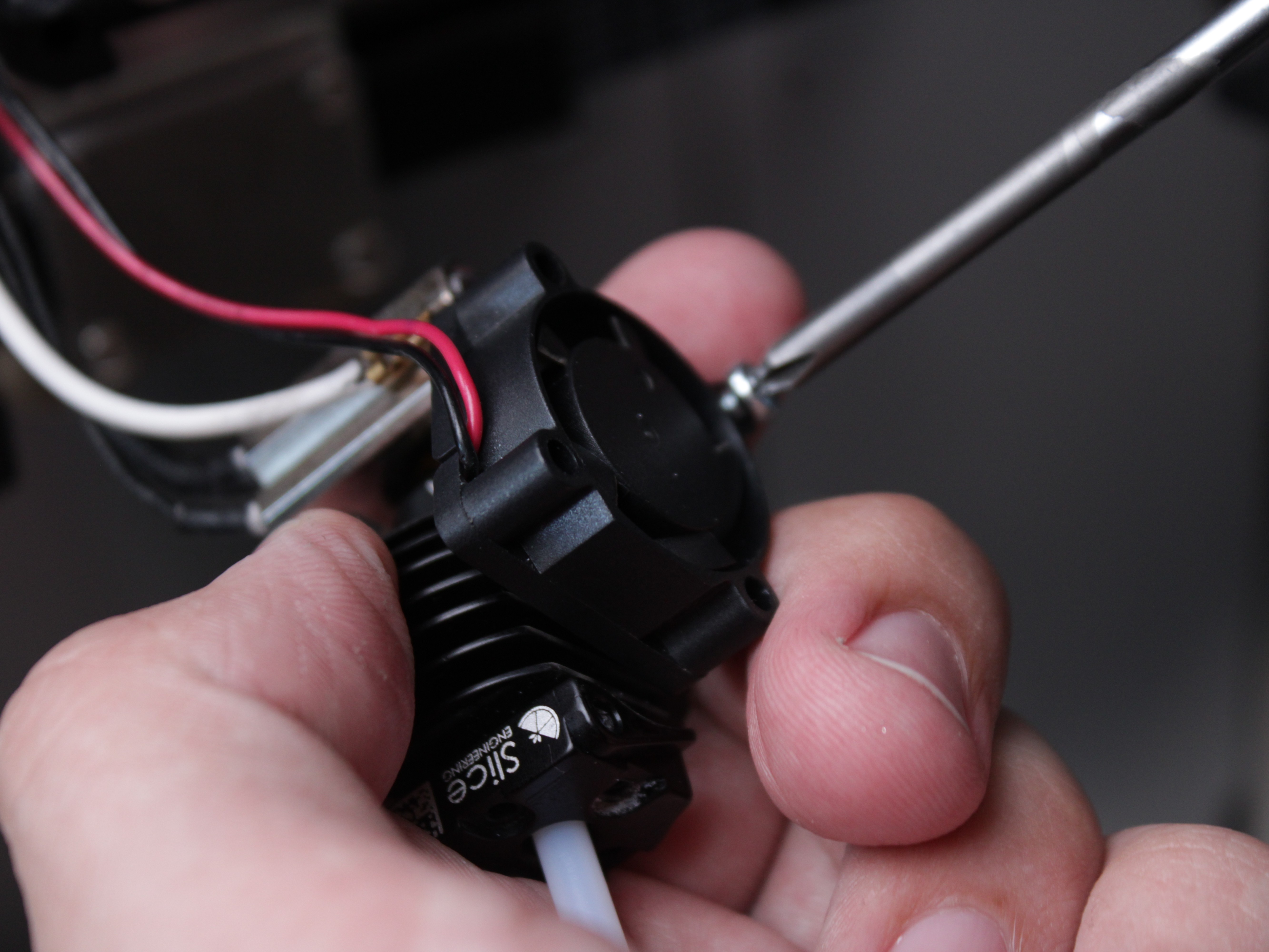
- Cooling Fan:
- Unscrew 2 screws and remove the fan.
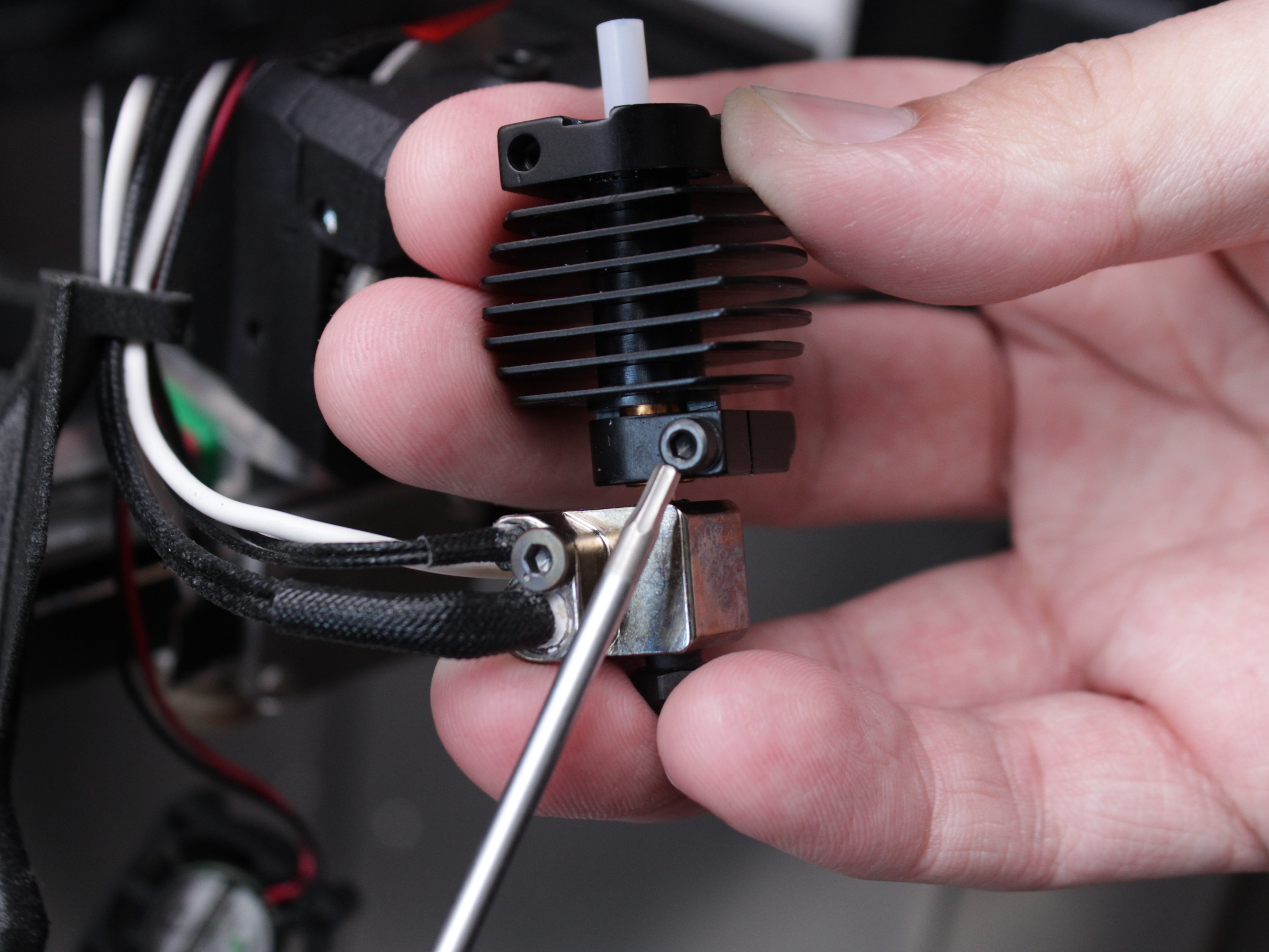
- Radiator:
- Loosen the screw on the radiator and remove it.
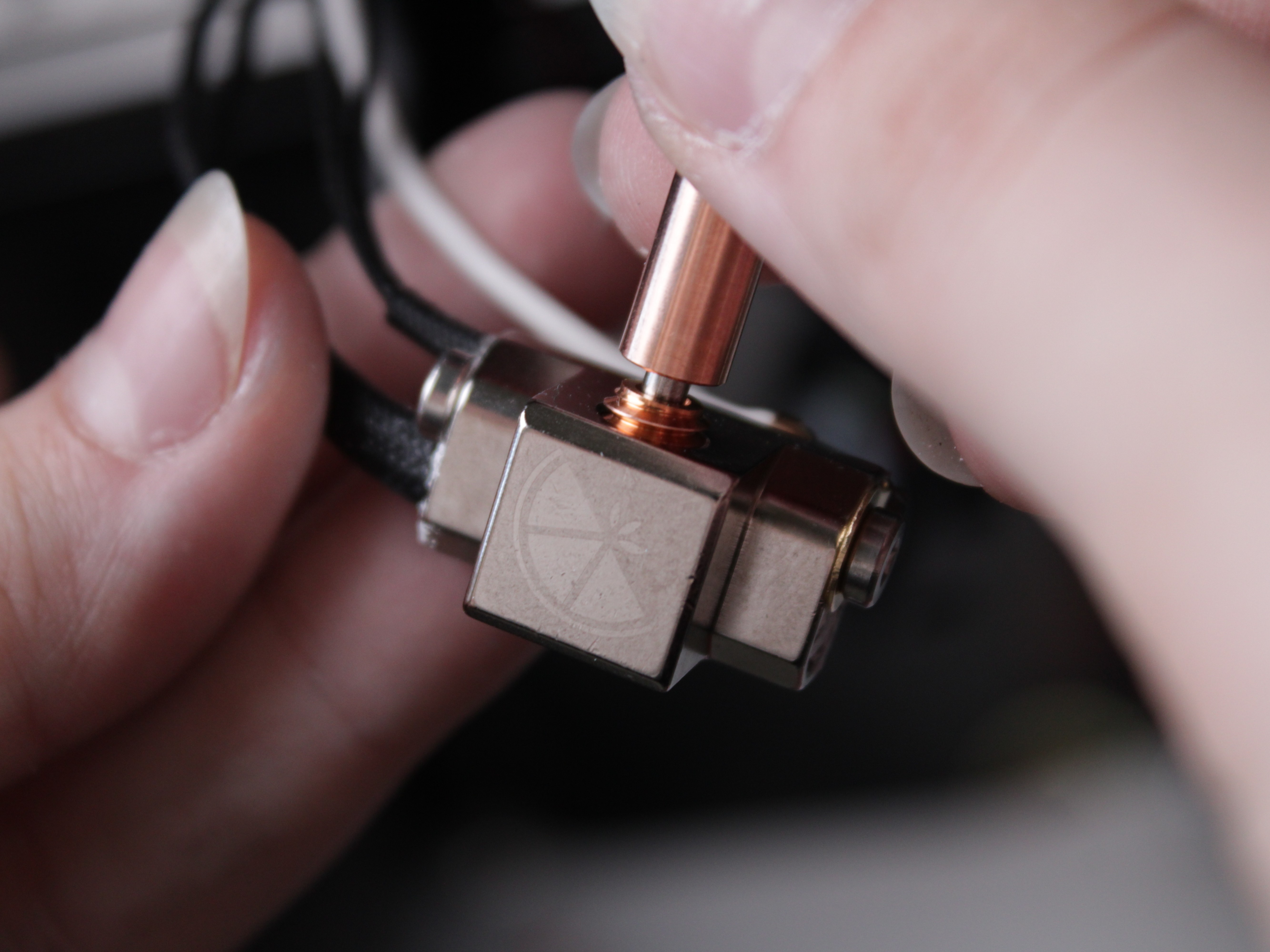
- Heat Break:
- Unscrew the heat break. If it will not come loose by hand, see the heating tip below.
- Heater Cartridge & Temperature Sensor:
- Fully unscrew the set screw that holds the temperature sensor and the heater cartridge in the heat block. Do not just loosen it, take it all the way out.
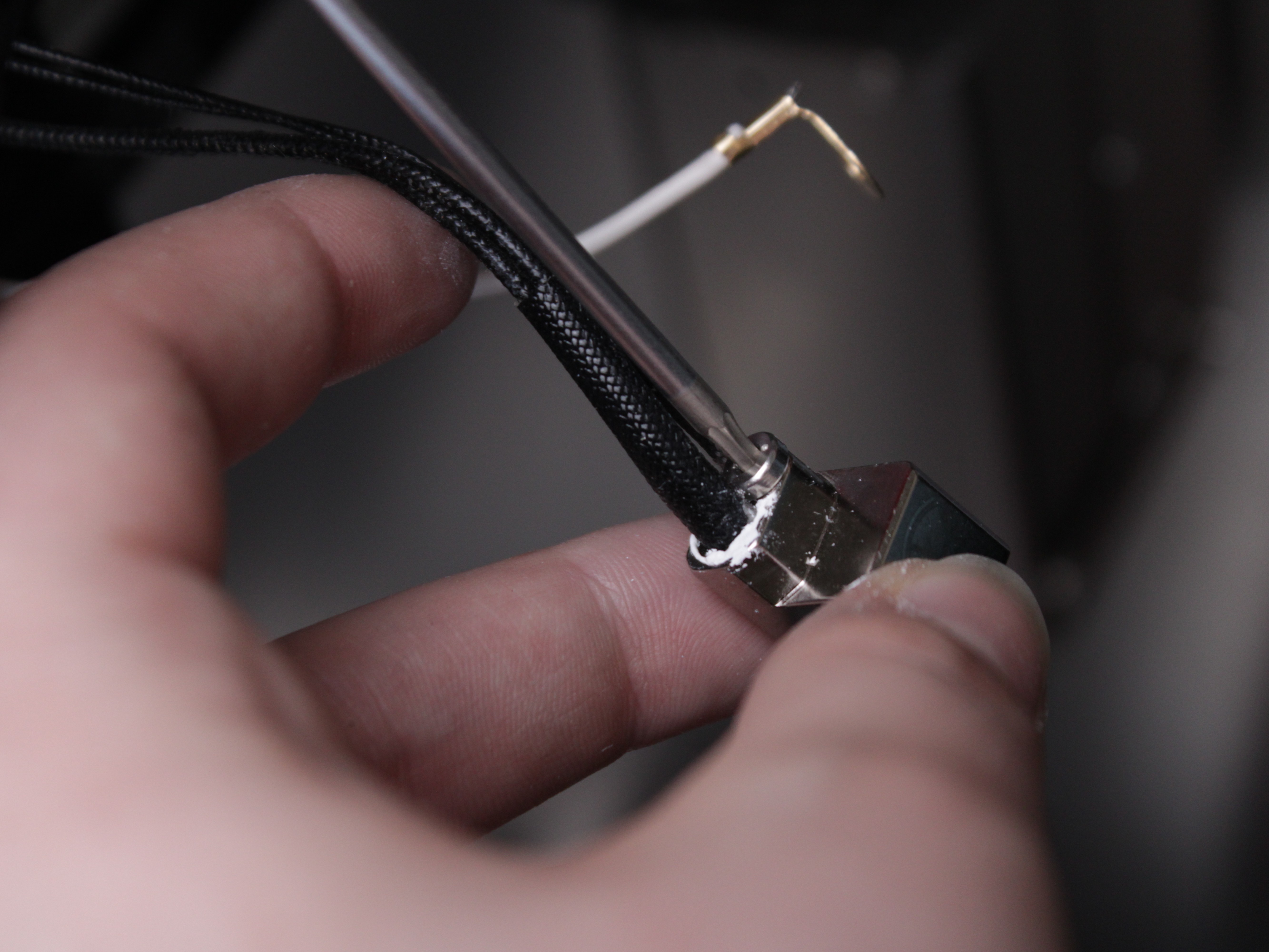
- Gently slide out the heater cartridge and temperature sensor for inspection or replacement. If they will not slide out easily, see the heating tip below.
If the heat break, heater, or sensor will not come loose by hand
These parts can be hard to remove because the boron nitride paste that improves heat transfer also makes them stick. Do not force them.
- Plug the printer back in and heat the tool to about 150–200°C to soften the residue.
- Wearing heat-resistant gloves, hold the heat block only with a gloved hand and carefully work the part free.
- When finished, let the printer cool down, then power it off before continuing.
The metal parts will be hot. Work slowly and carefully.
Inspect wiring and apply thermal paste
- Grounding Wire: Check if the grounding wire is worn out, burned, or excessively bent due to heat exposure. Replace if damaged.
- Fan Wires, Sensor Wires, Heater Wires: Ensure no fraying, burning, or other damage.
- Tip: Apply Boron Nitride/Thermal Paste to threads and surfaces (nozzle, heat break, sensor, heater) as needed for heat conduction and easier future removal.
8. Reassembling the Hotend
Reverse the disassembly steps:
- Install or Replace the Temperature Sensor & Heater:
- Lightly coat each component with thermal paste.
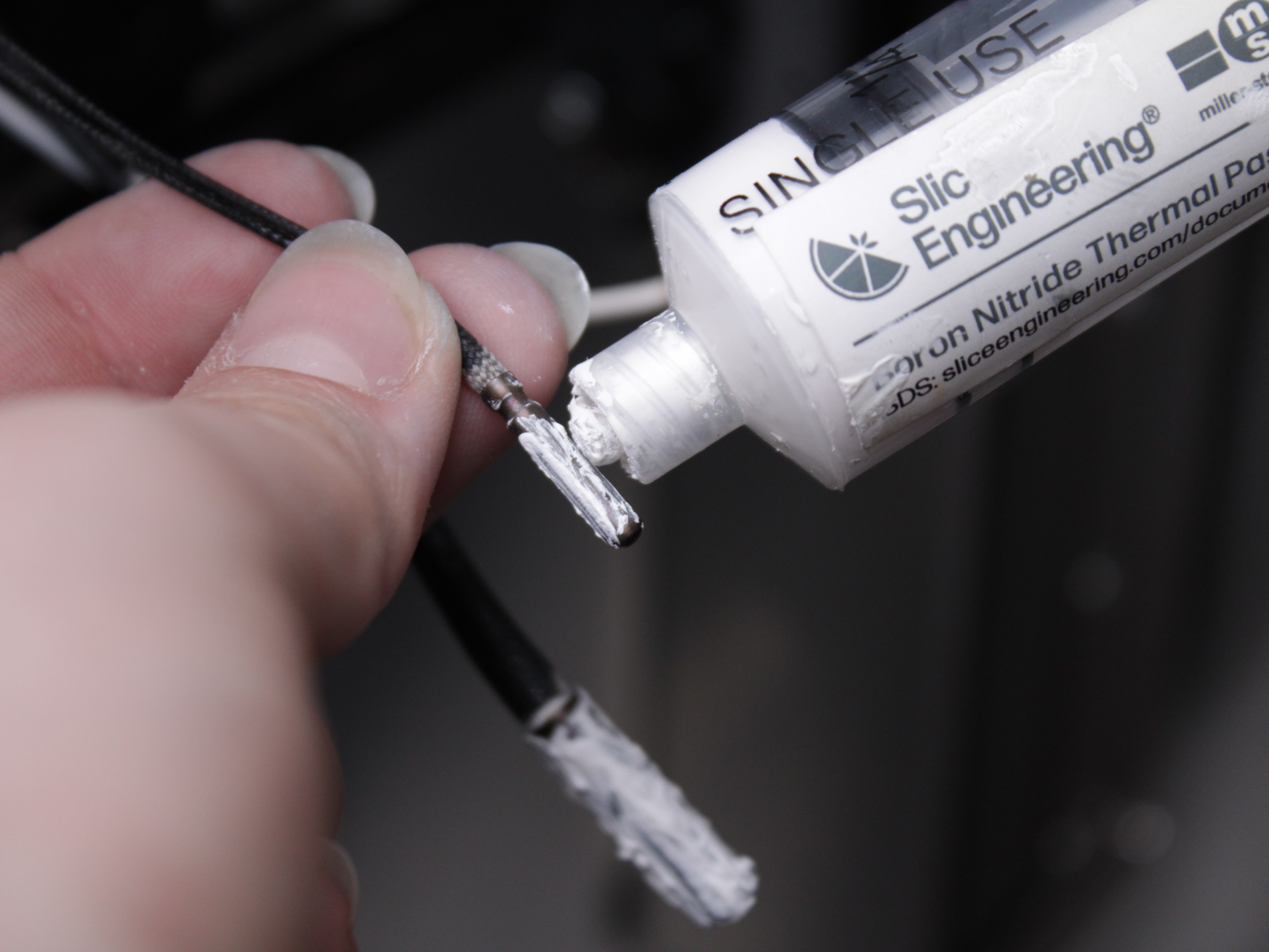
- Slide them into the heat block.
- Secure with the set screw (do not overtighten).
- Attach the Heat Break:
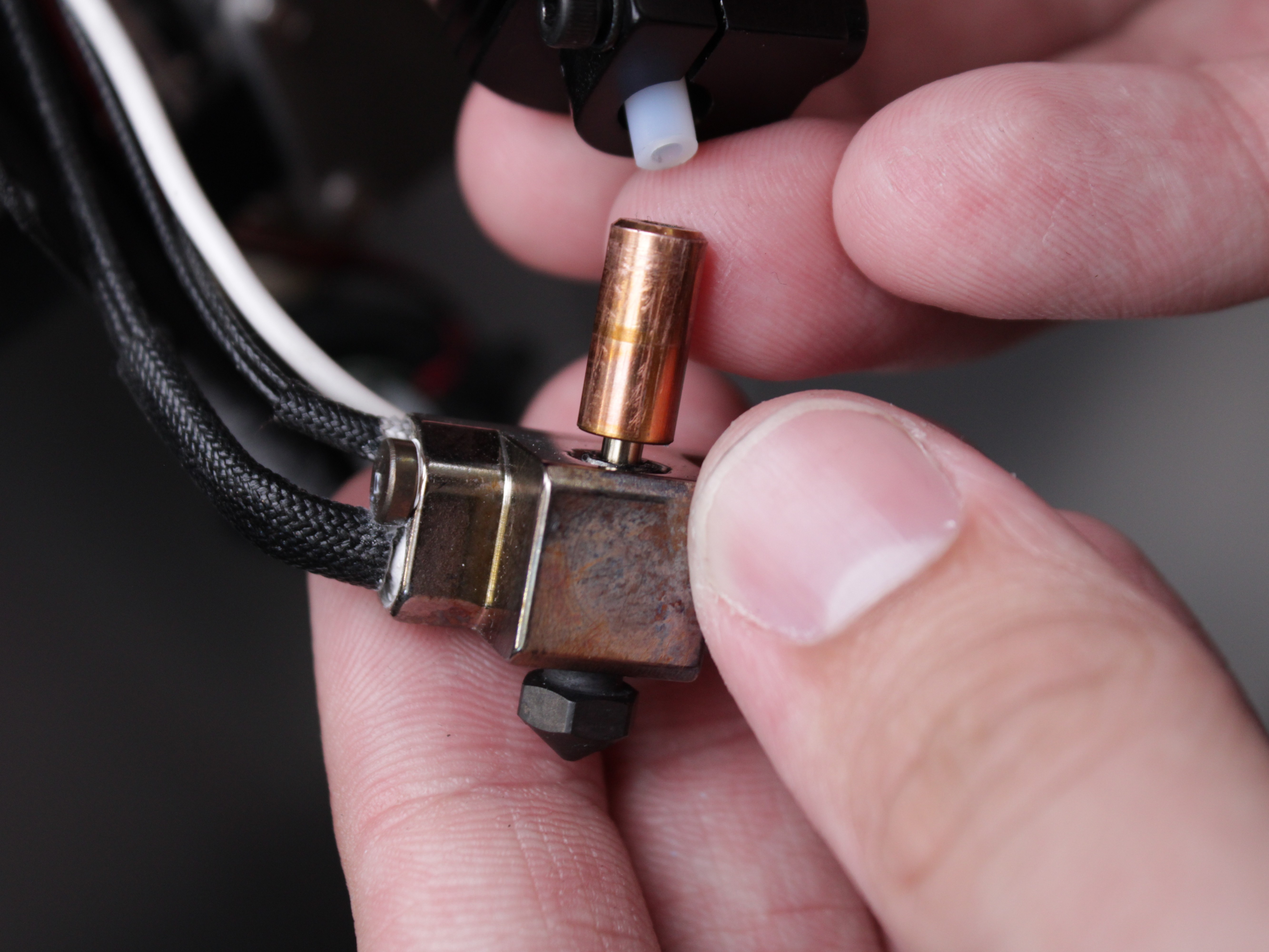
- Thread the heat break into the heat block finger-tight. Avoid applying torque to the thin heat break walls. Screw it in until the edge of the heat break's threaded boss sits flush with the edge of the heat block - the threads allow it to go deeper, but a deeper heat break makes the assembly incorrect.
- If using a Copperhead® or similar, refer to the manufacturer's instructions for correct orientation/fit.
- Reattach the Radiator:
- Slide the heat break into the radiator.
- Tighten the set screw carefully.

- Reattach the Cooling Fan:
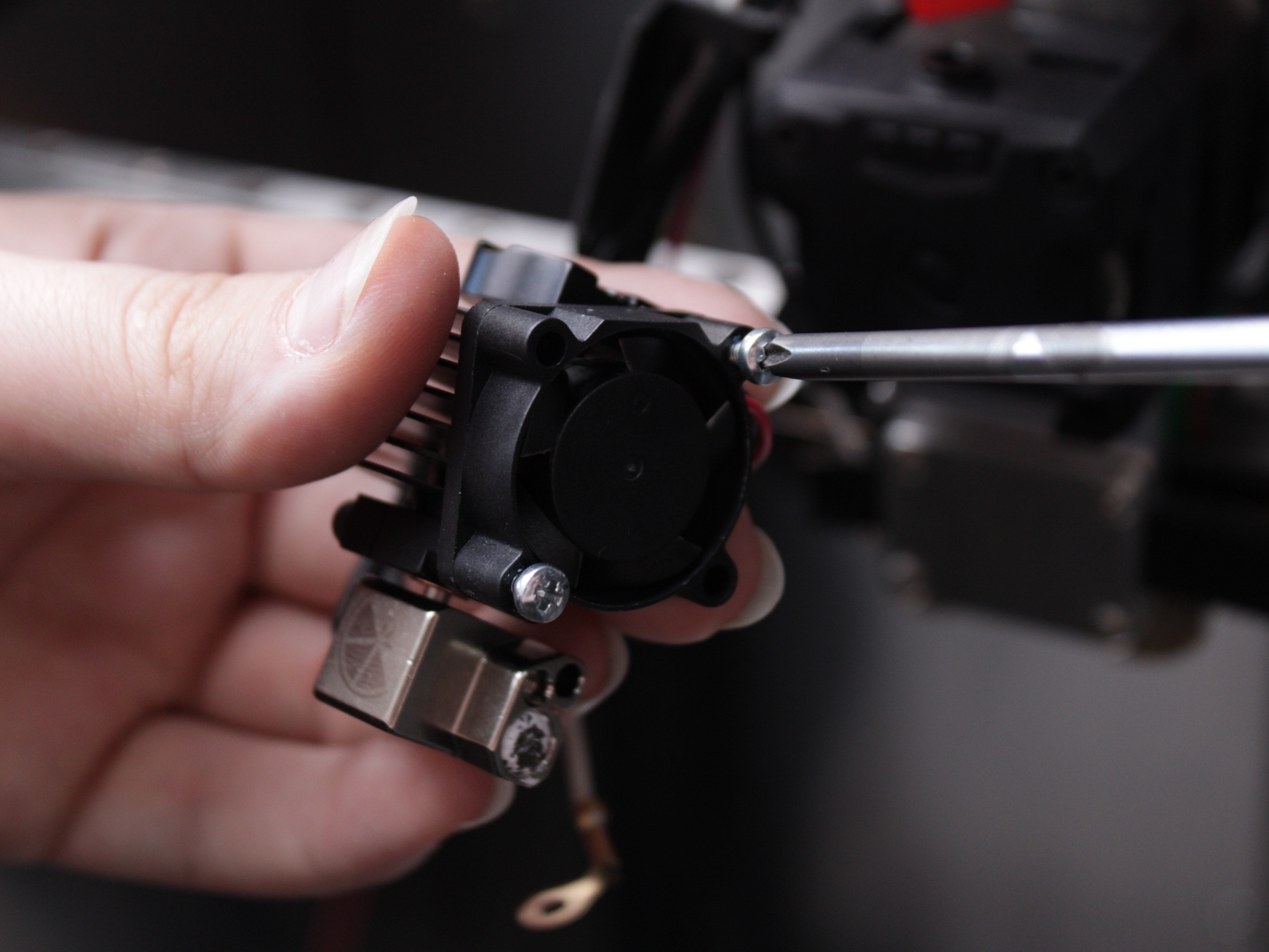
- Attach the fan to the radiator.
- Reattach 3D Printed Interface Plate and PTFE Tube:
- Attach the interface plate to the radiator.
- Reinsert PTFE tube. Ensure correct length and flush fit. This prevents gaps that cause clogs.
Additional reference
For more details on sensor and heater installation or wiring inspection, see Hotend Temp Sensor & Heater Maintenance.
9. Reinstalling the Hotend Assembly
- Slide the Hotend back into the extruder grooves.
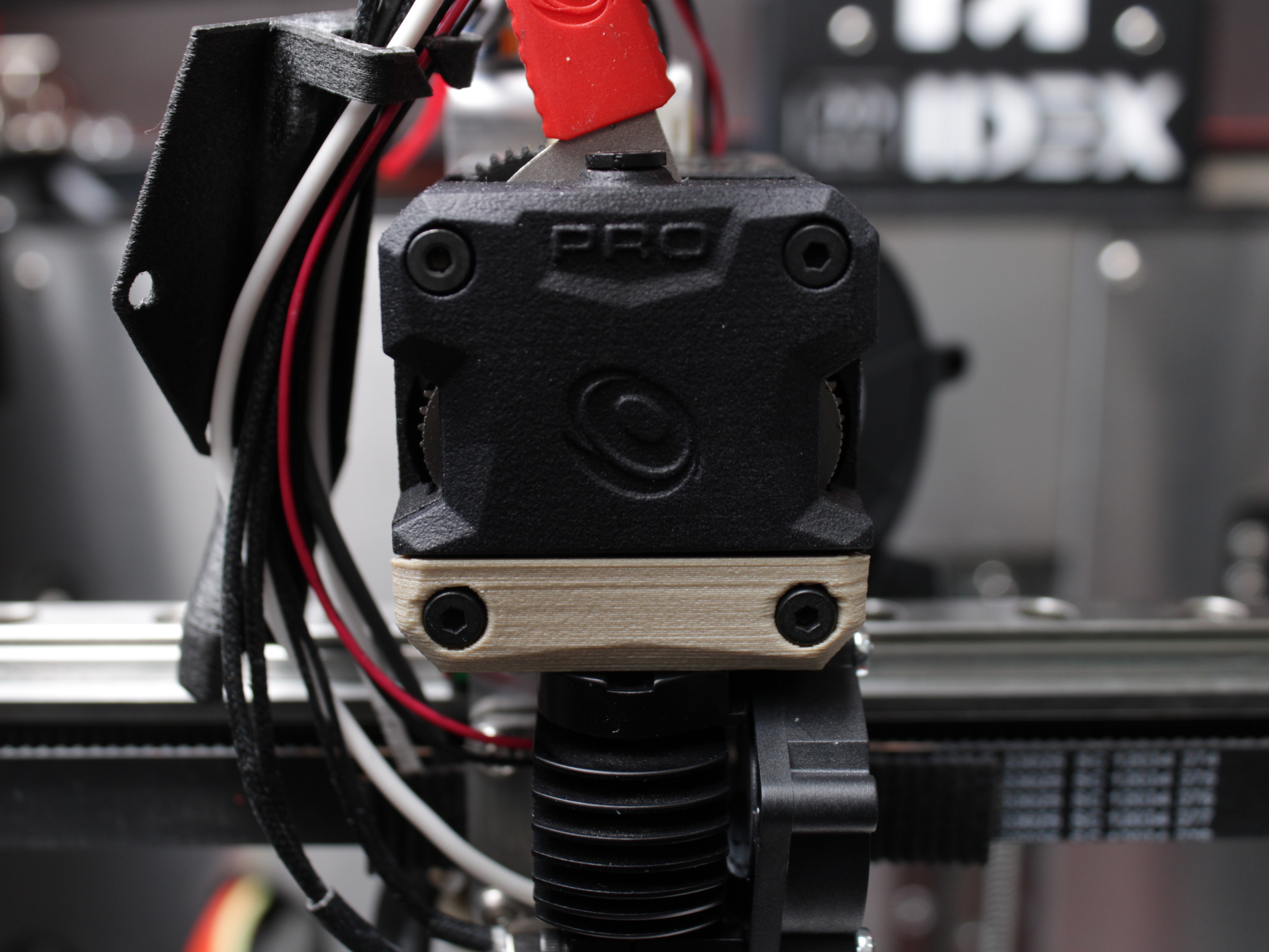
- Secure it with the original screws on the front plate.
- Reconnect the Grounding Wire:
- Fasten the grounding wire to the hotend body using the 2 mm hex driver.
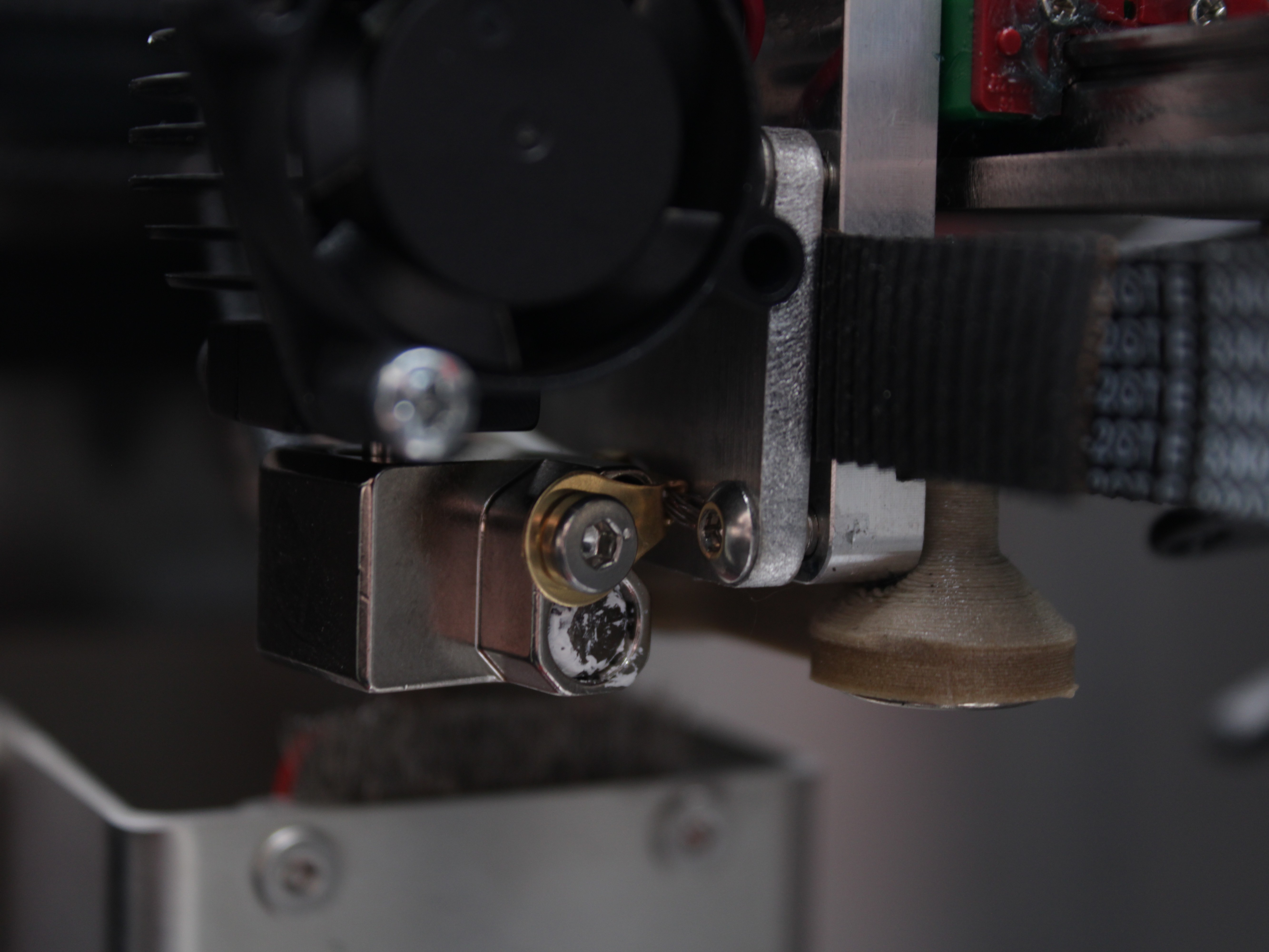
Grounding wire must only touch hotend metal
This wire must not touch any other metal components except the hotend itself. If it does, Z-Probe (ground detection) may fail, and you risk damaging your printer.
- Reconnect Other Wires:
- Reconnect each wire to the same terminal it came from. The heater cartridge and temperature sensor are not polarity-sensitive, so their orientation does not matter. The fan wires are polarity-sensitive - use your reference photo or the Wiring Schematic to connect the fans the right way around.
Only if you disconnected wires earlier
If you unplugged any wires at the distribution block during disassembly, reconnect them now exactly as they were originally, matching the correct positions and polarity. If you left the wires connected, you can skip this step.
- Reinstall Fan Shroud & Wire Guard:
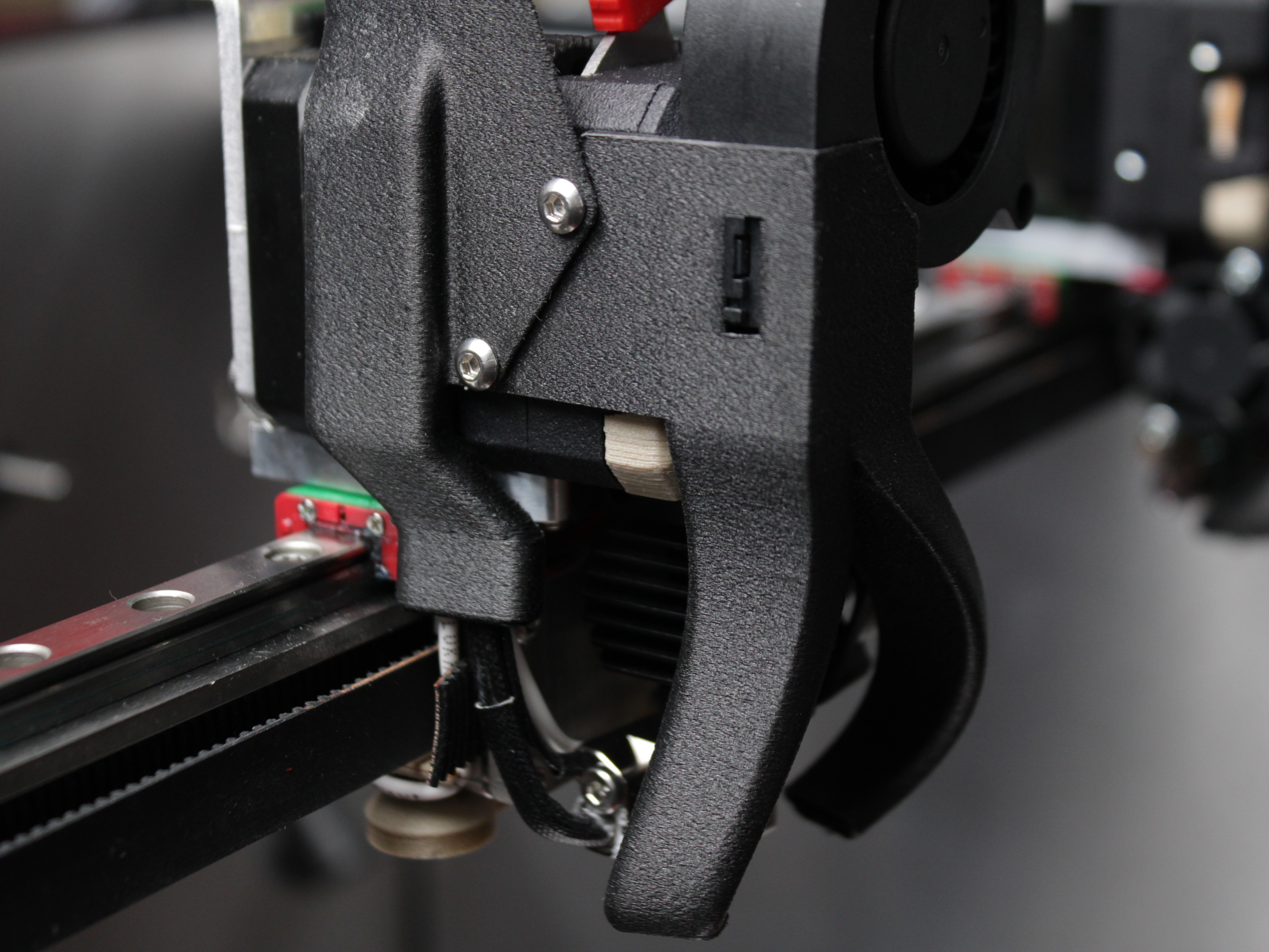
- Replace the fan shroud using the 2 mm hex screws.
- Make sure wires, including the grounding wire, are tucked properly under the wire guard without excessive bending or contact with other metal parts.
10. Final Steps & Nozzle Installation
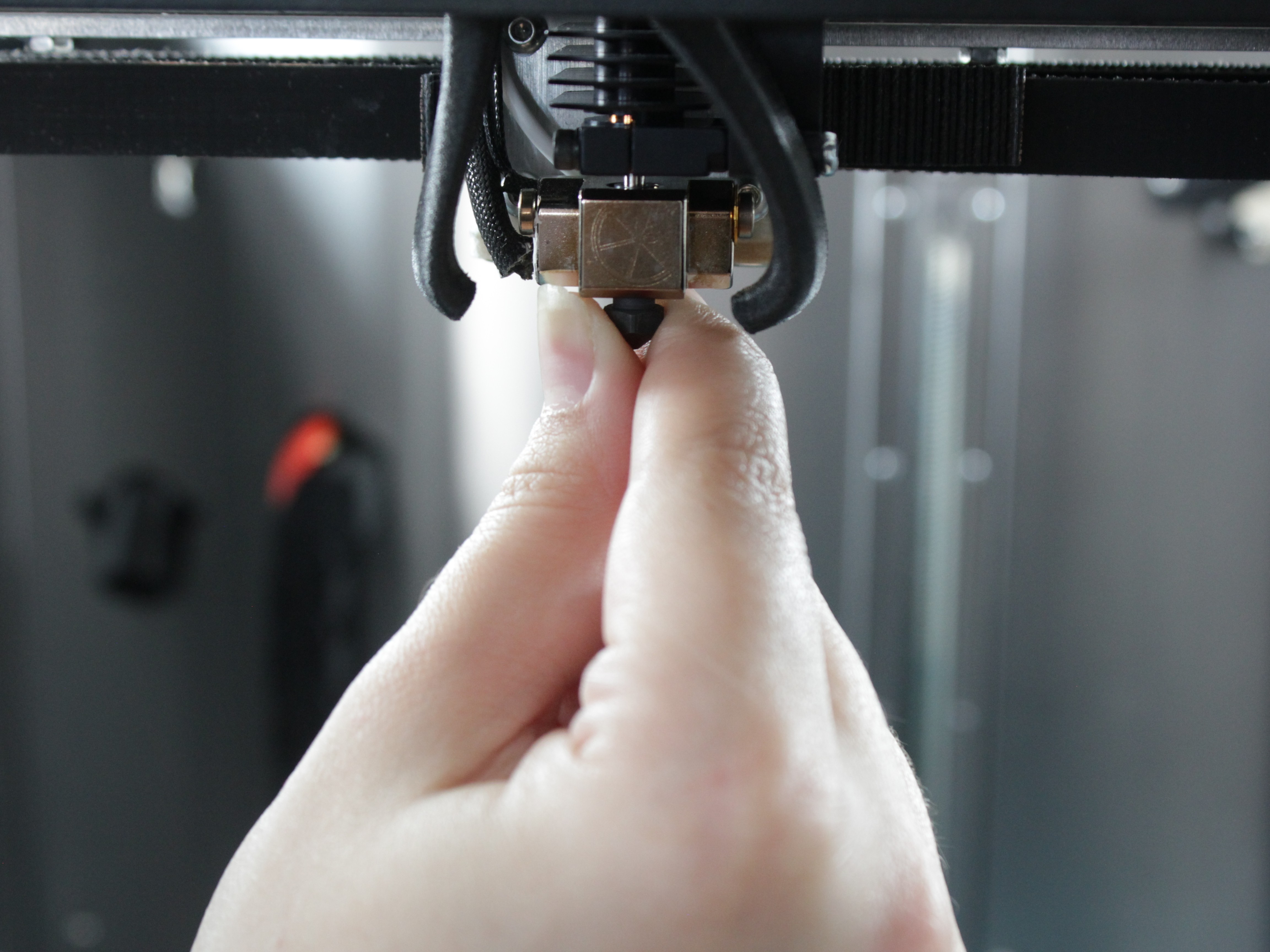
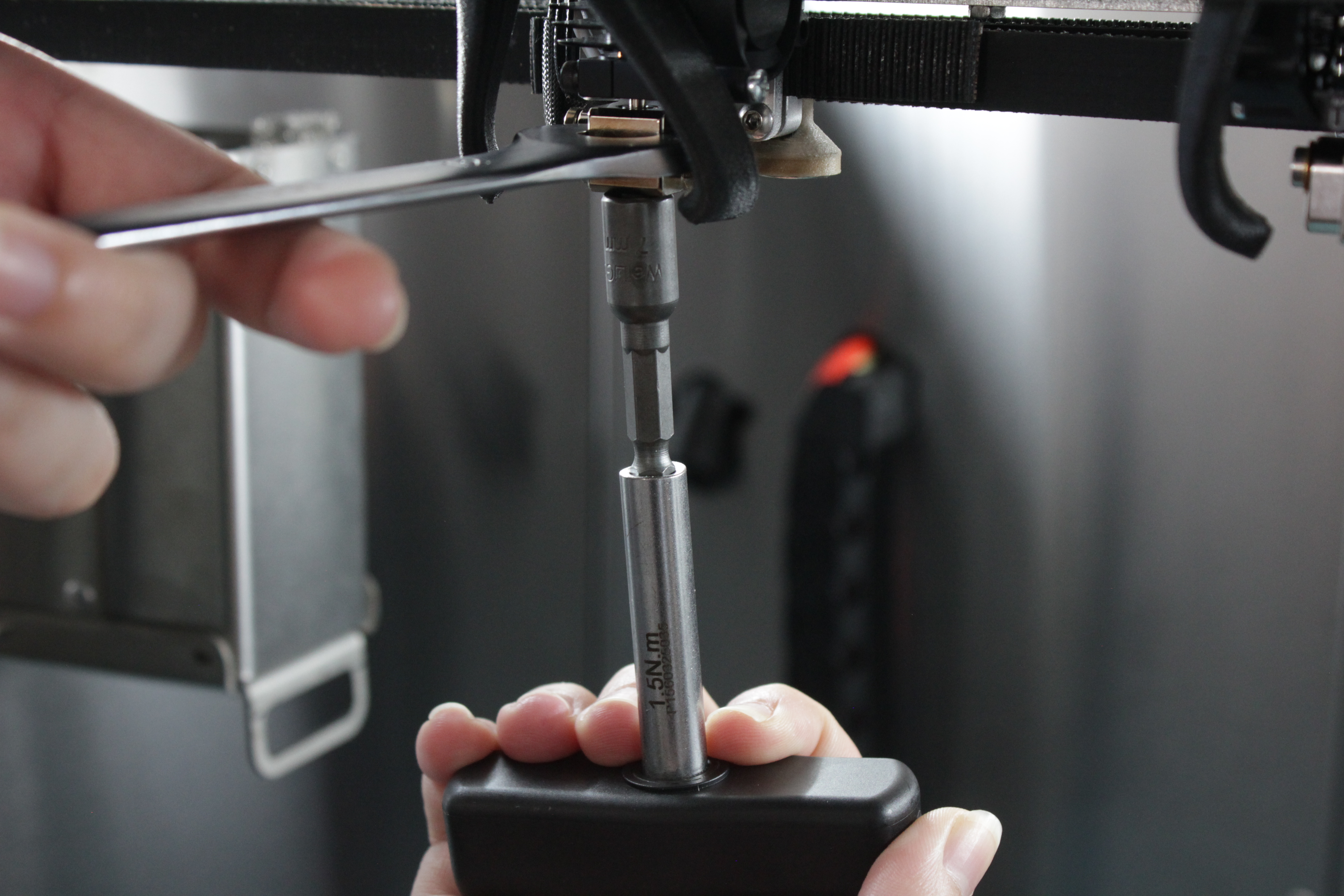
- Initial Tightening:
- Thread the nozzle in counter-clockwise (looking up from the nozzle tip) by hand or at ~1 Nm torque.
- Hold the heat block with a wrench to avoid twisting the heat break.
- Heat Soak:
- Heat the hotend to your normal printing temperature.
- Let it sit for a few minutes to ensure all components expand and seat properly.
- Final Tightening:
- Once hot, use your wrench again to slightly re-tighten the nozzle (still around 1–1.5 Nm max).
- This helps prevent leaks around the threads.
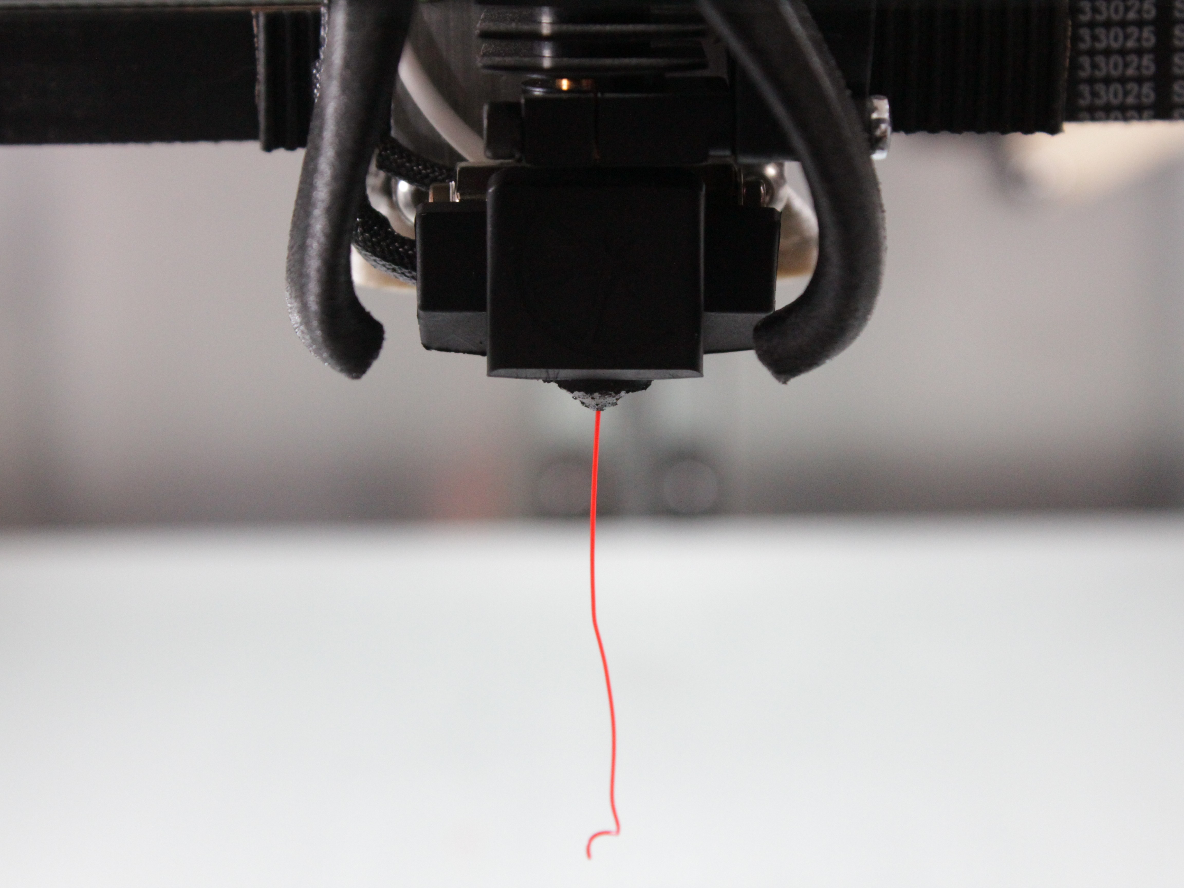
- Perform a Test Extrusion:
- Load filament to confirm a clear path and ensure no jams or leaks at the nozzle.
Detailed nozzle change procedure
For a detailed walkthrough of nozzle changes, see Nozzle Change.
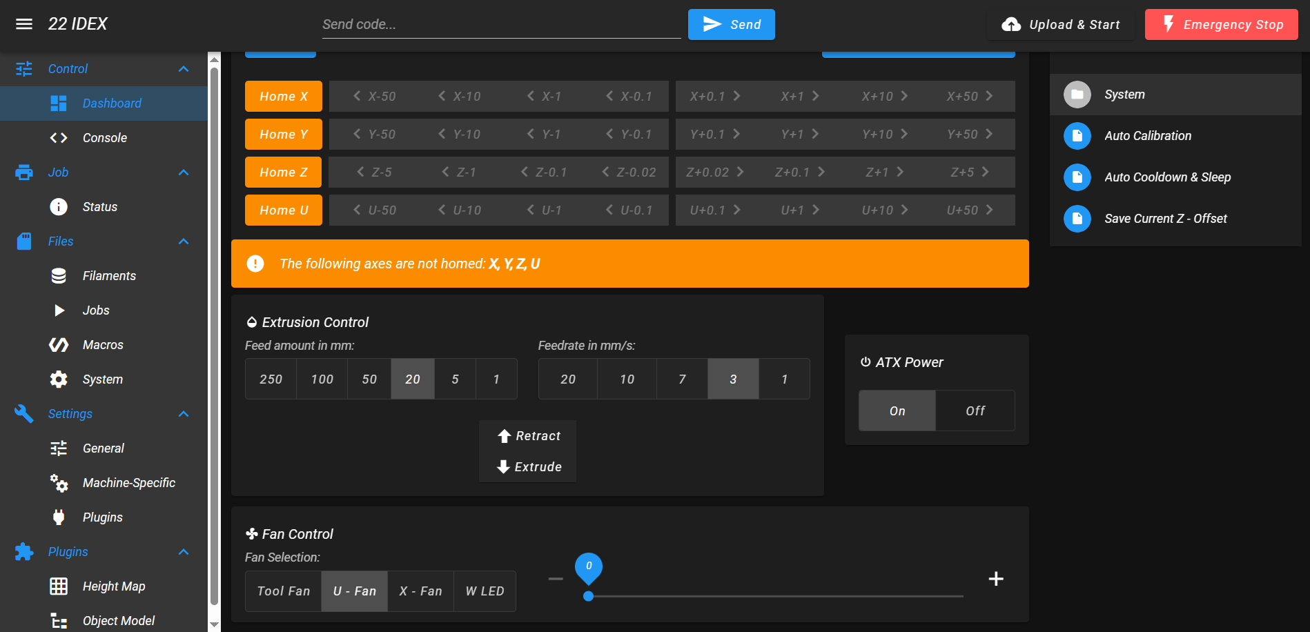
- Perform a Calibration:
- In the Web Interface, open the
Macrostab and runAuto Calibration. - Follow the on-screen instructions. This runs the full calibration sequence, including Tool Height and Z-Offset, which you need after hotend work. See the Auto Calibration guide for the full procedure.
If you encounter issues after reassembly:
- Under-extrusion or poor layer adhesion – see Poor Layer Adhesion or Under-Extrusion
- Incorrect temperature readings – see Incorrect Temperature Readings
- Heater not working – see Heater Not Working
- Ground faults – see Electrical Ground Issues
Troubleshooting
If you encounter issues during or after the procedure, work through these common problems:
FAQ
Support
If you could not find an answer here, reach out to our support team.