Motor Diagnostics
Motor with no movement, sound or holding torque — isolate a failed stepper driver, cable or motor with port and cable swaps, plus extruder motor checks.
This guide covers diagnosing motor problems on the Vision Miner 22IDEX V4. The printer has nine stepper motors – three on the Z-axis, two on the Y-axis, two tool motors (X/U-axis), and two extruder motors. Use this article when a motor stops responding, makes abnormal noise, or correlates with motion or extrusion defects.
Split the work into two paths:
- Motor not responding at all – follow Section 1 (electrical) to see whether the driver, cable, or motor failed.
- Motor runs but behaves badly (noise, vibration, heat) – see Failing Motor Diagnostics.
Before you begin - safety and risk
Read the Safety - Before You Begin article to understand the hazards involved in working on the Vision Miner 22IDEX V4 – including electrical, thermal, mechanical, and chemical risks. All procedures in this wiki are provided as recommendations only. By choosing to follow any procedure, you do so at your own risk.
Motor Overview
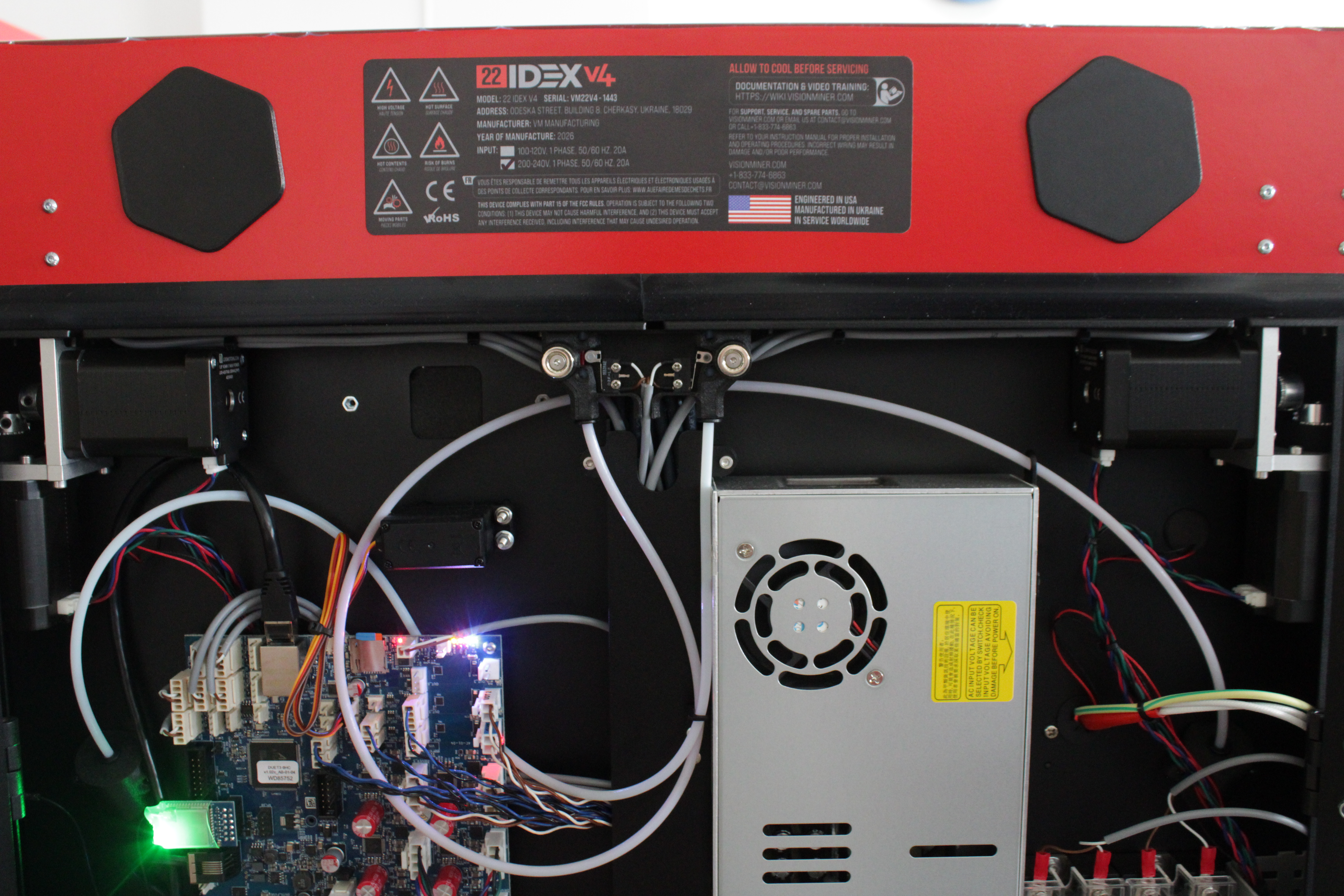
Each motor is driven by a TMC2160a on the mainboard (Duet 3 MB 6HC – six drivers) or the expansion board (three drivers).
| Motor | Qty | Location | Function |
|---|---|---|---|
| Y-axis motors | 2 | Rear electronics bay – left (T0 side) and right (T1 side), horizontal | Move the gantry in Y |
| Tool 0 motor (X) | 1 | Rear bay, left, vertical | Move Tool 0 along the X rail |
| Tool 1 motor (U) | 1 | Rear bay, right, vertical | Move Tool 1 along the X rail |
| Z-axis motors | 3 | Under the bed – T0 side, T1 side, rear center | Raise and lower the bed |
| Extruder motors | 2 | On each toolhead | Drive filament into the hotend |
1. Complete Motor Failure – Electrical Diagnostics
When a motor gives no movement, sound, or holding torque, the fault is in one of:
- Stepper driver (mainboard or expansion)
- Motor cable
- Motor
The swap sequence below substitutes one part at a time.
Drivers are soldered - replace the board if a driver dies
TMC2160a drivers are soldered to the mainboard and expansion board. A dead driver means replacing that whole board, not swapping a chip.
Never hot-swap motor cables
Always power off and unplug before connecting or disconnecting motor cables. Hot-swapping destroys the driver; damage is not recoverable.
Testing the Driver
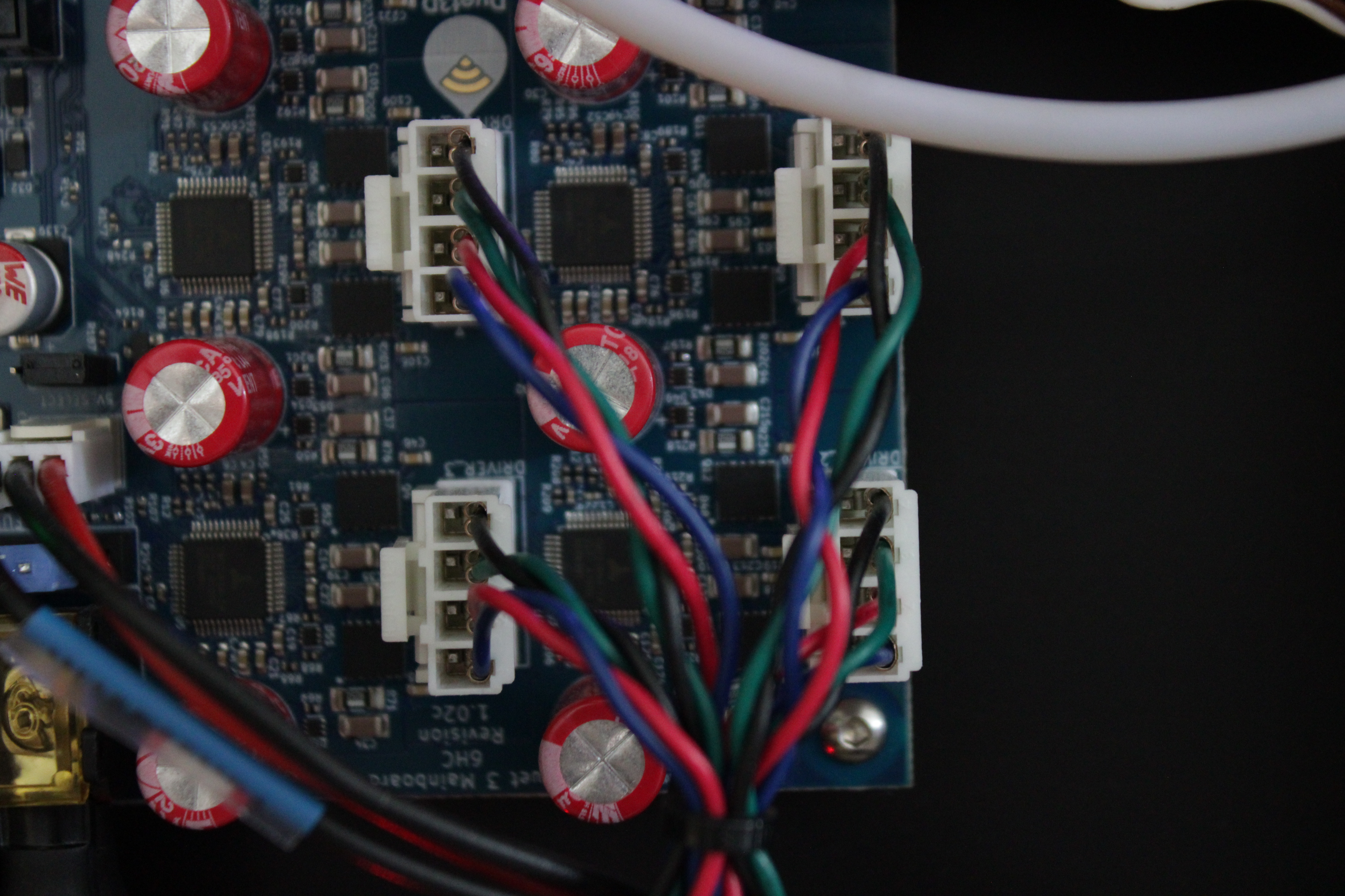
The diagram below shows how the XY and tool motors connect to the mainboard driver ports. The four drivers sit in a 2×2 block: the top row (a, b) drives the two Y-axis motors and the bottom row (c, d) drives the two tool motors (X = Tool 0, U = Tool 1).
- Identify the dead motor and note which driver port its cable uses on the Main Board or expansion board.
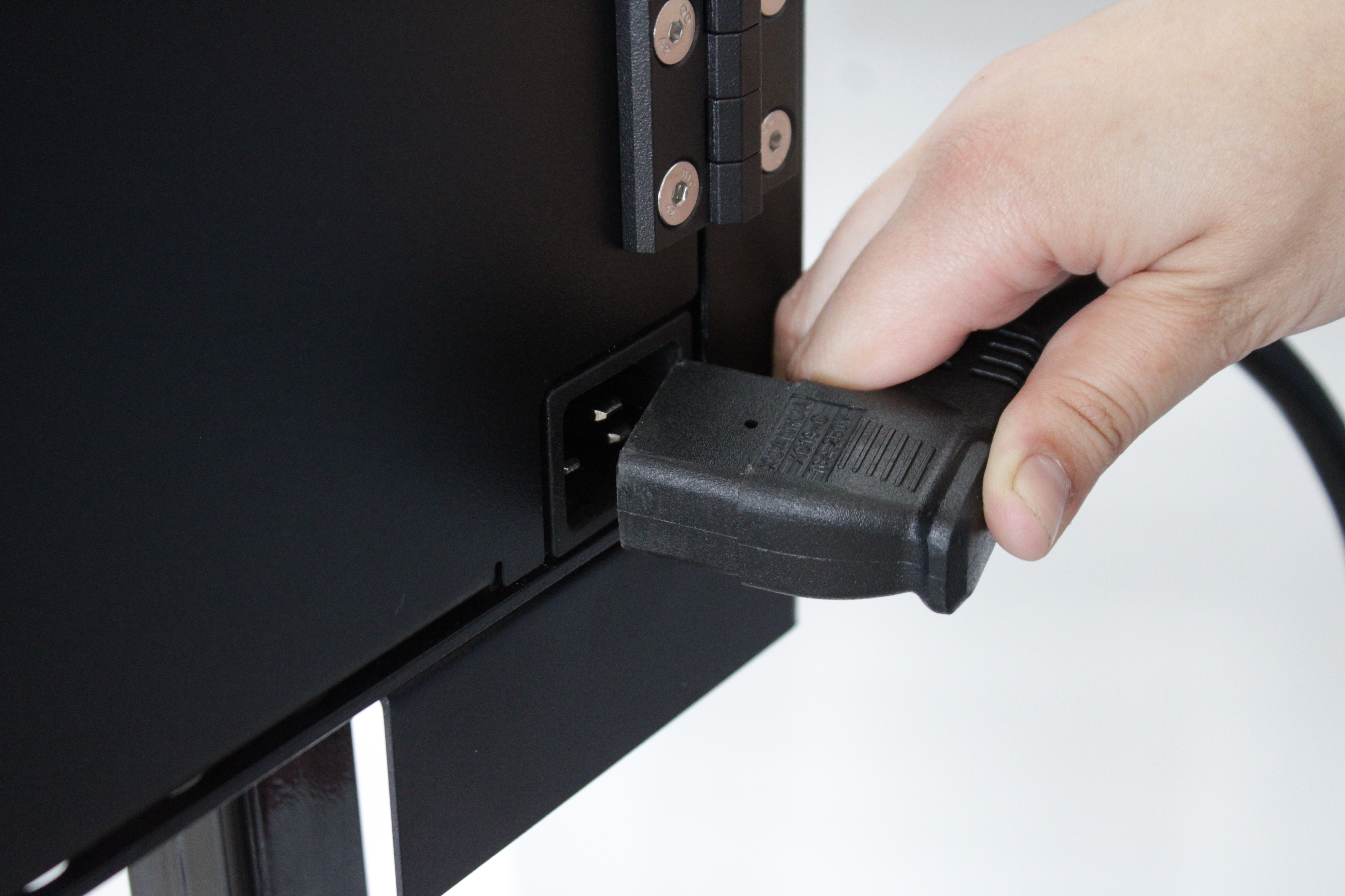
- Power off and unplug. Wait at least 60 seconds for capacitors to discharge.
Use the reference diagram below to see exactly where each motor is and which driver port it connects to, so you know which cable belongs to which motor before re-routing anything.
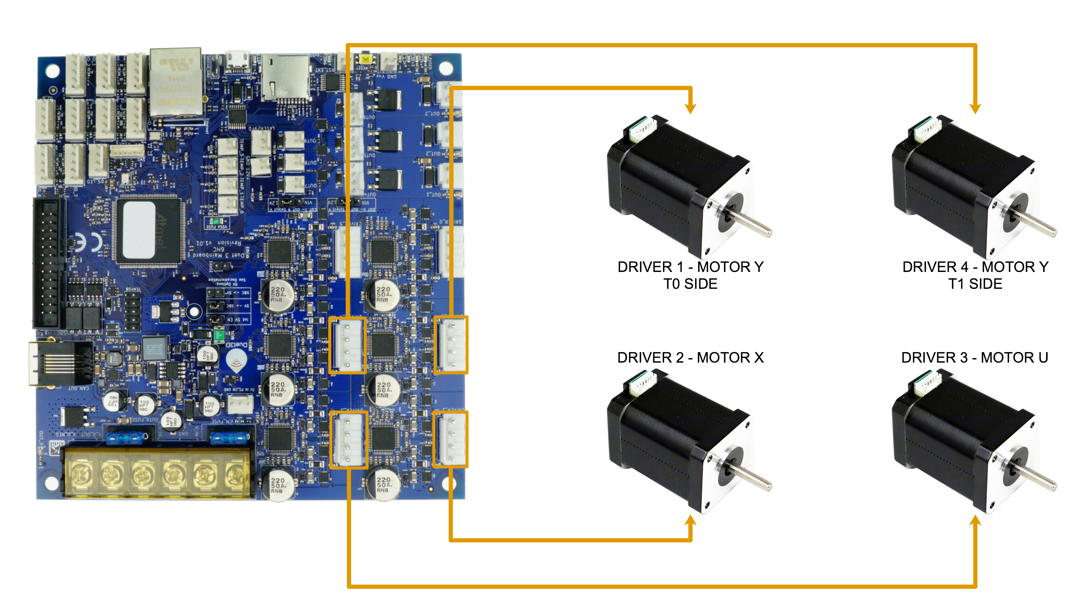
- If a Y-axis motor is dead, swap each Y connector with the tool-driver port directly below it: move cable A → C and C → A, and B → D and D → B.
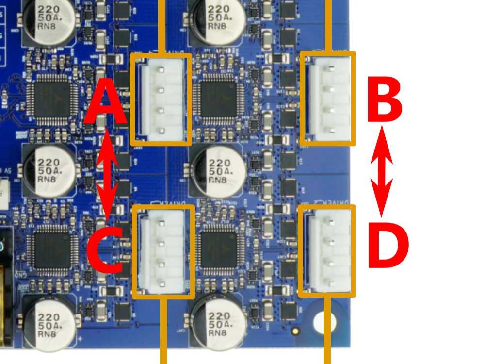
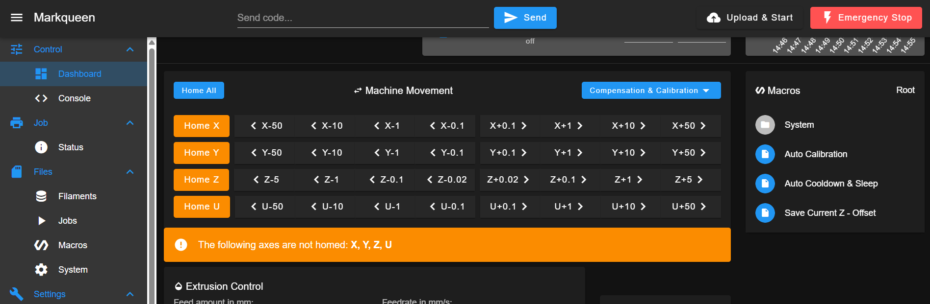
Power on, enable the Movement Without Homing macro (Macros → System → Movement Without Homing), and slowly move both axes, X and U, while listening – these now drive the Y motors through the tool drivers. Send M18 in the Console after each move to release the motors. If the motor now runs, the original driver is bad; if it still does nothing, the driver is fine – continue to Testing the Cable.
- If a tool motor (X or U) is dead, swap the two tool connectors with each other: move cable C → D and D → C.
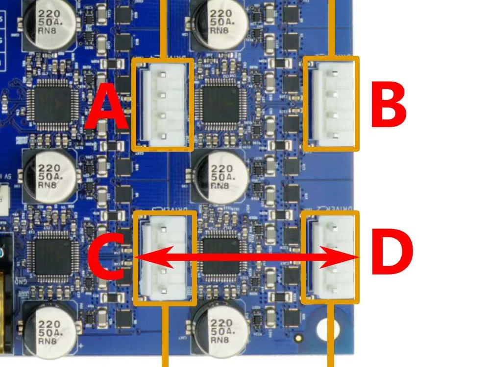
Power on, enable the Movement Without Homing macro (Macros → System → Movement Without Homing), and move both axes, X and U. If the fault follows to the other axis (for example, U failed before and now X fails), the motor or cable is bad; if the same axis still fails, the driver is bad.
Testing the Cable
If the suspect motor behaves exactly the same after the driver test (still dead, noisy, or grinding), test its cable. On each side of the machine the motors sit in pairs – one Y-axis motor and one tool motor – that share the same cable type (T0 side or T1 side). Swapping the two cables within a pair shows whether the cable is at fault.
Never power a driver with nothing connected
Always have a motor plugged into a driver before powering on or commanding movement. An unloaded driver will burn out.
No limits without homing
Movement Without Homing ignores the endstops. Leave clearance for the toolhead and the crossbar, and stop before any axis reaches its physical limit – otherwise you can damage the machine.
-
Power off and unplug. Wait at least 60 seconds, and return any cables you moved during the driver test to their original ports.
-
Swap the two cables of the pair on the affected side – exchange the Y-motor cable and the tool-motor cable in that corner.
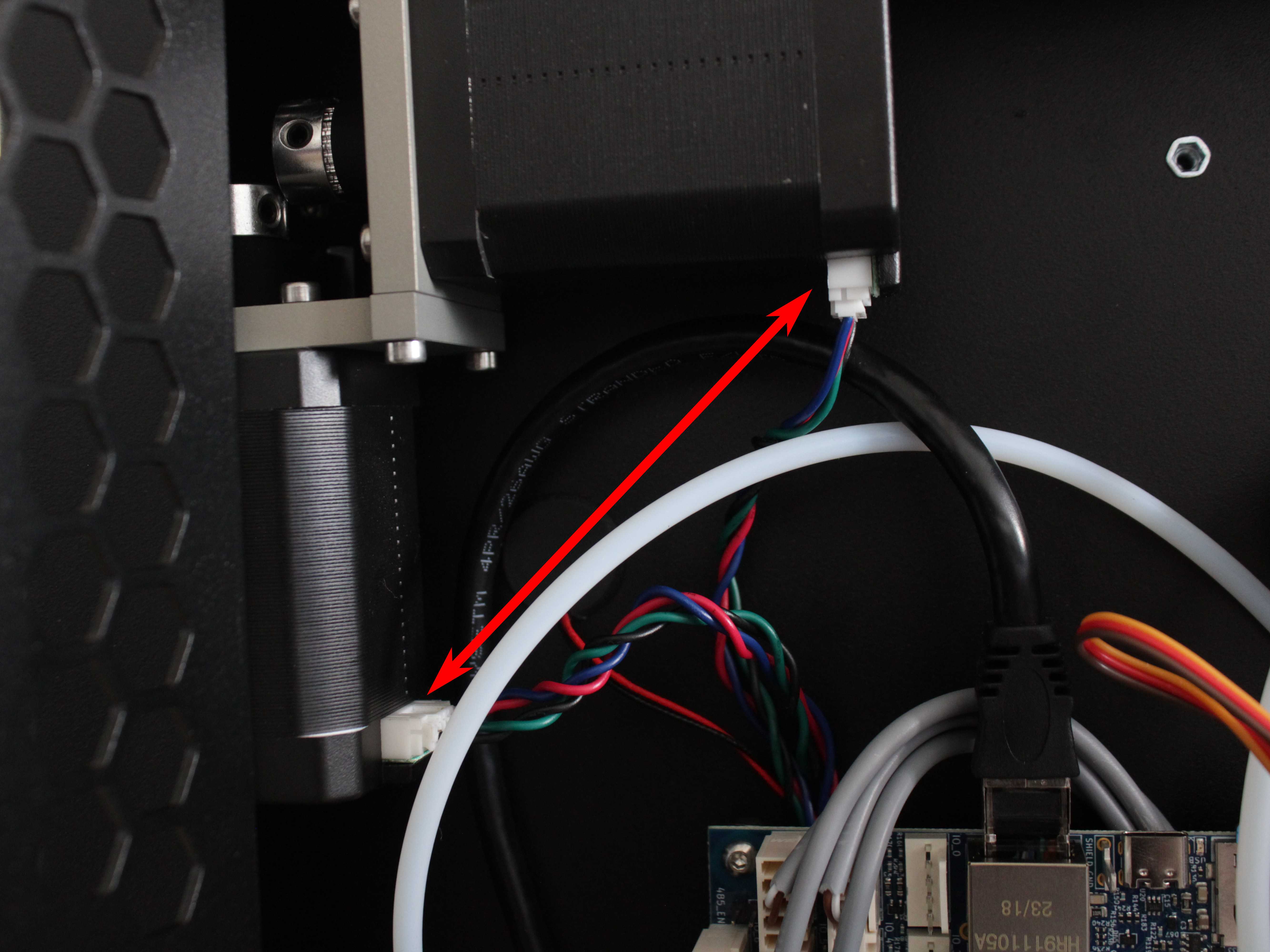
- Power on, enable the Movement Without Homing macro (Macros → System → Movement Without Homing), and move the other axis of the pair – when testing a Y motor, move the tool axis (X/U); when testing a tool motor, move Y.
- If the motor now runs correctly (no noise) – the original cable is the fault. Replace it:
| Cable Part | Motor Type | Shopify Link |
|---|---|---|
| XY-Motor Wire - T0 Side | Y-axis (left) or Tool 0 (X-axis) | Order |
| XY-Motor Wire - T1 Side | Y-axis (right) or Tool 1 (U-axis) | Order |
| ToolHead Wiring Harness - T0 & T1 | Extruder motors | Order |
- If it still does not run – driver and cable are good; the motor is defective.
Z-axis motors are not covered by this test
This pair-swap cable test applies to the X, Y, and tool motors only. If a Z motor grinds and the bed is stuck at the bottom of its travel, see Z-Motor Alignment. For any other Z motor or cable fault, contact our support team.
Not sure which side is bad?
If you do not know which side's motor is faulty, swap both pairs and test each in turn.
Motor Replacement
- If the motor is confirmed bad:
| Motor Type | Replacement Part | Notes |
|---|---|---|
| Y-axis and tool (X/U) motors | XY-Motor | Full steps in XY motor replacement |
| Z-axis motors | Z-Lead Screw Motor | This wiki does not yet publish a dedicated Z motor walkthrough; contact support for the procedure |
| Extruder motors | Extruder Assembly | Replace the complete extruder assembly |
2. Extruder Motor Issues
Before blaming the extruder motor, rule out the extruder itself – a clog or debris in the drive gears can stall a perfectly good motor. The driver- and cable-swap tests in Section 1 do not apply to the extruder motors.
Symptoms
- Rhythmic clicking or knocking while printing
- Filament with grind marks
- Under-extrusion or uneven extrusion width
- Skipping under load
- Hot motor housing
Diagnosis
-
Unload the filament from the affected tool.
-
Allow cold extrusion so the extruder can turn without heating the nozzle – in the Console, send
M302 P1– then command a short extrusion and watch the drive gear. -
Try to stop the drive gear with your fingers as it turns:
- If you can stop it, the motor is too weak – this is a motor/electronics fault. Contact our support team; the extruder cannot be checked with the Section 1 swap method.
- If it turns and you cannot stop it, the motor is fine – continue.
-
Inspect the drive gears for dust, dirt, or debris. If you find contamination, clean it off – that was likely the cause.

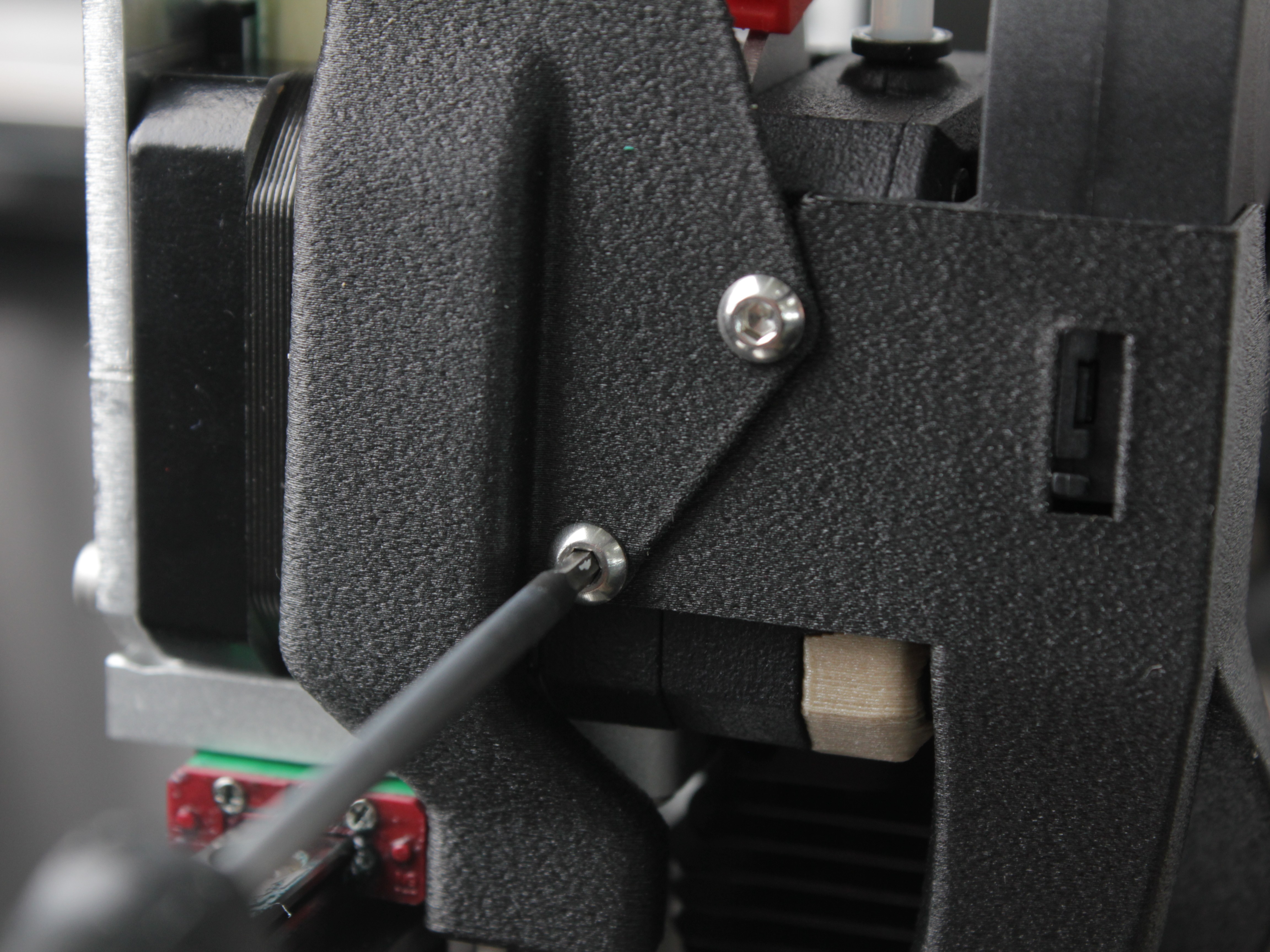
- If the gears look clean, disassemble the extruder to inspect inside. Remove the fan shroud screws and take off the fan shroud.
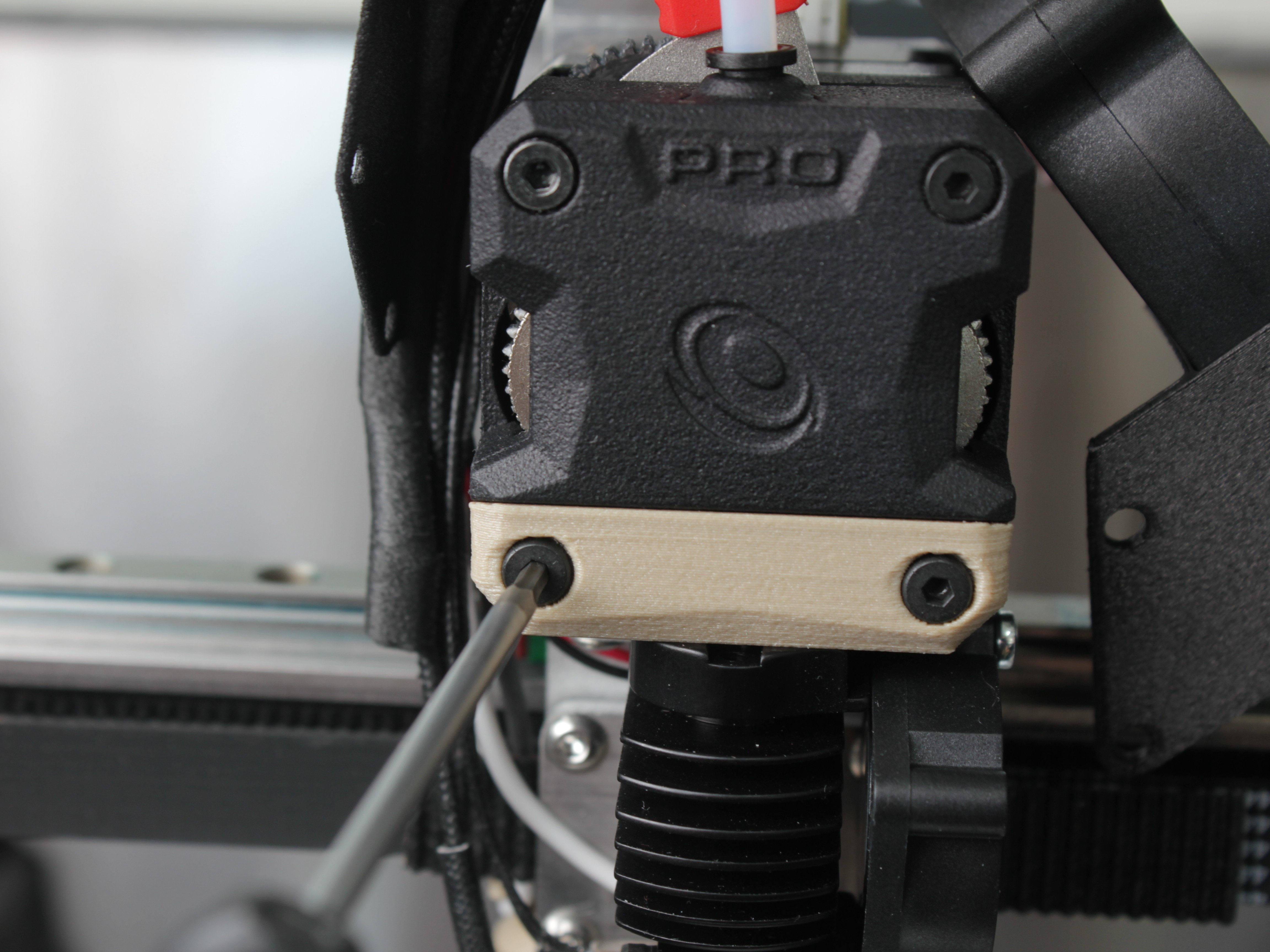
- Unscrew the four screws on the front extruder panel.
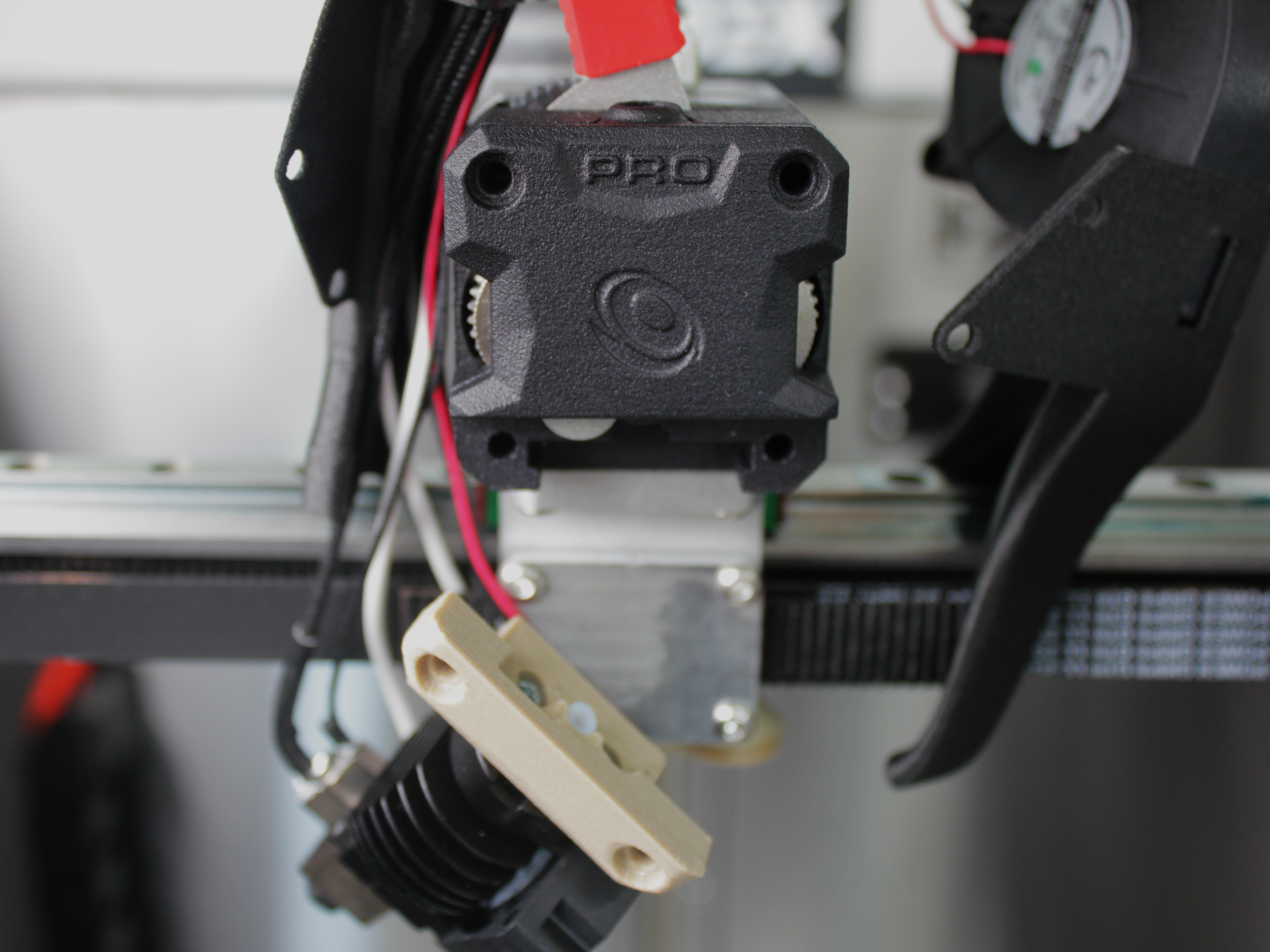
- Remove the hotend by pulling it toward you, then take off the front cover.
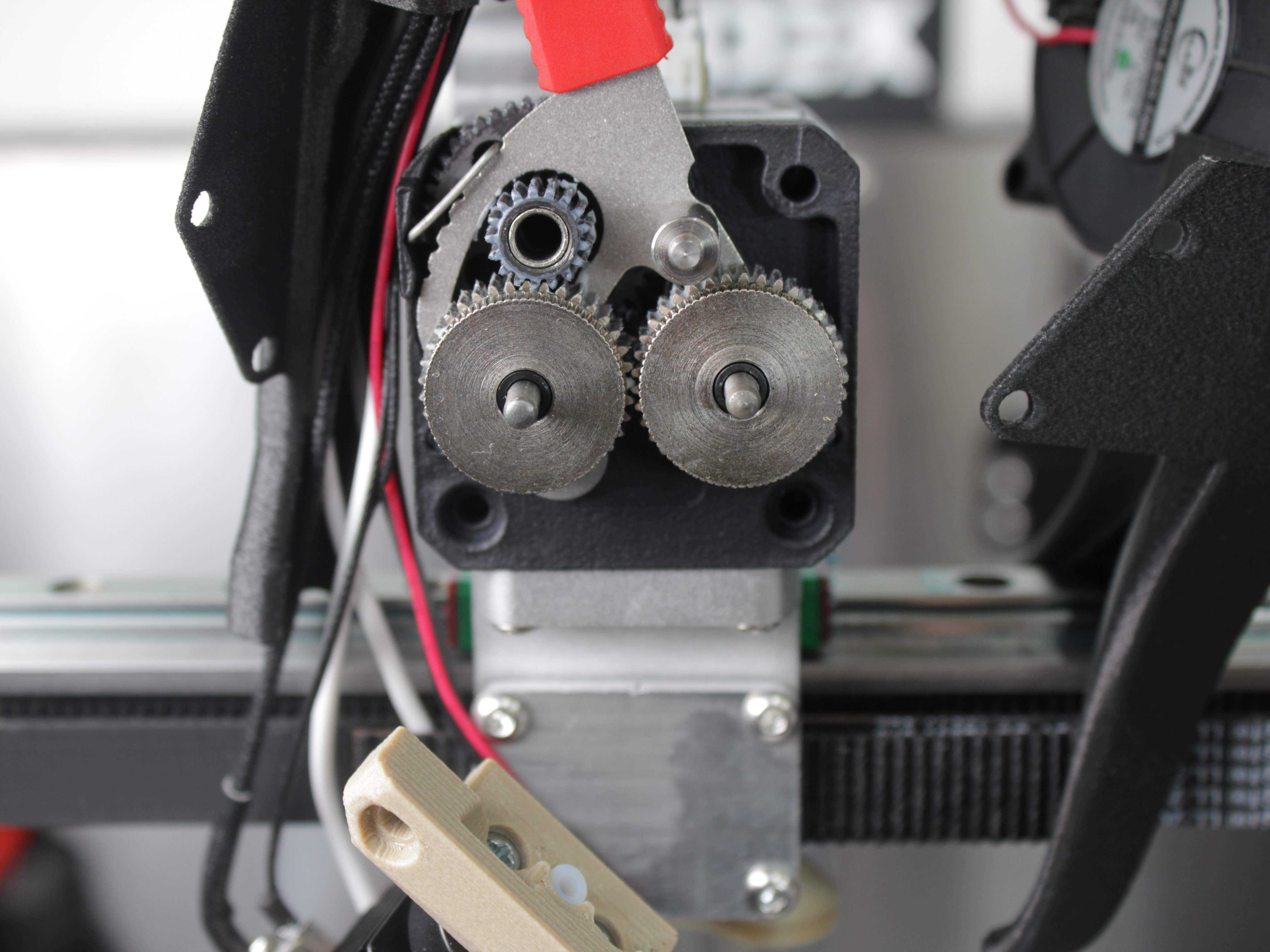
- Inspect the drive gears for wear, damage, or defects.
-
If the gears or extruder are worn or damaged, contact our support team and order a new Extruder Assembly. If everything looks fine but the filament still will not feed, the clog is inside the hotend – see Unclogging.
-
Reassemble the extruder in reverse order.
FAQ
Troubleshooting
Support
If you could not find an answer here, reach out to our support team.